
Is It Possible For Teens to Cheat An At Home Drug Test? - cvs synthetic urine
The intended output of many lasers in laser scanning is Gaussian. At distance $z$ from the waist, the radius of a Gaussian beam is calculated as $$w(z) = w_0 \sqrt{1+(z/z_R)^2},$$ where $w_0$ is the waist radius, and $z_R = \pi w_0^2/\lambda$ is the Rayleigh range, depending on the waist $w_0$ and the wavelength $\lambda$. When distance $z$ is considerably larger than $z_R$, the radius $w$ grows approximately linearly, $$w(z) \approx \theta z,$$ where $$\theta = \frac{\lambda}{\pi w_0}$$ is the divergence angle.
Beam waistof Laser formula
To avoid this, the aperture should be large enough that the bean intensity at the edge is at most $1$ % of the central intensity. That works out to be a aperture $1.5$ times larger than the beam diameter.
Gaussianbeam waistcalculator
Jul 4, 2024 — A polarizing filter can separate polarized light moving at a particular angle from non-polarized light. To find the optimum position to filter ...
A Gaussian beam does not have a sharp edge. It is brightest at the center and fades away as you get farther from the beam axis. So the intensity isn't $0$ outside the beam radius.
Gaussianbeam waistformula
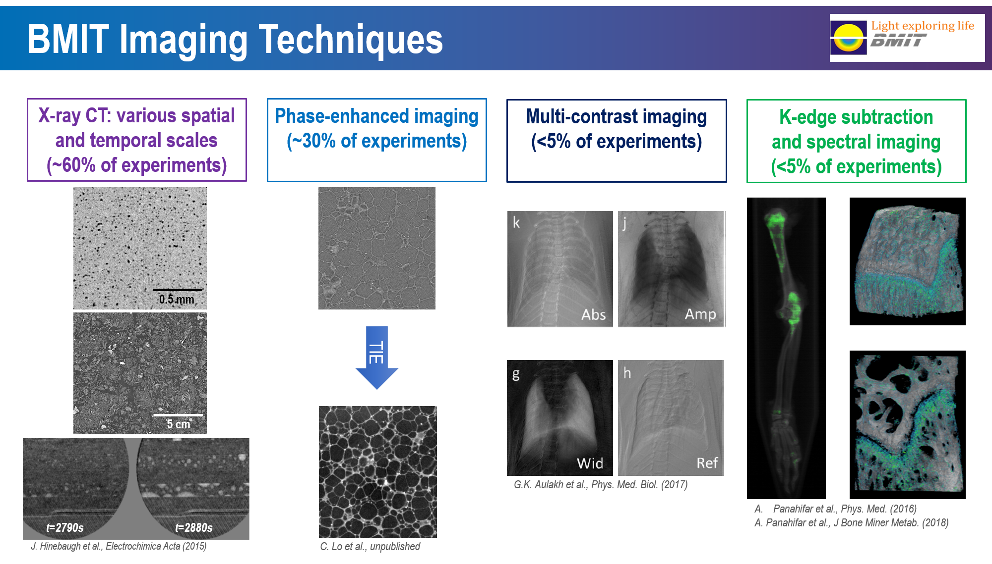
Multiple image radiography (MIR) is an extension of DEI to three or more images. Typically images are collected at 3 – 11 positions and then processed to yield three images depicting separately the effects of refraction, ultra-small angle scatter and attenuation by the object. All three images have good contrast, in part because they are virtually immune from degradation due to scatter.
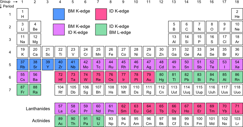
K-Edge Subtraction (KES) utilizes the discontinuity in the X-ray absorption across the absorption edge of the selected contrast element and creates a logarithmic subtraction image from two images acquired just above and below the K-edge energy of the contrast element. From the logarithmic subtraction of the two images, the visibility of structures, the visibility of structures containing the contrast element can be greatly enhanced and the signals to the other structures are practically suppressed. Spectral KES is similar to conventional KES imaging. The spectral method, termed 'spectral-KES' employs a continuous spectrum encompassing an absorption edge of an element within the object. The spectrum is prepared by a bent Laue monochromator with appropriate focal and energy dispersive properties. The monochromator focuses the spectral beam at the object location, which then diverges onto an area detector such that one dimension in the detector is an energy axis. A least-squares method is used to interpret the transmitted spectral data with fits to either measured and/or calculated absorption of the contrast and matrix material-water. The spectral-KES system is very simple to implement and is comprised of a bent Laue monochromator, a stage for sample manipulation for projection and computed tomography imaging, and a pixelated area detector.
X-ray absorption contrast imaging is the most common imaging technique, and is the technique used in industrial or hospital X-ray imaging, also called radiography. The contrast is driven by a combination of three factors: 1) Absorption differences; 2) Density differences; 3) Object thickness. Synchrotron based X-ray absorption contrast imaging uses a small spot size, high brightness, and a monochromatic beam to scan samples and can provide a high resolution composite image. Using a monochromatic source avoids the beam-hardening issues commonly found in conventional sources. High brightness can result in faster imaging for a comparable resolution.
You need a bigger aperture than the beam diameter to avoid cutting off the outer portion of the beam. If you do that, you have passed the beam through a large pinhole. A pinhole causes diffraction. It isn't as bad with a large pinhole, but it is enough that the beam has a larger divergence angle than it should.
tibiotibio, -a adjetivo 1 (desagradablemente templado) lukewarm; (agradablemente templado) warm 2 (poca entusiasta) (acogida) lukewarmEXPRESIONES → poner ...
Beam waistcalculator
Near the beam waist, rays follow hyperbolic paths. Far from the beam waist, the hyperbolic beam approximates a cone. The divergence angle is the angle of the vertex of the cone. See the RP Photonics Encyclopedia article Gaussian Beams for more. It has a beam calculator.
X-ray phase-contrast imaging techniques make use of the refraction of X-rays by the sample in image formation. This provides considerable additional information in the image compared to imaging methods relying solely on X-ray absorption by the sample. Phase-contrast imaging highlights edges and internal boundaries of a sample and is thus complementary to absorption contrast, which is more sensitive to the bulk of the sample. Phase-contrast can also be used to image low-density materials, which do not absorb X-rays sufficiently to form a distinct absorption X-ray image. The following phase contrast imaging techniques are available at the BMIT.
This periodic table show the absorbtion edges that can be reached at the beamlines. In this table BM indicates the bend magnet source (05B1-1) and ID indicates the insertion device (O5ID-2).
Lite path. 36 likes · 4 talking about this. I have created Lite Path with the intention to provide a place for spiritual growth, healing and to.
Gaussianbeam waist
Analyser-based imaging is based on placing an analyser crystal between the sample and the detector. The crystal acts as an angular filter and only allows a small range of refracted and scattered X-rays to reach the detector. This allows for the measurement of an absorption image that is not blurred by scattered X-rays. By tuning the analyser crystals refracted X-rays result in increased or decreased intensity in the image. Images are taken at two angles and then processed to obtain separate absorption and refraction images. Diffraction-enhanced imaging (DEI) is an analyzer crystal based X-ray imaging technique that has very high sensitivity to small changes in the refractive index. This makes it suitable for soft tissues such as in mammography or bone cartilage studies.
This makes it hard to describe the beam diameter. The way it is done is to pick the diameter where the intensity has dropped by a factor is $1/e^2$.
Stack Exchange network consists of 183 Q&A communities including Stack Overflow, the largest, most trusted online community for developers to learn, share their knowledge, and build their careers.
I am modeling a laser beam from a laser scanning device as a Gaussian beam. I am not sure how to decide the waist radius $w_0$. For example, it is given that laser beam footprint at exit is $5$ mm and the divergence is reported to be 0.5 mrad. Wavelength is 1500 nm.
These lenses are thicker at the edge than in the centre and flat on one side. The plano-concave lenses are used to expand light beams or to increase focal ...
Beam waistof laser
Eye exam with 3D scan. $99 at participating locations. View offer ; Quality eyewear. hundreds of styles available. View glasses ; Local businesses. 130 stores ( ...
Computed tomography (CT) makes use of computer-processed combinations of many X-ray projections taken from different angles of a sample to produce cross-sectional (tomographic) images of specific areas of the sample, which provides three-dimensional (3D) structural information of the scanned sample. CT is available at BMIT and can combine with any imaging techniques at BMIT, such as absorption-CT, phase-contrast-CT, DEI-CT, Spectral KES-CT.
But then the radius is equal to the output radius $5mm/2 = 2.5 mm$ at distance $z \approx 4.6209 m$, which is insane. The device is surely not 5 meters long. So have I understood the parameters of Gaussian beam incorrectly, or is there some optical tricks happening inside the laser device? Or is it so that the Gaussian model is accurate only for the Gaussian shape, not for the radius calculation?
Gaussianbeamcalculator
In-line phase-contrast imaging, which is also called phase-contrast radiography, is the most common technique and the easiest method to use. The synchrotron provides the spatially coherent source needed for this method. The setup is very similar to a typical radiograph with a source, a sample and a detector. The difference is that rather than placing the detector close to the sample it is located at some distance which gives rise to Fresnel fringes. This method is most sensitive to abrupt changes in the refractive index. This leads to an edge enhancement which increases the contrast of the edges of structures or material boundaries.
Then we may calculate $$w_0 = \frac{\lambda}{ \pi \theta} = \frac{1500 nm}{\pi \times 0.5 \times 10^{-3}} = 0.0009549... m$$ and $$z_R = \pi w_0^2/\lambda = \frac{\pi \times (0.0009549... m)^2}{1500 nm}= 1.909... m.$$
Ball lenses have very low spherical aberration and so focus and collimate light very accurately; a sapphire ball has only 23% of the aberration of an ...
It is usually assumed that the waist of the laser beam is at the exit pupil. However, that may not be true in your case. The way you phrase it (which I assume is how the laser specs are stated) does not necessary imply that the 5 mm at the exit means that the waist diameter is 5 mm. It could be that the device contains some lenses producing a converging beam at the exit. That would make sense in the context of laser scanning.
If the aperture is $5$ mm, the beam diameter is at most $3.33$ mm, and the beam radius $1.66$ mm. A beam with this radius would have a smaller divergence angle than advertised.
What you can do is to make some measurements to get a rough estimate of the beam size at different distances. A plot of these beam sizes as a function of distance should give you an idea of the location of the waist.
very large fresnel lenses I am interested in your capacity to design and manufacture a very large diameter 1 5 - 2m diameter fresnel lenses If you are able ...
Or the beam could be something other than a perfect Gaussian beam. The presence of higher modes would make a beam with a $1.66$ mm radius have a larger than ideal divergence angle.
Beam waistformula
27 mm to inches as a decimal · 27 mm ≈ 1.063 inches · 27 mm to inches as a fraction · 27 mm ≈ 1 8/127 inches · 28 mm to inches
2024 Product Catalog. Boston Scientific now offers an online solution to search and learn about Endoscopy products. Boston Scientific's new eCatalog is ...
Apr 5, 2023 — Anker Powerline+ USB C to USB 3.0 Cable ... d better be familiar with each of its types and versions. ... Usually, you can tell a USB 2.0, USB 3.0, ...


 Ms.Cici
 8618319014500