
Iris - MMKB, the Mega Man Knowledge Base - zero iris
Thorlabs' LIDT testing is done in compliance with ISO/DIS 11254 and ISO 21254 specifications.First, a low-power/energy beam is directed to the optic under test. The optic is exposed in 10 locations to this laser beam for 30 seconds (CW) or for a number of pulses (pulse repetition frequency specified). After exposure, the optic is examined by a microscope (~100X magnification) for any visible damage. The number of locations that are damaged at a particular power/energy level is recorded. Next, the power/energy is either increased or decreased and the optic is exposed at 10 new locations. This process is repeated until damage is observed. The damage threshold is then assigned to be the highest power/energy that the optic can withstand without causing damage. A histogram such as that below represents the testing of one BB1-E02 mirror.
Pulsed Nanosecond Laser Example: Scaling for Different Pulse DurationsSuppose that a pulsed Nd:YAG laser system is frequency tripled to produce a 10 Hz output, consisting of 2 ns output pulses at 355 nm, each with 1 J of energy, in a Gaussian beam with a 1.9 cm beam diameter (1/e2). The average energy density of each pulse is found by dividing the pulse energy by the beam area:
Join us for an exclusive keynote by Leslie Kimerling, Co-Founder & CEO of Double Helix Optics, at our Innovation Summit in Cupertino, CA on December 12! 🧬 Leslie will explore groundbreaking trends in life sciences and dive into the world of super-resolution 3D microscopy—powered by Nobel Prize-winning technology. Discover how Double Helix Optics is revolutionizing imaging with stunning 3D molecular visualizations. 🌟 Don't miss your chance to learn from top experts in optics and life sciences at this free in-person event! 📅 December 12, 2024 | 8:45 AM PT 📍 Quinlan Community Center, Cupertino, CA 💡 Register now: https://ow.ly/gjsL50UbcvO #EdmundInnovationSummit #EdmundOptics #EdmundEvents
Now compare the maximum energy density to that which is specified as the LIDT for the optic. If the optic was tested at a wavelength other than your operating wavelength, the damage threshold must be scaled appropriately [3]. A good rule of thumb is that the damage threshold has an inverse square root relationship with wavelength such that as you move to shorter wavelengths, the damage threshold decreases (i.e., a LIDT of 1 J/cm2 at 1064 nm scales to 0.7 J/cm2 at 532 nm):
This scaling gives adjusted LIDT values of 0.08 J/cm2 for the reflective filter and 14 J/cm2 for the absorptive filter. In this case, the absorptive filter is the best choice in order to avoid optical damage.
Silicone contactlens
We are proud to sponsor PhotonicsSweden's Award (2nd prize) for an outstanding master thesis in the field of photonics/optics. A big congratulations to Adrian Vågberg for receiving this well-deserved recognition! 🎉 His thesis, "CO2 Absorption Spectroscopy with Backward Wave OPOs," showcases the innovative research that drives our industry forward. We’re thrilled to support the next generation of bright minds in advancing photonics.
This adjustment factor results in LIDT values of 0.45 J/cm2 for the BB1-E01 broadband mirror and 1.6 J/cm2 for the Nd:YAG laser line mirror, which are to be compared with the 0.7 J/cm2 maximum energy density of the beam. While the broadband mirror would likely be damaged by the laser, the more specialized laser line mirror is appropriate for use with this system.
In order to illustrate the process of determining whether a given laser system will damage an optic, a number of example calculations of laser induced damage threshold are given below. For assistance with performing similar calculations, we provide a spreadsheet calculator that can be downloaded by clicking the button to the right. To use the calculator, enter the specified LIDT value of the optic under consideration and the relevant parameters of your laser system in the green boxes. The spreadsheet will then calculate a linear power density for CW and pulsed systems, as well as an energy density value for pulsed systems. These values are used to calculate adjusted, scaled LIDT values for the optics based on accepted scaling laws. This calculator assumes a Gaussian beam profile, so a correction factor must be introduced for other beam shapes (uniform, etc.). The LIDT scaling laws are determined from empirical relationships; their accuracy is not guaranteed. Remember that absorption by optics or coatings can significantly reduce LIDT in some spectral regions. These LIDT values are not valid for ultrashort pulses less than one nanosecond in duration.
Germanium IRLens
Join us in-person for a FREE event of learning and networking at the Quinlan Community Center in Cupertino! 🎉 🔬 Save the Date! 🔬 Optical Solutions for Life Sciences: Maximizing Performance, Minimizing Costs ✨ Discover the cutting-edge trends and technologies powering successful optical systems in life science applications. 📅 When: December 12, 2024 | 8:45 AM PT 📍 Where: Quinlan Community Center, Cupertino, CA 🔹 Live presentations & demos from experts 🔹 Expert insights on life science trends 🔹 Networking with industry leaders 🔹 Lunch, coffee & beverages included! Let’s innovate and elevate the future of optics in life sciences! ✨ 🎟️ Register Now – Limited spots available! https://ow.ly/4NB850U4JNc #EdmundInnovationSummit #EdmundOptics #EdmundEvents
While this rule of thumb provides a general trend, it is not a quantitative analysis of LIDT vs wavelength. In CW applications, for instance, damage scales more strongly with absorption in the coating and substrate, which does not necessarily scale well with wavelength. While the above procedure provides a good rule of thumb for LIDT values, please contact Tech Support if your wavelength is different from the specified LIDT wavelength. If your power density is less than the adjusted LIDT of the optic, then the optic should work for your application.
The adjusted LIDT value of 350 W/cm x (1319 nm / 1550 nm) = 298 W/cm is significantly higher than the calculated maximum linear power density of the laser system, so it would be safe to use this doublet lens for this application.
Please note that we have a buffer built in between the specified damage thresholds online and the tests which we have done, which accommodates variation between batches. Upon request, we can provide individual test information and a testing certificate. Contact Tech Support for more information.
Optical lenses
The energy density of your beam should be calculated in terms of J/cm2. The graph to the right shows why expressing the LIDT as an energy density provides the best metric for short pulse sources. In this regime, the LIDT given as an energy density can be applied to any beam diameter; one does not need to compute an adjusted LIDT to adjust for changes in spot size. This calculation assumes a uniform beam intensity profile. You must now adjust this energy density to account for hotspots or other nonuniform intensity profiles and roughly calculate a maximum energy density. For reference a Gaussian beam typically has a maximum energy density that is twice that of the 1/e2 beam.
However, the maximum power density of a Gaussian beam is about twice the maximum power density of a uniform beam, as shown in the graph to the right. Therefore, a more accurate determination of the maximum linear power density of the system is 1 W/cm.
Extra-thick retaining rings offer several features that aid in mounting high-curvature optics such as aspheric lenses, short-focal-length plano-convex lenses, and condenser lenses. As shown in the animation to the right, the guide flange of the spanner wrench will collide with the surface of high-curvature lenses when using a standard retaining ring, potentially scratching the optic. This contact also creates a gap between the spanner wrench and retaining ring, preventing the ring from tightening correctly. Extra-thick retaining rings provide the necessary clearance for the spanner wrench to secure the lens without coming into contact with the optic surface.
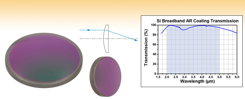
Thorlabs' Ø1/2" and Ø1" Silicon (Si) Plano-Convex Lenses are available with a broadband AR coating optimized for the 2 µm to 5 μm spectral range deposited on both surfaces. This coating greatly reduces the surface reflectance of the substrate, yielding high transmission and minimal absorption over the entire AR coating range. See the Graphs tab for detailed information.
Plano-Convex lenses have a positive focal length and approach best form for infinite and finite conjugate applications. These lenses focus a collimated beam to the back focus and collimate light from a point source. They are designed with minimal spherical aberration and have a focal length given by:
Thank you to the CCNY Optica Student Chapter for hosting such an engaging and informative session! We're proud to have had our experts, Randall Hinton and Bill Murray, PhD, there to share their insights on ultrafast lasers and the exciting opportunities in the optics and photonics field. Looking forward to more collaborations like this! #TheFutureDependsonOptics
Meet Edmund Optics at the Precisiebeurs on November 13 and 14 and check out our capabilities and solutions for your high-precision technolgies. See you there 👋! 📍 's-Hertogenbosch, Brabanthallen, booth 447 📅 13 - 14 November Will you be there too and will we meet you at our stand? Register your free visit here: https://lnkd.in/e2HPh9v4 #EdmundOptics #precision #precisionfair #precisionsolutions #precisiontechnology
Beam diameter is also important to know when comparing damage thresholds. While the LIDT, when expressed in units of J/cm², scales independently of spot size; large beam sizes are more likely to illuminate a larger number of defects which can lead to greater variances in the LIDT [4]. For data presented here, a <1 mm beam size was used to measure the LIDT. For beams sizes greater than 5 mm, the LIDT (J/cm2) will not scale independently of beam diameter due to the larger size beam exposing more defects.
If this relatively long-pulse laser emits a Gaussian 12.7 mm diameter beam (1/e2) at 980 nm, then the resulting output has a linear power density of 5.9 W/cm and an energy density of 1.2 x 10⁻⁴ J/cm2 per pulse. This can be compared to the LIDT values for a WPQ10E-980 polymer zero-order quarter-wave plate, which are 5 W/cm for CW radiation at 810 nm and 5 J/cm2 for a 10 ns pulse at 810 nm. As before, the CW LIDT of the optic scales linearly with the laser wavelength, resulting in an adjusted CW value of 6 W/cm at 980 nm. On the other hand, the pulsed LIDT scales with the square root of the laser wavelength and the square root of the pulse duration, resulting in an adjusted value of 55 J/cm2 for a 1 µs pulse at 980 nm. The pulsed LIDT of the optic is significantly greater than the energy density of the laser pulse, so individual pulses will not damage the wave plate. However, the large average linear power density of the laser system may cause thermal damage to the optic, much like a high-power CW beam.
[1] R. M. Wood, Optics and Laser Tech. 29, 517 (1998).[2] Roger M. Wood, Laser-Induced Damage of Optical Materials (Institute of Physics Publishing, Philadelphia, PA, 2003).[3] C. W. Carr et al., Phys. Rev. Lett. 91, 127402 (2003).[4] N. Bloembergen, Appl. Opt. 12, 661 (1973).
Usage: To minimize the introduction of spherical aberrations, light should be bent gradually as it propagates through the lens. Therefore, when using a plano-convex lens to focus a collimated light source, the collimated light should be incident on the curved surface. Similarly, when collimating a point source of light, the diverging light rays should be incident on the planar surface of the lens.
The calculation above assumes a uniform beam intensity profile. You must now consider hotspots in the beam or other non-uniform intensity profiles and roughly calculate a maximum power density. For reference, a Gaussian beam typically has a maximum power density that is twice that of the uniform beam (see lower right).
Learn all about Metrology Driving Manufacturing Innovation from Jessica DeGroote Nelson at Optica’s Latin America Optics and Photonics Conference in Puerto Vallarta on November 12 at 3 PM. This presentation will review the past 30 years of manufacturing and testing innovations including everything from CNC processing to freeform optics, highlighting the tried and true message: “If you can’t measure it, you can’t make it." Learn more at: https://ow.ly/qi0x50U4ItY #Optics #Photonics #Manufacturing
When pulse lengths are between 1 ns and 1 µs, laser-induced damage can occur either because of absorption or a dielectric breakdown (therefore, a user must check both CW and pulsed LIDT). Absorption is either due to an intrinsic property of the optic or due to surface irregularities; thus LIDT values are only valid for optics meeting or exceeding the surface quality specifications given by a manufacturer. While many optics can handle high power CW lasers, cemented (e.g., achromatic doublets) or highly absorptive (e.g., ND filters) optics tend to have lower CW damage thresholds. These lower thresholds are due to absorption or scattering in the cement or metal coating.
The energy density of the beam can be compared to the LIDT values of 1 J/cm2 and 3.5 J/cm2 for a BB1-E01 broadband dielectric mirror and an NB1-K08 Nd:YAG laser line mirror, respectively. Both of these LIDT values, while measured at 355 nm, were determined with a 10 ns pulsed laser at 10 Hz. Therefore, an adjustment must be applied for the shorter pulse duration of the system under consideration. As described on the previous tab, LIDT values in the nanosecond pulse regime scale with the square root of the laser pulse duration:
The pulse length must now be compensated for. The longer the pulse duration, the more energy the optic can handle. For pulse widths between 1 - 100 ns, an approximation is as follows:
Join us for our next #EdmundInnovationSummit, a FREE in-person event of learning and networking at the Quinlan Community Center in Cupertino, CA. Our experts, along with guest speakers, we will discuss "Optical Solutions for Life Sciences: Maximizing Performance, Minimizing Costs." Let's discover the trends and technologies enabling successful optical systems for life science applications. 📆December 12, 2024 I 8:45 AM PT 📍Quinlan Community Center, Cupertino, CA Register here! https://ow.ly/MbmC50U58pK #EdmundEvents #TheFutureDependsonOptics
An AC127-030-C achromatic doublet lens has a specified CW LIDT of 350 W/cm, as tested at 1550 nm. CW damage threshold values typically scale directly with the wavelength of the laser source, so this yields an adjusted LIDT value:
Edmund Optics has been a leading supplier of precision optics and optical components since 1942, designing and manufacturing a wide array of multi-element optical lenses, lens coatings, imaging systems, and optomechanical equipment. Led by a staff of skilled optical engineers and scientists, Edmund Optics is application focused and pursues new ways to implement optical technology, enabling advancements in industrial metrology, semiconductor manufacturing, life sciences, and more. Edmund Optics is a worldwide presence in industrial optics extending well beyond our original manufacturing plant and corporate headquarters in Barrington, New Jersey, USA. This page is hosted by Edmund Optics. View our privacy policy: https://www.edmundoptics.com/privacy-policy/
Plano-convexlens
Pulsed Nanosecond Laser Example: Scaling for Different WavelengthsSuppose that a pulsed laser system emits 10 ns pulses at 2.5 Hz, each with 100 mJ of energy at 1064 nm in a 16 mm diameter beam (1/e2) that must be attenuated with a neutral density filter. For a Gaussian output, these specifications result in a maximum energy density of 0.1 J/cm2. The damage threshold of an NDUV10A Ø25 mm, OD 1.0, reflective neutral density filter is 0.05 J/cm2 for 10 ns pulses at 355 nm, while the damage threshold of the similar NE10A absorptive filter is 10 J/cm2 for 10 ns pulses at 532 nm. As described on the previous tab, the LIDT value of an optic scales with the square root of the wavelength in the nanosecond pulse regime:
LIDT in energy density vs. pulse length and spot size. For short pulses, energy density becomes a constant with spot size. This graph was obtained from [1].
Thorlabs' retaining rings are used to secure unmounted optics within lens tubes or optic mounts. These rings are secured in position using a compatible spanner wrench. For flat or low-curvature optics, standard retaining rings manufactured from anodized aluminum are available from Ø5 mm to Ø4". For high-curvature optics, extra-thick retaining rings are available in Ø1/2", Ø1", and Ø2" sizes.
Aspheric lenses
LIDT in linear power density vs. pulse length and spot size. For long pulses to CW, linear power density becomes a constant with spot size. This graph was obtained from [1].
Lockable High Performance Iris Diaphragms from Edmund Optics – the ultimate solution for precise aperture control in your optical system! 🎯 Easily adjust the aperture diameter and lock it securely in place with a simple twist of the lever. Designed to maintain stability even in shock and vibration-prone environments, these irises are perfect for applications where consistent performance is crucial, such as imaging, machine vision, and industrial optics. 🔒 📌Learn more about the product: https://ow.ly/QeTr50Uaqi4 📌Watch the demo below or click here: https://ow.ly/88Ka50Uaqi5 #EdmundOptics
Silicon offers high thermal conductivity and low density. However, since it has a strong absorption band at 9 microns, it is not suitable for use with CO2 laser transmission applications.
Now compare the maximum power density to that which is specified as the LIDT for the optic. If the optic was tested at a wavelength other than your operating wavelength, the damage threshold must be scaled appropriately. A good rule of thumb is that the damage threshold has a linear relationship with wavelength such that as you move to shorter wavelengths, the damage threshold decreases (i.e., a LIDT of 10 W/cm at 1310 nm scales to 5 W/cm at 655 nm):
According to the test, the damage threshold of the mirror was 2.00 J/cm2 (532 nm, 10 ns pulse, 10 Hz, Ø0.803 mm). Please keep in mind that these tests are performed on clean optics, as dirt and contamination can significantly lower the damage threshold of a component. While the test results are only representative of one coating run, Thorlabs specifies damage threshold values that account for coating variances.
Pulsed Microsecond Laser ExampleConsider a laser system that produces 1 µs pulses, each containing 150 µJ of energy at a repetition rate of 50 kHz, resulting in a relatively high duty cycle of 5%. This system falls somewhere between the regimes of CW and pulsed laser induced damage, and could potentially damage an optic by mechanisms associated with either regime. As a result, both CW and pulsed LIDT values must be compared to the properties of the laser system to ensure safe operation.
We were honored to be finalists in the Excellence in Diversity Award from the 2024 Delaware Valley HR Department of the Year Awards! 🏆 Diversity, equity, and inclusion have been driving forces behind our work, and we’re so grateful to have been part of a community that shares this commitment. A big thank you to all the incredible organizations working to create positive change—together, we’re making an impact! 🌍 #EdmundOptics #DEI
The specifications to the right are measured data for Thorlabs' E-coated silicon lenses. Damage threshold specifications are constant for all E-coated silicon lenses, regardless of the size or focal length of the lens.
Infraredlens
When an optic is damaged by a continuous wave (CW) laser, it is usually due to the melting of the surface as a result of absorbing the laser's energy or damage to the optical coating (antireflection) [1]. Pulsed lasers with pulse lengths longer than 1 µs can be treated as CW lasers for LIDT discussions.
Pulsed lasers with high pulse repetition frequencies (PRF) may behave similarly to CW beams. Unfortunately, this is highly dependent on factors such as absorption and thermal diffusivity, so there is no reliable method for determining when a high PRF laser will damage an optic due to thermal effects. For beams with a high PRF both the average and peak powers must be compared to the equivalent CW power. Additionally, for highly transparent materials, there is little to no drop in the LIDT with increasing PRF.
As previously stated, pulsed lasers typically induce a different type of damage to the optic than CW lasers. Pulsed lasers often do not heat the optic enough to damage it; instead, pulsed lasers produce strong electric fields capable of inducing dielectric breakdown in the material. Unfortunately, it can be very difficult to compare the LIDT specification of an optic to your laser. There are multiple regimes in which a pulsed laser can damage an optic and this is based on the laser's pulse length. The highlighted columns in the table below outline the relevant pulse lengths for our specified LIDT values.
As described above, the maximum energy density of a Gaussian beam is about twice the average energy density. So, the maximum energy density of this beam is ~0.7 J/cm2.
We’re excited to share that two amazing members of the Edmund Optics team have been recognized among the prestigious #Photonics100 by Electro Optics! 🎉 Join us in celebrating Katie Schwertz and Dr. Mathias Mende, both honored as Optical Engineering Leaders, for their outstanding contributions to advancing photonics technology. Their innovation, passion, and leadership continue to inspire both their colleagues and the entire industry. Congratulations, Katie and Mathias – this recognition is well deserved! 👏 📍Learn more about the Photonics100 here: https://lnkd.in/gs9a_kKf #ElectroOptics #Photonics100 #TheFutureDependsonOptics
Thorlabs expresses LIDT for CW lasers as a linear power density measured in W/cm. In this regime, the LIDT given as a linear power density can be applied to any beam diameter; one does not need to compute an adjusted LIDT to adjust for changes in spot size, as demonstrated by the graph to the right. Average linear power density can be calculated using the equation below.
The following is a general overview of how laser induced damage thresholds are measured and how the values may be utilized in determining the appropriateness of an optic for a given application. When choosing optics, it is important to understand the Laser Induced Damage Threshold (LIDT) of the optics being used. The LIDT for an optic greatly depends on the type of laser you are using. Continuous wave (CW) lasers typically cause damage from thermal effects (absorption either in the coating or in the substrate). Pulsed lasers, on the other hand, often strip electrons from the lattice structure of an optic before causing thermal damage. Note that the guideline presented here assumes room temperature operation and optics in new condition (i.e., within scratch-dig spec, surface free of contamination, etc.). Because dust or other particles on the surface of an optic can cause damage at lower thresholds, we recommend keeping surfaces clean and free of debris. For more information on cleaning optics, please see our Optics Cleaning tutorial.
Today, we welcomed Mr. Randall Hinton and Dr. Bill Murray, PhD from Edmund Optics to give a physics talk organized by CCNY Optica Student Chapter. Thank you so much for such amazing presentation on ultrafast lasers, manufacturing, and career in the field of optics and photonics. #ccny #physics #iusl #cuny
Please note that we have a buffer built in between the specified damage thresholds online and the tests which we have done, which accommodates variation between batches. Upon request, we can provide individual test information and a testing certificate. The damage analysis will be carried out on a similar optic (customer's optic will not be damaged). Testing may result in additional costs or lead times. Contact Tech Support for more information.
LinkedIn and 3rd parties use essential and non-essential cookies to provide, secure, analyze and improve our Services, and to show you relevant ads (including professional and job ads) on and off LinkedIn. Learn more in our Cookie Policy.
Pulses shorter than 10-9 s cannot be compared to our specified LIDT values with much reliability. In this ultra-short-pulse regime various mechanics, such as multiphoton-avalanche ionization, take over as the predominate damage mechanism [2]. In contrast, pulses between 10-7 s and 10-4 s may cause damage to an optic either because of dielectric breakdown or thermal effects. This means that both CW and pulsed damage thresholds must be compared to the laser beam to determine whether the optic is suitable for your application.
CW Laser ExampleSuppose that a CW laser system at 1319 nm produces a 0.5 W Gaussian beam that has a 1/e2 diameter of 10 mm. A naive calculation of the average linear power density of this beam would yield a value of 0.5 W/cm, given by the total power divided by the beam diameter:
Select Accept to consent or Reject to decline non-essential cookies for this use. You can update your choices at any time in your settings.
Use this formula to calculate the Adjusted LIDT for an optic based on your pulse length. If your maximum energy density is less than this adjusted LIDT maximum energy density, then the optic should be suitable for your application. Keep in mind that this calculation is only used for pulses between 10-9 s and 10-7 s. For pulses between 10-7 s and 10-4 s, the CW LIDT must also be checked before deeming the optic appropriate for your application.


 Ms.Cici
 8618319014500