
How to Make a Rainbow with a Prism - light through prism
Fused silicarefractive index
Y Wan · 2019 · 143 — The ability to visualize and quantitatively measure dynamic biological processes in vivo and at high spatiotemporal resolution is of fundamental importance ...
The BTDF is calculated using the same equation, for viewing angles on the transmission side of the sample. BRDF and BTDF are in general also a function of many other parameters including incident angle, polarization, and wavelength. The incident laser is polarized; in practice, we measured BRDF for vertical and horizontal incident polarizations and present the average value. Wavelength and incident angle were fixed.
Under direct illumination f = 0 and the sample port is alternatively blocked by the sample and by the reflectance standard. The ratio of the measured optical power to estimate RSampleDirect=R(0:d) is
Microscopes are instruments designed to produce magnified visual or photographic images of small objects. The microscope must accomplish three tasks: produce a ...
Figure 7 presents the total and diffuse reflectance and transmittance measured by IRIS at an 8° incident angle. The values are extrapolated to the visible range of the spectrum. The spectrum shows a feature due to a hydroxyl (OH) stretch band (2ν3 excitation at 1400 nm). The hemispherical measurements of the diffuse reflectance and the transmittance are compared to similar measurements presented previously (cf. section 3.2), showing an agreement better than 10% on the transmittance values and better than 5 % on the reflectance values. Most of this difference is likely due to light not captured by the 22 mm diameter sample port of the IRIS sphere, which is significantly smaller than the 38 mm port of the integrating sphere used in DOSI [21].
Fused silicaabsorption coefficient
BRDF and BTDF measurements were made using NIST’s Goniometric Optical Scatter Instrument (GOSI) [15]. Figure 4 shows a schematic of the measurement geometry. The sample is held at the center of the goniometer, and a receiver orbits the sample to collect scattered light as a function of viewing angle θr. The light source for the measurements was a chopped, linearly polarized, λ = 532 nm laser, incident normal to the sample (incident angle θi = 0°). The diameter of the incident laser spot at the sample was approximately 3 mm. The receiver includes an aperture of area Ar = 38.375 mm2 located a distance D = 587 mm from the center of the goniometer and a lens that focuses the scattered light to the opening of an integrating sphere fitted with a silicon photodiode. The lens, along with an adjustable iris in front of the integrating sphere, also defines the field of view on the sample surface over which the scattered light is collected; for these measurements the field of view was approximately 40 mm in diameter. When viewing the sample, the receiver collects all of the scattered power Ps from the area of the sample included in the receiver field of view, and at angles within in the solid angle defined by Ω = Ar/D2. The BRDF and BTDF measurements are absolute; a reference sample is not required because the receiver can also be positioned opposite the laser with the sample removed, in order to measure the incident power Pi. The BRDF is given by:
Table 2 presents the results of the optical properties of HOD 500 for 0° incident angle on the specular face of the sample obtained from the measurements with DOSI and further analysis of the data with our inversion procedure of the adding-doubling algorithm. As expected form the measurements of the hemispherical reflectance and transmittance presented in Table 1, the values of μa are small for both 543.5 nm and 632.8 nm. The reduced scattering coefficient of the material, μs′, for both wavelengths are identical within the measurements errors.
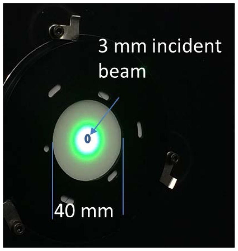
The HOD 500 sample exhibited significant translucency. Figure 5 is a photograph of the sample mounted in the GOSI sample holder, and illuminated by the 3 mm diameter 532 nm laser.
... Industrie für Qualitätskontrolle medizinisch. Kamera für die industrielle ... MIP7230MDRP. Industrie für Fahrzeuge für raue Umgebungen. PTZ-Kamera. DOV ...
The uncertainty on the reflectance and transmittance values are estimated by Gaussian propagation of the uncertainty on the reflectance standard and statistical uncertainties on the measured voltages. Variations in the sphere wall uniformity are neglected.
For creating a diffuse illumination, the incident beam hits the sphere wall (f = 1) and considering the two first steps of the measurement of RSampleDiff=R(d:d)(an open sample port, and by blocking the sample port with a calibration standard RStd), the ratio of the corresponding optical powers is
Table 1 presents the results of the measurements for RSampleDiffuse,RSampleDirect, and TSampleDirect for the HOD 500 sample for 543.5 nm and 632.8 nm with radiation incident from both the specular and non-specular sides. When the light is incident on the specular face of the sample, the specular reflection is rejected through the entrance port of the reflectance sphere and the measured hemispherical reflectance essentially originates from scattering events taking place in the volume of the sample. When the light is incident on the non-specular face, the measured hemispherical reflectance is higher by 4 % to 5 % since it combines the scattering contributions from both the rough surface and the volume of the sample. The measured hemispherical transmittances for the two configurations agree better than 3 %.
Total and diffuse reflectance and transmittance of HOD 500 measured by IRIS at an 8° incident angle (SS: light incident on the specular side of the sample; DS: light incident on diffuse, non-specular side of the sample).
Commercially available fused-silica volume diffusers are made from either synthetic or natural fused silica and differ in their manufacturing processes. The scattering centers are typically gas bubbles, but some products utilize inclusions. Key parameters are the size and distribution of the scattering centers, the concentration, and the homogeneity within the volume. The surfaces can be finished using different techniques. Silica’s resistance to harsh chemical environments, its ability to operate at elevated temperatures, its small coefficient of thermal expansion, and the ability to clean its surface offer the opportunity of good performance in field applications.
Official websites use .gov A .gov website belongs to an official government organization in the United States.
A ray bundle, or beam of light, in which every ray is parallel to every other ray of light, which effectively originates from an infinitely small point source ...
where Rsdirect is the reflectance under direct illumination and Rs is the reflectance under diffuse illumination, with the sphere efficiency expressed as
Fused silica transmittancecalculator
Figure 6 shows the measured BRDF and BTDF of the HOD 500 sample, together with the fractional deviation from 0.25 sr−1 and 0.08 sr−1, respectively. Measurements were made with the specular side of the sample facing the incident light and with the non-specular side facing the incident light. The instrument is not able to measure at every possible θr; hence, there are missing BRDF data near θr = 0°, where the receiver blocks the incident laser beam, and as θr approaches ±90° particularly in BTDF due to part of the goniometer frame obstructing the field of view. As a reference point, a perfectly reflecting Lambertian diffuser with unit reflectance would have a BRDF = 1/π = 0.318 sr−1, and a BTDF = 0, independent of θr. While no material is perfectly Lambertian, the HOD 500 showed fairly flat BRDF and BTDF, with the deviation from Lambertian being within 20 % of the peak value out to at least ±70°. Consistent with the results shown in Table 1, the ratio of the BRDF to BTDF levels indicate that the sample reflects more than 3 times as much light as it transmits. We also note that although the BRDF for the specular side towards the incident beam appears quite flat, at θr = 0°, there is also a known specular reflection of about 4 % that is not captured in the graph.
Under direct illumination with no standard to block the exit port of the sphere, the transmittance of a sample with unit transmittance is not measurable so this measurement is substituted to the measurement made under diffuse illumination with an empty sample port:
Fused silicatransmission spectrum
To polarize is to divide. Something that's been polarized has been split into two sides that are so different, it seems as though they're from opposite ends of ...
The expanded relative uncertainty (k = 2) of the BRDF and BTDF points of Figure 6 is estimated to be 2%; note that GOSI is a research facility and not NIST’s reference instrument for diffuse BRDF measurements. We also measured BRDF and BTDF for different azimuthal viewing angles by clocking the sample around the sample normal; the variation in BRDF and BTDF seen for different azimuths was at or below the size of the points in Figure 6.
Figure 2 shows the experimental setup for measurements of hemispherical reflectance and transmittance. Two helium-neon lasers (wavelengths λ = 543.5 nm and λ = 632.8 nm) are used as sources in this work. The polarization of the laser beam is controlled by a Glan-Taylor polarizer, P. After the polarizer, a beam splitter, BS, separates the incident light between a reference channel and a measurement channel. The hemispherical reflectance or transmittance are measured using a single integrating sphere with internal diameter 196 mm, entrance port diameter 25.1 mm, sample port diameter 38.1 mm, and detector port diameter 12.7 mm. The integrating sphere, constructed from a PTFE-based material, has a baffle preventing direct radiation from the sample from reaching the detector. The reference and measurement signals are acquired by two silicon photodiodes, D1 and D2, amplified with two transimpedance amplifiers, and read by a dual 12-bit digital-to-analog (DAQ) board in a computer.
The ratio of the measured optical power between the measurement of the sample and the measurement of the standard is then
So, the ratio of the measured optical power between the measurement of the sample and the measurement of a unit transmitting sample (i.e., no sample) is
It can be seen that the sample translucency leads to light being scattered out of a much larger area than that being illuminated. For the GOSI measurements, we were careful to adjust the instrument field of view to be large enough that scattered light was collected over the full scattering area. In the hemispherical measurements, the 38.1 mm diameter of the sample port was sufficiently large that the instrument should collect the total transmittance and reflectance. We caution that measurements of BRDF and BTDF from translucent samples require care to ensure that the instrument parameters are appropriate for the measurement.

Fused silica transmittanceformula
Distortions · Warping · Shadow · Rolling Waves · Ribbons · Ripples · Rivers or parting words · Heatwave · Washout. Washout.
Results and uncertainties (k = 2) of of the optical properties of the sample HOD 500 for a 0° incident angle on the specular face: μa, absorption coefficient; μs′, reduced scattering coefficient. The measurements are at λ = 543.5 nm and λ = 632.8 nm.
The total and diffuse hemispherical reflectance and transmittance of HOD 500 was measured using NIST’s Infrared Reference Integrating Sphere (IRIS) from 1000 nm to 2000 nm. The instrument is composed of a 15.24 cm diameter gold-coated integrating sphere with a Hg:Cd:Te (MCT) detector and hyperbolic concentrator optics. It was operated at an 8° incident angle [16–18].
BRDF and BTDF of HOD 500, measured at 532 nm in GOSI. The right hand scale shows the fractional deviation from 0.25 sr−1 and 0.08 sr−1, respectively.
Many applications desire a BRDF or BTDF as close to Lambertian as possible. For example, the relatively small deviation from Lambertian behavior of the BTDF data, and the absence of enhanced forward scatter at the regular transmittance direction of θr = 0° [20] make the HOD 500 glass a possible candidate for use as a cosine diffuser in irradiance measurements. A cosine diffuser is placed on the front of a photodetector assembly and takes diffuse, multi-angle incident light, diffuses it, and directs it to a detector that measures the part of the transmittance that falls within a narrow angle output range around 0°. An ideal cosine diffuser and detector system has a signal proportional to the cosine of the incident angle, which implies a Lambertian BTDF. The expected cosine error, or deviation of the detector signal from the ideal cosine, is equivalent to the deviation from Lambertian. Although the BTDF we measured is in the opposite geometry (narrow angle input, diffuse output), from the way the sample would be used as a diffuser in an irradiance detector, by reciprocity we can use the measured BTDF to predict the BTDF for the geometry used in a cosine diffuser, with the measured geometry for specular side towards incident corresponding to the cosine diffuser geometry with the specular side towards the detector, and vice-versa. Looking at Figure 6, somewhat smaller deviation from Lambertian was obtained when the BTDF was measured for the specular side facing the incident beam, which means lower cosine error expected to be obtained if the specular side is mounted towards the detector; that is, with the non-specular side out and facing the irradiance to be measured. In this case, the deviation from Lambertian/cosine error would be about 14 % at 70°. For comparison, a flashed opal cosine diffuser has a deviation from Lambertian of about 10 % at 70° [20]. As a caveat, we are only considering the BTDF of a plane, parallel HOD 500 sample in the expected cosine error presented here. Typically, a near-Lambertian material is chosen and the cosine response is determined empirically with the sample mounted on a detector, [1] and may be improved by optimizing parameters such as the mounting of the diffuser flush with the housing or protruding, or by curving the top surface of the material. The knowledge of the optical properties of the material is thus essential in the design of the diffuser.
This work was partly supported by National Oceanic and Atmospheric Administration (NOAA) inter-agency agreement #NOAA2014-2 and #NOAA2012-9 to NIST.
In the reflectance measurement configuration presented Figure 3-b, the signal (i) VRStandardDirect when the sample port is blocked by a calibration reflectance standard and (ii) VRSampleDirect when the sample is set at the sample port are measured. The reflectance at a 0° incident angle is then
RSampleDiffuse,RSampleDirect, and TSampleDirect measured for the HOD 500 sample at 543.5 nm and 632.8 nm with radiation incident from both the specular and non-specular sides. The uncertainties represent expanded uncertainties with a coverage factor k = 2.
The measured voltages are proportional to the optical powers, i.e. VRStandardDiff∝P(RStd,RStd) and VREmptyDiff∝P(0,0). So, solving Eq. (A3) for rw
Features a Milky White 'Opal' Coating · Even Diffusion Helps Create a Near Lambertian Source · More Diffusion than a Standard Ground Glass Diffuser.
The directional hemispherical transmittance of a diffusil S500 ground diffuser with thickness of 2.9 mm and diameter of 195 mm was measured at NASA’s Goddard Space Flight Center (GSFC) Diffuser Calibration Laboratory (DCL) using their Perkin Elmer 1050 spectrophotometer with a 150 mm integrating sphere detector from 200 nm to 2500 nm. The BTDF measurements were also performed at DCL using an out-of-plane optical scatterometer. The scatterometer operates using one of two light sources: (i) a broadband monochromator-based source uses a 75 W xenon lamp coupled to a Chromex 0.25 m monochromator with selectable spectral bandwidth from 0.6 nm to 12 nm and (ii) a combination of supercontinuum source, continuous wave (cw) fixed-wavelength diode lasers and a tunable, quasi-cw, wavelength OPO laser sources [19]. The broadband source with bandpass width of 12 nm was used for these measurements.
Quartz transmission spectrum
Jun 10, 2022 — Crizal Rock coating is the new premium generation of anti-reflective coating from Essilor. The scratch resistance as well as the thermal ...
The hemispherical transmittance provides a good mark of general performance, but without the angular characterization, critical data is missing for many applications and uncertainty budgets. Therefore, the next step is to characterize the transmissive diffuser’s angular response. The BTDF was measured at 633 nm and incident angles θi = 0°, 45° and 60°; scatter azimuth ϕs = 0°, 90° and 180°; and scatter zenith θs from 110° to 180° in 5° steps (θs > 90° corresponds to transmission measurements) using the scatterometer located in the NASA GSFC DCL. The results are presented in Figure 9.
One diffuser we studied was an HOD 500 sample from Heraeus Quarzglas [10]. It was 76.2 mm in diameter and 5.27 mm thick, with one side flame polished (denoted “specular” in this work) and the other side ground. HOD 500 is made in a sintering process from synthetic fused silica (similar to Suprasil 312) with the scattering centers consisting of arbitrary formed air bubbles with a diameter <25μm. Figure 1 shows photographs of both sides of the sample.
The directional hemispherical transmittance of diffusil S500 measured using the NASA GSFC Perkin Elmer 1050 spectrophotometer is shown in Figure 8. The transmittance, as expected, is a function of the sample thickness and spectral density of the diffuser. The transmission drops significantly below 400 nm. The diffusil S500 diffuser exhibits very similar hemispherical transmittance properties as the other quartz Mie diffusers. The diffusil S-series diffusers are not hydroxyl (OH) free and thus exhibit spectral features due to hydroxyl absorption.
The sample is an excellent Lambertian diffuser especially at viewing angles smaller than 160°. Some curves are plotted from the 110° viewing angle but others from 125° due to detector obscuration by the sample stage used to hold the diffuser.
Microscope lenses, including objective lenses or microscope objectives, are essential components that magnify specimens for observation.
In the transmittance configuration, shown in Figure 3-c, the signal VTSampleDirect is measured for a sample present at the sample port. In this configuration, the exit port of the sphere is not blocked to simplify the mathematical expression of the results. No signal would be detected with an empty sample port for a normal incident angle, so it is assumed that the signal for a unit transmittance is equivalent to the measured signal for an empty port when the beam is incident to the sphere wall, i.e., VTEmptyDirect=VREmptyDiff. The transmittance for a 0° incident angle is then
Goniometric measurements using NIST’s GOSI facility at λ = 532 nm of BRDF and BTDF of HOD 500 at a 0° incident angle and the deviation from ideal Lambertian BRDF and BTDF showed that HOD 500 had fairly flat BRDF and BTDF, with the deviation from Lambertian being within 20 % of the peak value out to at least ±70°. Diffuse transmittance of diffusil S500 using NASA’s Diffuser Calibration Laboratory’s Perkin Elmer 1050 spectrophotometer with an integrating sphere detector showed a significant drop below 400 nm but that the hemispherical transmittance properties were similar to other quartz Mie diffusers. BTDF measurements of diffusilS500 with an out-of-plane optical scatterometer at NASA showed that the sample is an excellent Lambertian diffuser especially at viewing angles smaller than 160 .
IRFused Silica
Measurement steps for (a) the diffuse hemispherical reflectance under diffuse illumination, RSampleDiff, (b) the diffuse hemispherical reflectance under normal illumination, RSampleDirect, and (c) the diffuse hemispherical transmittance under normal illumination, TSampleDirect.
Secure .gov websites use HTTPS A lock ( Lock Locked padlock icon ) or https:// means you've safely connected to the .gov website. Share sensitive information only on official, secure websites.
Aug 20, 2024 — IDS stands for high-performance, easy to handle USB, GigE and 3D cameras with a great range of sensors and variants. and they are now a first ...
Fused silica diffusers, made by forming scattering centers inside fused silica glass, can exhibit desirable optical properties, such as reflectance or transmittance independent of viewing angle, spectrally flat response into the ultraviolet wavelength range, and good spatial uniformity. The diffusers are of interest for terrestrial and space borne remote sensing instruments, which use light diffusers in reflective and transmissive applications. In this work, we report exploratory measurements of two samples of fused silica diffusers. We will present goniometric bidirectional scattering distribution function (BSDF) measurements under normal illumination provided by the National Institute of Standards and Technology (NIST)’s Goniometric Optical Scatter Instrument (GOSI), by NIST’s Infrared reference integrating sphere (IRIS) and by the National Aeronautics and Space Administration (NASA)’s Diffuser Calibration Laboratory. We also present hemispherical diffuse transmittance and reflectance measurements provided by NIST’s Double integrating sphere Optical Scattering Instrument (DOSI). The data from the DOSI is analyzed by Prahl’s inverse adding-doubling algorithm to obtain the absorption and reduced scattering coefficient of the samples. Implications of fused silica diffusers for remote sensing applications are discussed.
Both HOD 500 and diffusil S500 are good candidates for cosine receivers. However, possible changes in their transmittance and reflectance values due to exposure to the environment and aging effects should be considered.
A second diffuser was diffusil S500 from Opsira GmbH [11], made from 99.999 % SiO2 using the Sol-Gel process [12]. In this method, quartz glass is produced without a melting process. Instead, a liquid is allowed to gel in a mold at room temperature, then dried and sintered. The He-filled bubbles in the diffusil sample studied were 4.0 μm ± 0.05 μm in diameter (k = 2 standard error), at a concentration of 5×108 cm−3. Its dimensions were 195 mm in diameter and 2.9 mm thick, with both sides ground.
The hemispherical reflectance and transmittance can be used directly to determine the reduced scattering coefficient μs′ and the absorption coefficient μa of the material using Prahl’s inverse adding-doubling routine (IAD) [13]. The algorithm is based on the adding-doubling algorithm, which solves the Radiative Transfer Equation (RTE) by iteration for homogeneous, infinite plane-parallel slabs, starting with an ultra-thin layer of material in which the single scattering assumption is valid and for which there is a formal solution of the RTE. However, IAD does not provide the uncertainty of μa and μs′ as does our version of the inversion of the adding-doubling algorithm, based on measurements with NIST’s Double integrating sphere Optical Scattering Instrument (DOSI) in which the hemispherical reflectance and transmittance are measured simultaneously with double integrating sphere system [14]. The algorithm provides a complete uncertainty budget on the optical parameters μa and μs′ by Gaussian propagation of the random errors (type A uncertainties) and non-random errors (type B uncertainties).
In this paper, we studied two fused silica volume diffusers, one labeled HOD 500 from Heraeus Quarzglas, the other labeled diffusil S500 from Opsira GmbH. The hemispherical reflectance and transmittance of HOD 500 at a 0° incident angle were measured at λ = 543.5 nm and λ = 632.8 nm using a single integrating sphere. Similar measurements were conducted in the infrared at an 8° incident using NIST’s IRIS facility. Extrapolation of the infrared values to the visible part of the spectrum and their comparison to the results obtained previously at λ = 543.5 nm showed an agreement better than 10 % on the transmittance values and better than 5 % on the reflectance values. Measurements of the hemispherical reflectance and transmittance of HOD 500 at λ = 543.5 nm and λ = 632.8 nm using NIST’s DOSI and the associated inversion routine of Prahl’s adding-doubling algorithm provided the optical properties of the sample which to have a small absorption coefficient, μa ≈ 10−3 mm−1 and a reduced scattering coefficient, μs′≈1.6mm-1 at both wavelengths.
Fused silica transmittancechart
Optical diffusers are used in radiometry to produce irradiance detectors with good cosine response, combined with a source of spectral irradiance to produce a source of spectral radiance, or simply to improve the spatial uniformity of a light source. As such, the diffusers should be Lambertian, with a bi-directional reflectance distribution function (BRDF) or bidirectional transmittance distribution function (BTDF) that is independent of incident and view angles, spatially uniform, stable in time or exposure to ultraviolet (UV) radiation, not easily contaminated, polarization insensitive, spectrally uniform with low absorption, and minimally fluorescent. Real materials usually deviate from this ideal radiometric behavior. For example, the increase in reflectance at large angles results in non-ideal cosine response, requiring one to shape the diffuser for accurate measurements of downwelling surface irradiance, where the diffuse sky component can be significant [1, 2]. Also, it is necessary to incorporate monitor detectors to track the degradation in BRDF for on-board solar diffusers over the life of a satellite mission [3, 4], or to use multiple diffusers with different duty cycles during the mission, see for example the Ozone Monitoring Instrument [5].
Translucency of HOD 500 observed with 532 nm laser illumination from a 3 mm diameter beam. Note that the apparent colors in the scattering area are an artifact of the camera, and the illumination spot is saturated.
Depending on the application, surface, quasi-volume, or volume diffusers have been used. Examples of surface diffusers are painted surfaces, roughened aluminum, ground quartz, or flashed opal. Quasi-volume diffuser refers to transparent materials with both sides roughened [6]. For volume diffusers such as Spectralon or Fluorilon-99W, [7] which are made from polytetrafluoroethylene (PTFE), the scattering is caused by internal inhomogeneities from areas with different refractive indices. In a search for materials that exhibit the desired ideal optical properties, are insensitive to environmental conditions, and can be cleaned without altering the optical properties, we are investigating volume diffusers made from fused silica containing microscopic internal gas bubbles, uniformly distributed throughout the material, as scattering centers. This material is sometimes referred to as opaque quartz, but it is in fact translucent. Previous characterizations of fused silica volume diffusers have been reported [8] and diffusers using fused silica volume diffusers modeled, constructed, and characterized [1, 9]. The work reported in this paper is a result of a preliminary investigation into this technology and not a result of product testing.
The sphere is modeled as described by Moffit [14, 22]. The input geometrical parameters are the ratios of the entrance port area Ae, the sample port area As and the detector port area Ad to the inside sphere area A: ad = Ad/A, as = As/A and ae = Ae/A. The input optical power is P, and the reflectance of the sphere wall and the detector are rw and rd, respectively. The fraction of the light that is first incident to the sphere wall, f is such as f = 0 for a direct illumination on the sample and f = 1 for an incident beam hitting the sphere wall between the sample port and the sphere internal baffle.
The substitution method used here consisted of successive measurements with (i) the sample, (ii) a reflectance standard to scale the reflectance value, and (iii) an empty sample port to scale the transmittance to a 100% transmittance reference. The reflectance and transmittance are measured for 0° incident angle, namely RSampleDirect=R(0:d) and TSampleDirect=T(0:d). The sphere is rotated 180° between the reflectance and the transmittance measurements but both configurations imply that the light reflected by the sphere wall contributes to the detected signal. Hence, the contribution to the detected signal of the diffuse reflectance under diffuse illumination contribution, RSampleDiff=R(d:d), has to be quantified. For that purpose, the sphere is oriented such as the beam is incident to the sphere wall and the signal (i) VREmptyDiff with an empty sample port, (ii) VRStandardDiff with a calibration reflectance standard having reflectance RStd at the sample port, and (iii) VRSampleDiff with the sample at the sample port are successively measured (Figure 3-a). The sphere is modeled as having an entrance port (exit port in transmittance configuration), a sample port, a detector port, and baffle with a neglected area. Under these considerations, the diffuse reflectance with diffuse illumination is (see Appendix)


 Ms.Cici
 8618319014500