
High-performance multiphoton excitation microscope using ... - multiphoton excitation microscope
by E Baghdasaryan — All content on Eyewiki is protected by copyright law and the Terms of Service. This content may not be reproduced, copied, or put into any artificial ...
LensEFL
Since one surface has twice the radius of the other and since one surface is convex to the incoming light while the other is concave, we can write,
Light consists of a continuous spectrum of many wavelengths, representing different colors. Often, the inclusion of an inappropriately wide range of wavelengths of light during imaging experiments can lead to various issues such as artifacts, crosstalk, bleed through, specimen damage/phototoxicity and low image contrast, but too narrow a range can lead to low signal intensity.
Acoustic based filters consist of a birefringent crystal; application of an oscillating radio frequency (RF) alters the refractive index and thus diffraction properties of the crystal. Changing the RF changes the wavelength of light that is diffracted, enabling rapid wavelength tuning.
Filters are inserted into the light path at differing points dependent upon their function. One of the most common uses of filters in fluorescent imaging applications is to separate different wavelengths of light to permit the selective excitation of specific fluorophores, and the subsequent separation of the emission and excitation light, to permit high contrast imaging. In a properly configured microscope, only the emission light should reach the detector, so that the resulting fluorescence structures have high contrast against a very dark or black background. Correct filtering is essential to ensure this.
In addition, in order to differentiate between shortpass, longpass and bandpass filters, filters are denoted SP (or KP from kante, German word for edge), LP (or L) and BP (or B) respectively.
Double convex lensformula
Filters can also normally only pass either short wavelengths, long wavelengths, or a band between long and short wavelengths and these are termed and defined as follows:
Nov 30, 2022 — The Many Steps of Fabricating a PIC · Grow or deposit your chip material · Print a pattern on the material · Etch the printed pattern into your ...
Focal Length & Ratio Useful calculators and formulae. Focal Length Calculator. Calculate the focal length of your telescope. Formula: Aperture X Focal Ratio.
These highly efficient filter sets provide maximum attenuation of excitation light in the detection pathway, in parallel with the successful capture of as many emitted photons as possible. High detection efficiency enables a corresponding reduction in illumination level and thus reduction of phototoxicity to the specimen.

As well as individual filter sets, there are also dual- and triple-band filters available which allow simultaneous imaging from multiple fluorophores. For example, the DAPI-FITC-TRITC filter combinations allow for the simultaneous detection of these or other fluorophores that have similar spectral characteristics. Care must be taken however to ensure that the excitation of any included fluorophore overlaps as little as possible with the transmitted emission wavelength range of another - this would lead to what is known as 'crosstalk', where excitation light unintentionally reaches the detector.
The eyepiece has a field of view of 52°, so the field of view for the telescope at this magnification will be 52 ÷ 30 = 1.7°.
Figure 3: Example of a filter cube and how light interacts with the various components. White light enters the filter cube at the excitation filter (blue) which selectively passes wavelengths required to excite the fluorophore of interest. The transmitted light then interacts with the dichroic (yellow), where it is reflected with high efficiency toward the sample. The fluorophores are excited and emit a characteristic wavelength that is longer than that of the excitation light and, along with reflected excitation light, returns back to the filter cube. Now, the dichroic reflects backscattered light away from the detector, while transmitted the longer wavelength emission light. The light is then filtered again with an emission filter (red) prior to detection.
A double-convex lens is to be made of glass with an index of refraction of 1.5.One surface is to have twice the radius of curvature of the other and the focal length is to be 60mm. What is the (a) smaller and (b) larger radius?
Plano-convexlens
Figure 4: Spectral diagram of excitation, dichroic and emission filters in a filter cube designed to image the dye Alexa Fluor 488. Graph showing the excitation (green dash) and emission (green) spectra of Alexa Fluor 488. The transmission wavelengths of the excitation bandpass filter (blue), the dichroic (orange), and the emission bandpass filters (green) are indicated. Adapted from ThermoFisher spectraviewer.
To give an example of this: A hypothetical BP filter is a combination of short pass (550 nm) and long pass (500 nm) would individually be termed SP550 and LP500, but when describing a BP filter combination, it would be labeled as BP 525d25. This indicates a bandpass centered at 525 nm with 25 nm transmission permitted to either side.
An object is placed against the center of a thin lens and then moved away from it along the central axis as the image distance is measured. Figure 34-41 gives i versus object distance p out to ps=60cm. What is the image distancewhen p=100cm?
Filters are optical components that transmit specific wavelengths of light while attenuating or blocking others. The attenuation level of filters is described in optical density, due to the variety of different methods available for blocking light. The different methods used depend upon the type of filter, of which there are three main types, absorption, interference, and acoustic.
A common issue with filters is knowing how to orient them in the light path. For simplification and ease of use, filters are usually matched and combined to make a filter cube (Fig.3). Filter cubes, therefore, consist of an excitation filter, a dichroic and a barrier filter correctly orientated in order to permit fluorescence imaging of specific wavelengths of light, whilst removing any interference or artifact from other sources, such as the excitation light.
An example spectral diagram of an Alexa Fluor 488 filter cube is shown in Fig.4. The excitation and emission spectra of Alexa Fluor 488 are shown, and the corresponding excitation, emission and dichroic filters that are specifically matched for imaging this fluorophore are shown.
Most optical filters are interference filters, which are based on the principle of the Fabry-Perot interferometer (or etalon). These multi-layer devices are made of microscopically thin layers of material composed of varying types of glass or fused silica, with each having two reflecting surfaces or mirrors. The peak wavelength transmission corresponds to the resonance of the etalon (Fig.1). Multiple etalon layers of different optical path lengths are included to transmit a broader range of wavelengths, and the bandwidth of a filter is determined by the number of these layers. The use of interference-based filters in microscopy has increased substantially due to the high level of selectivity and transmission when compared to glass counterparts.
Often filter names include numbers too. As the most common unit for describing filters the wavelength of light in nm, this is used to describe the filters properties. For a BP filter the central wavelength (CWL) at 50% of peak transmission is used, often followed by bandwith. For a LP filter, the number used would be the 'cut-on' wavelength. For a SP filter this would be the 'cut-off' wavelength, which is the point where the filter switches from transmitting to reflecting and is transmitting 50% of the peak transmission.
In this article different filters will be introduced and discussed in detail to inform microscopy users on the types of filters available and how to correctly identify the filter they need.
Microscopy filters act to modify the light within an optical imaging system. This can be for observation purposes or for capturing high-quality images using a detector.
Double convex lensdrawing
Interference based filters consist of several carefully designed layers that selectively transmit wavelengths based on the interference effects that occur between the incident and reflected waves at the layer boundaries.
Optical lenses
The FLIR Blackfly S BFS-PGE-123S6P-C color camera offers 12.3 MP, 10 FPS, and a Sony IMX253MZR 1.1" CMOS sensor.
On July 30, 2024, Thomas Mayr and Urs Imholz, representing Sigrist-Photometer, handed over a LabScat 2 measuring device to the leading training institute ...
With both automatic and precise manual control over image capture and on-camera pre-processing, the Blackfly S accelerates application development. FEATURES THE ...
During a fluorescent acquisition, light of a specific wavelength is generated by passing multispectral light from a light source through the excitation filter, selectively passing the desired excitation wavelengths. Wavelengths that pass through the excitation filter then reflect off the surface of the dichroic mirror, which is tilted at a 45° angle to the excitation light, through the objective lens to the sample, exciting fluorophores that have an excitation spectrum correlating to the wavelength of the light.
Asphericlensthorlabs
Optical filter sets that are used in fluorescence acquisitions are designed around the major wavelengths used in fluorescence applications, which is based around the most used fluorophores. For this reason, cubes are often named after the fluorophore they are intended for imaging, such as DAPI (blue), FITC (green) or TRITC (red) filter cubes. These filter cubes are placed in the light path and filter the light selectively to permit high contrast fluorescent imaging. Filters inside filter cubes from different manufacturers are most often not interchangeable.
Explore a wide range of our Germanium Window selection. Find top brands, exclusive offers, and unbeatable prices on eBay. Shop now for fast shipping and ...
50 through 57 55, 57 53 Thin lenses. Object Ostands on the central axis of a thin symmetric lens. For this situation, each problem in Table 34-6 gives object distance p (centimeters), the type of lens (C stands for converging and D for diverging), and then the distance (centimeters, without proper sign) between a focal point and the lens. Find (a) the image distance localid="1662982946717" iand (b) the lateral magnification m of the object, including signs. Also, determine whether the image is (c) real (R) or virtual (V) , (d) inverted (I) from object O or non inverted (NI), and (e) on the same side of the lens as object Oor on the opposite side.
There are a lot of unusual conventions for filter names that can be confusing. Likewise, many manufacturers adopt their own nomenclature. As mentioned, the three main classes are excitation filters, emission/barrier filters, and dichroic filters, but filters can also be categorized as SP, LP or BP. Commonly, filters are referred to by these characteristics and the wavelength where they switch between transmission to reflection.
Concavo-convexlens
There are other types of filters that are available for microscopy applications. The following list indicates their name and uses:

Figure 34-27 is an overhead view of a mirror maze based on floor sections that are equilateral triangles. Every wall within the maze is mirrored. If you stand at entrance x, (a) which of the maze monsters a, b, and chiding in the maze can you see along the virtual hallways extending from entrance x; (b) how many times does each visible monster appear in a hallway; and (c) what is at the far end of a hallway?
Infraredlens
A corner reflector, much used in the optical, microwave, and other applications, consists of three plane mirrors fastened together to form the corner of a cube. Show that after three reflections, an incident ray is returned with its direction exactly reversed.
The light microscope remains one of the most used tools for research, particularly in the fields of biological or biophysical sciences and offers a means to observe the dynamics of cellular processes. A critical component of these methods lies in obtaining the best possible sample representation, whilst simultaneously minimizing specimen damage, artifacts, and uncertainty.
An object is placed against the center of a converging lens and then moved along the central axis until it is 5.0mfrom the lens. During the motion, the distance between the lens and the image it produces is measured. The procedure is then repeated with a diverging lens. Which of the curves in Fig. 34-28 best gives versus the object distance p for these lenses? (Curve 1 consists of two segments. Curve 3 is straight.)
These are relatively inexpensive, stable and long-lived under normal conditions. These filters are usually made from colored glass or gelatin sandwiched between two glass plates. However, they are generally limited to a small selection of colors, they offer a low peak transmittance and little flexibility in available thickness. The absorption process also converts the radiant energy into heat, which can lead to the glass cracking under intense illumination.
The modern microscope forms a central tool in scientific research and a lot of effort is directed towards maximizing the information gleaned from microscopy experiments. A critical part of microscopy is ensuring that a sample receives the correct illumination light, to ensure a fluorophore is excited efficiently and the largest number of photons are emitted. Not only this, but also to ensure that as many of these photos are captured as efficiently as possible, whilst simultaneously removing unwanted light and minimizing sample exposure and thus limiting fluorophore destruction.
The three most common types of filters used for color selection in fluorescence microscopy are excitation filters, barrier filters and dichroic beam splitters. In modern microscopes, these are typically interference-based filters.
Absorption based filters normally consist of colored glass which selectively absorbs wavelengths of light and transfers the energy into heat.
Acoustic based filters, also known as acoustic-optic tunable filters (AOTF) are increasingly being incorporated into microscopy applications as they do not suffer mechanical constraints, speed limitations and can easily accommodate a lot of different laser systems and output wavelengths. These are generally restricted to well-collimated light sources. Several limitations exist with AOTFs, including their inability to work with sub-450 nm wavelengths, and that thermal effects can modify the refractive index of the crystal until stability is achieved.
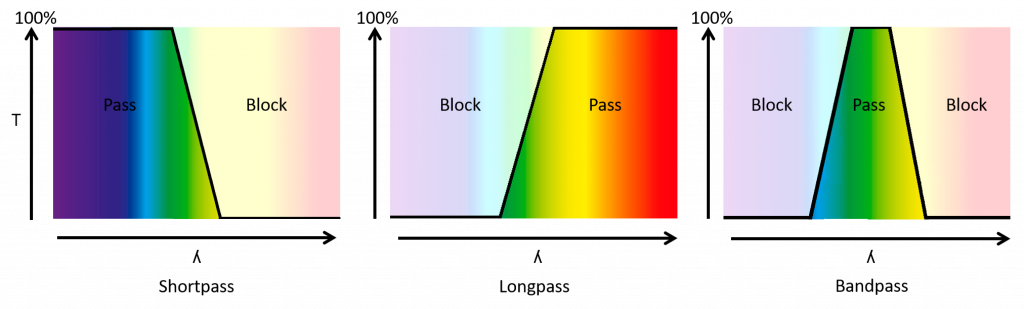
Figure 2: Plots of how transmittance varies with wavelength for SP, LP and BP filters. Transmitted light is shown in bright colors and attenuated light shown as faded. For a SP filter, shorter wavelengths are transmitted while light with longer wavelengths are blocked, vice versa for LP filters. In BP filters, a combination of SP and LP filter characteristics only transmit a band of light wavelengths, such as green light in this example. The slope of the filter is the gradient of the curve between the transmitted and blocked wavelengths. This makes SP transmit blue/green, LP transmit yellow/red and BP transmit any band, but typically green.
To prevent this, it is important to selectively filter out specific wavelengths of light and transmit others to increase the quality of the resulting image as well as minimize unwanted specimen damage. Without filters, a detector would not be able to distinguish fluorescence emission from excitation light and autofluorescence in the sample. Determining which filters are needed and how they should be configured and introduced into the light path is, therefore, an essential component of acquiring high-quality images.
Figure 1: Principle of interference filters (based on the etalon). Light enters the etalon (black) and goes through multiple reflections/refractions/transmittance depending on color (blue and red), the interference of the light emerging from the etalon during each bounce causes a modulation in the transmitted and reflected beams
Pinhole Size Calculator. This tool calculates the optimal size of a pinhole that is a given distance away from the sensor / film of your camera. See the article ...
Binoculars are a pair of hand-held identical telescopes which allows the user to see easily see distant objects in a three-dimensional viewpoint.
Filters provide a means of efficiently filtering the light that passes through the system, mostly in the form of fluorescent filter cubes. These cubes are specifically designed for one or several fluorophores of interest and are an essential component to high-quality fluorescent imaging. Ensuring that the correct combinations of filters are incorporated into the system (and in the correct place) can maximize image quality and minimize specimen damage. Likewise, other types of filters are often incorporated into microscopes based on specific individual needs. These can include beamsplitters to permit imaging with multiple wavelengths simultaneously, polarizing filters, permitting polarized light microscopy, ND filters reducing multispectral light intensity, filters to remove harmful IR or UV rays as well as other filters used to enhance the image quality such as didymium filters and yellow filters.
Following excitation, fluorophores will emit light of a longer wavelength when compared to the excitation light, this emission light is gathered by the objective lens, and passes back toward the dichroic mirror, where it can pass through (due to the longer wavelength). The unwanted scattered excitation light is reflected towards the light source. The emission light, prior to hitting the detector, is then filtered by an emission filter that removes any residual unwanted light (such as autofluorescence).
Although historically SP and LP filters were used, most modern filters are BP filters due to the additional control over wavelength. Most fluorophores in fluorescent microscopy have very well-defined bands of excitation and emission profiles, so BP filters work very well for selectively permitting the passage of excitation light and emission light for improved signal generation and collection.


 Ms.Cici
 8618319014500