
HeNe Lasers: Pros and Cons - he ne laser
Objective lensmicroscopefunction
3. Parry-Hill, M.J., Vogt, K.M, Griffin J.D., and Davidson, M.W. Matching Camera to Microscope Resolution in the MicroscopyU website (https://www.microscopyu.com/tutorials/matching-camera-to-microscope-resolution)
Instead of reducing the aperture to limit light, the photographer can add a ND filter to limit light, and can then set the shutter speed according to the particular motion desired (blur of water movement, for example) and the aperture set as needed (small aperture for maximal sharpness or large aperture for narrow depth of field (subject in focus and background out of focus)). Using a digital camera, the photographer can see the image right away and choose the best ND filter to use for the scene being captured by first knowing the best aperture to use for maximal sharpness desired. The shutter speed would be selected by finding the desired blur from subject movement. The camera would be set up for these in manual mode, and then the overall exposure adjusted darker by adjusting either aperture or shutter speed, noting the number of stops needed to bring the exposure to that which is desired. That offset would then be the amount of stops needed in the ND filter to use for that scene.
... read. The rectangular lens with 2.5X magnification is designed for long-term readings. Magnifying glass size 24 x 16 cm. This versatile reading magnifier can ...
Most microscopes have optical exit ports with a diameter of around 18-25 mm. Using no magnification (1x objective), the image would, therefore, cover 18-25 mm of the sample. Given the fixed size of the image, camera sensors with diagonal dimensions greater than the microscope camera port would have pixels with no light falling on them. Therefore, it is important to match the field of view of the camera with the maximum field of view of the microscope.
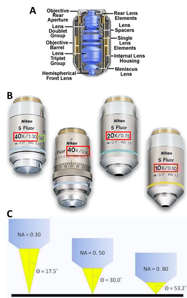
The aperture stop is the part of the imaging system that limits the range of angles of light the lens can collect from the sample. This range of angles defines the lens NA and therefore the system resolution, the ability to detect two objects as different. Most microscope objectives are designed such that the aperture stop is the Objective Rear Aperture, as seen in Fig.3A. This ensures that the objective defines the system resolution and that the resolution is the same across the entire field of view.
2. Davidson, M.W. Koehler Illumination in the Zeiss Basic Resources website (https://w ww.zeiss.com/microscopy/us/solutions/reference/basic-microscopy/koehler-illumination.html)
Microscope objectives contain lenses but are not as simple as the lenses seen in Fig.2, making them complex lenses (Fig.3A). While the overall effect can be magnification, these lenses are carefully designed to control a variety of aspects of lenses, such as working distance, and the ability to correct problems such as aberrations. Objectives are characterized by two factors: magnification and numerical aperture (NA). Objective magnification ranges from 2x to 100x (and is combined with the eyepiece magnification), magnifying the sample 2-fold to 100-fold respectively (Fig.3B). NA is related to the focal length of the lens, namely what angle light exits/enters the objective, as this affects the resolution (Fig.3C, read our app note on resolution and NA for more). See Fig.3 for more information.
The output of most microscopes is an image about 2 cm across, so this is typically magnified again in order to fill the field of view of the eyes. Eyepieces, another magnification system, give between 10x to 30x magnification on top of that provided by the objective and microscope. In combination with the lens in the eye, this magnifies the image to the retina at a useful scale, so that the human eye may resolve and observe objects even as small as cells (~10 µm).
NCI's Dictionary of Cancer Terms provides easy-to-understand definitions for words and phrases related to cancer and medicine.
The advantage of this approach is reduced bulk and expenses, but one drawback is a loss of image quality caused by both using two elements together and by combining two polarizing filters.
Stagemicroscopefunction
Figure 6: Normalized intensity versus wavelength plot of LEDs useful for fluorescence microscopy. Taken from http://www.fluorescencemicroscopy.it/en/illumination.html
Neutral-density filters are used to control exposure with photographic catadioptric lenses, since the use of a traditional iris diaphragm increases the ratio of the central obstruction found in those systems, leading to poor performance.
What are the two parts used to carry the microscopeanswer
A camera pixel is the individual light-measuring unit in the camera, and the camera's sensor has arrays of pixels to measure the light across the field of view. A camera might have as few as 128×128 pixels, or as many 5000×3000 (15 million pixels, or 15 megapixels) or more. Since microscope camera ports commonly have the same approximate size, cameras with larger pixel arrays usually have smaller individual pixels.
There are always constraints to the area to be imaged and the detailed information a microscope provides. There are physical blocks in the light path, typically named stops, diaphragms, or apertures. Here, the term stop will be used. For the imaging path, they may or may not be adjustable by the user, but as discussed later, the same concepts apply to the illumination optics.
Pixel size is key to being able to image with the full information content provided by the optics. Camera pixels are square and usually 3-24 µm along the edge. Generally speaking, cameras with smaller pixels allow for higher resolution imaging whereas cameras with larger pixels have a larger surface area for photon collection making them more sensitive.
5. Spring, K.R., Parry-Hill, M. & Davidson, M.W. Geometrical Construction of Ray Diagrams in the Olympus Microscopy Primer website (https://www.olympus-lifescience.com/en/microscope-resource/primer/java/components/characteristicrays/)
Nov 2, 2021 — The focal length of the camera lens determines the angle of view. Long lenses with a short focal length and narrower angle of view, such as ...
Figure 1: Cut-away image of a modern microscope. There are two independent illumination pathways; 1) Epi-illumination reflected through the objective lens to illuminate the sample from above, 2) Trans-illumination focused by a separate condenser lens to illuminate the sample along the imaging axis of the microscope. There is a single imaging pathway for light, from the sample, through the objective and tube lenses and into the detector/camera or eyepiece. Derived from an image of a microscope on the Olympus Microscopy Primer and modified by the author.
Figure 8: Transmittance versus wavelength for various filter types. In the LP example, red light would pass through and blue light would be reflected. In the SP example, blue light would pass and red light reflected. In the BP example, both blue and red light is reflected while green light is transmitted. Taken from Basic Aspects of Light Filters Molecular Expressions Optical Microscopy Primer https://micro.magnet.fsu.edu/primer/lightandcolor/filtersintro.html
What are the two parts used to carry the microscopebrain
The field stop limits the area that can be imaged. This can't be bigger than the diameter of the tube lens. At best, the area imaged is the diameter of this lens divided by the magnification. If the internal lens has a diameter of 25 mm and the magnification is 100x, one should see a circle with a diameter of 250 µm of the sample. Things suc h as light modifying elements, or the detector itself, can easily reduce the field of view that is collected.
Large telescopes can cause the Moon and planets to become too bright and lose contrast. A neutral-density filter can increase the contrast and cut down the brightness, making these objects easier to view.
Figure 5: Köhler illumination optics. The lamp has a zig-zag filament on the left-hand housing, and the sample is to the right. Working from left to right, light from the lamp is imaged to a position 1F from the principal plane of the condenser. Light with structure entering the condenser is scrambled upon delivery to the sample. The field stop provides control of the area in the sample that is illuminated. The aperture stop controls the range of angles, and the power, of the illumination. The light path from a central point of the filament at left to the sample at right is highlighted in orange. Derived from Biomedical Engineering Dept at Boston University.
By combining the properties of SP and LP filters, bandpass (BP) filters were created. A SP 550 nm filter combined with a LP 500 nm filter would transmit light only between 500-550 nm. BP filters are usually described by their center wavelength and the allowed wavelengths to either side. A hypothetical SP550, LP500 filter combination is commonly referred to as BP 525d25, a BP centered at 525 nm with 25 nm transmission permitted to either side (Reichman, 2017).
The parts of the microscope discussed here work in concert to send light to the sample and take the light from the sample and magnify it up to the detector for collection. Aperture stops, usually in the objective, limit the microscope resolution. Field stops limit the area illuminated or detected. Components such as objectives, light sources, filters, and cameras all must be considered to get the best possible image.
The use of an ND filter allows the photographer to use a larger aperture that is at or below the diffraction limit, which varies depending on the size of the sensory medium (film or digital) and for many cameras is between f/8 and f/11, with smaller sensory medium sizes needing larger-sized apertures, and larger ones able to use smaller apertures. ND filters can also be used to reduce the depth of field of an image (by allowing the use of a larger aperture) where otherwise not possible due to a maximal shutter speed limit.
Apr 28, 2014 — How many degrees Fahrenheit is 145 Celsius? 145 degrees Celsius is equal to 293 degrees Fahrenheit. What is -145 C in F? -145 degrees ...
Nov 2, 2024 — CTE, or the coefficient of thermal expansion, is measured using our ThermoMechanical Analyzer, or TMA. The thermal expansion of materials is not ...
14partsofmicroscope
The focal length of a microscope objective lens needs to be very small, as the objective is often very close to the sample. Typically, the higher the magnification, the closer the objective needs to be.
We decided on the lasers from Integrated Optics most of all because of the best price-performance ratio. It was also important for us to get spectrally ...
There are all kinds of cameras that can be used with a microscope. Key experimental considerations are the sensitivity, resolution, field of view and speed of a camera. For a detailed explanation, see our articles on these subjects.
The transition area, or edge, is available in different variations (soft, hard, attenuator). The most common is a soft edge and provides a smooth transition from the ND side and the clear side. Hard-edge filters have a sharp transition from ND to clear, and the attenuator edge changes gradually over most of the filter, so the transition is less noticeable.
The lens formula is applicable to both types of lenses - convex and concave. It can also be used to calculate image distance for both real and virtual images.
Various microscopy methods detect specific interactions between light and the sample. Methods that image scattered or absorbed light focus illumination light to the sample using a separate illumination lens and imaging objective. The focusing illumination lens is referred to as a condenser, with its own properties of working distance, NA, etc.
There are a variety of lamps, light-emitting diodes (LEDs) and lasers that can be used to illuminate the sample in the microscope. Typical lamps used for illumination include:
For an ND filter with optical density d, the fraction of the optical power transmitted through the filter can be calculated as
Bigger pixels have benefits to sensitivity. Indirectly, they also have benefits on the total time it takes to get the information out to the computer. Total readout time is dependent on camera architecture, with CMOS being faster than CCD, but also on the total number of pixels in the camera. In general, a camera with bigger but fewer pixels will be ready for the next exposure faster that a camera with more, smaller pixels.
One main disadvantage of neutral-density (ND) filters is that different shooting situations often require a variety of filters, which can become quite expensive. For example, using screw-on filters requires a separate set for each lens diameter, though inexpensive step-up rings can minimize this requirement.
Lasers provide light with highly specific wavelengths. For example, the light generated by a helium-neon (HeNe) laser has a color of 632.8 nm. Unlike the other light sources discussed here, lasers provide coherent light. Coherence indicates that the light is highly structured, with all the peaks and troughs of the light wave occurring at the same time and place. Coherence is necessary when focusing light to a diffraction-limited point, but also complicates widefield illumination due to its tendency for positive and negative interference. This self-interference can often be detected as a speckle pattern in an expanded laser beam.
To create ethereal looking landscapes and seascapes with extremely blurred water or other motion, the use of multiple stacked ND filters might be required. This has, as in the case of variable NDs, the effect of reducing image quality. To counter this, some manufacturers have produced high-quality extreme ND filters. Typically these are rated at a 10-stop reduction, allowing very slow shutter speeds even in relatively bright conditions.
LED light sources are powerful enough to compete with xenon and mercury/metal halide lamps as illumination sources for fluorescence imaging. Each LED has a unique color, so LED broad band sources are derived from arrays of multiple individual diodes of relatively narrow spectra. LED sources have lifetimes of 10,000+ hours of use and are highly energy-efficient, making them very economical over long term use. They can be turned on and off quickly, over nanoseconds, making them useful for experiments requiring tight control of illumination. The spectral distribution of an example LED light source is illustrated in Fig.6.
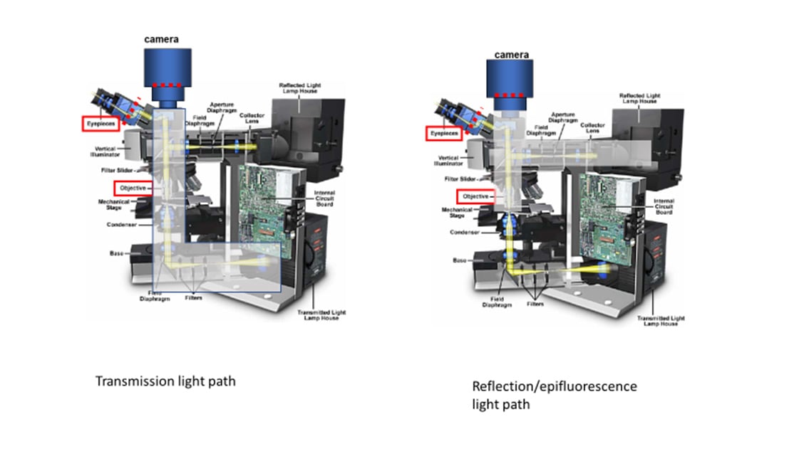
Fluorescence microscopy uses reflection or epi-fluorescence geometry, where the objective serves as both the illumination condenser and the imaging lens. The illumination light is passed through the objective and the detected light is passed backward through the objective and split off to a camera or eyepiece. One benefit of this approach is that light that doesn't interact with the sample travels away from the detector, maximizing separation of illumination light from fluorescent emission. The transmission and epi-fluorescence light paths are illustrated in Figure 4.
The useful life of each of these sources varies between a few hundred hours for mercury arc lamps, to 1000-2000 hours for mercury/metal halide and halogen lamps.
Putting the illumination source close to the sample limits control of light intensity and illumination field of view. Köhler imaged the light source to a focal length from the condenser lens, as illustrated in Fig.5. This provides control of the field of illumination, with a field stop in the middle of the imaging component and an aperture stop 1f away from the condenser. The aperture stop is a highly significant aspect of the design; allowing easy control of the light power to the sample. These stops usually have levers allowing the user to manually adjust the illumination area (field stop) and power (aperture stop) being delivered to the sample.
For example, one might wish to photograph a waterfall at a slow shutter speed to create a deliberate motion-blur effect. The photographer might determine that to obtain the desired effect, a shutter speed of ten seconds was needed. On a very bright day, there might be so much light that even at minimal film speed and a minimal aperture, the ten-second shutter speed would let in too much light, and the photo would be overexposed. In this situation, applying an appropriate neutral-density filter is the equivalent of stopping down one or more additional stops, allowing the slower shutter speed and the desired motion-blur effect.
Figure 2: Convex vs concave lenses. A convex lens is thicker at the center than the edge and will focus a beam of light to a point a certain distance in front of the lens (the focal length). A concave lens is the opposite, being thicker at the edge than the center and spreading out a beam of light. Microscopes use convex lenses in order to focus light. Image from http://clubsciencekrl.blogspot.com/.
Microscope partsand functions pdf
Another type of ND filter configuration is the ND-filter wheel. It consists of two perforated glass disks that have progressively denser coating applied around the perforation on the face of each disk. When the two disks are counter-rotated in front of each other, they gradually and evenly go from 100% transmission to 0% transmission. These are used on catadioptric telescopes mentioned above and in any system that is required to work at 100% of its aperture (usually because the system is required to work at its maximal angular resolution).
3It is suitable for linearly polarized light incident along the optical axis of the crystal. At this time, the polarization state of the light does not ...
In photography, ND filters are quantified by their optical density or equivalently their f-stop reduction. In microscopy, the transmittance value is sometimes used. In astronomy, the fractional transmittance is sometimes used (eclipses).
To address this issue, some manufacturers have developed variable ND filters. These filters consist of two polarizing filters, with at least one being rotatable. The rear filter blocks light in one plane, while the front filter can be adjusted. As the front filter rotates, it cuts down the amount of light reaching the camera sensor, allowing for nearly infinite control over light levels.
Two illumination methods, critical or Köhler, are commonly used to illuminate the sample in microscopy. The primary difference is whether they copy the structure (critical) or scramble the structure (Köhler) of the illumination source at the sample. As Köhler illumination is more frequently used, it will be covered in this article.
Conversely, the ocular lens, also known as the eyepiece, is situated near the observer's eye. Its primary function is to further magnify the image produced by ...
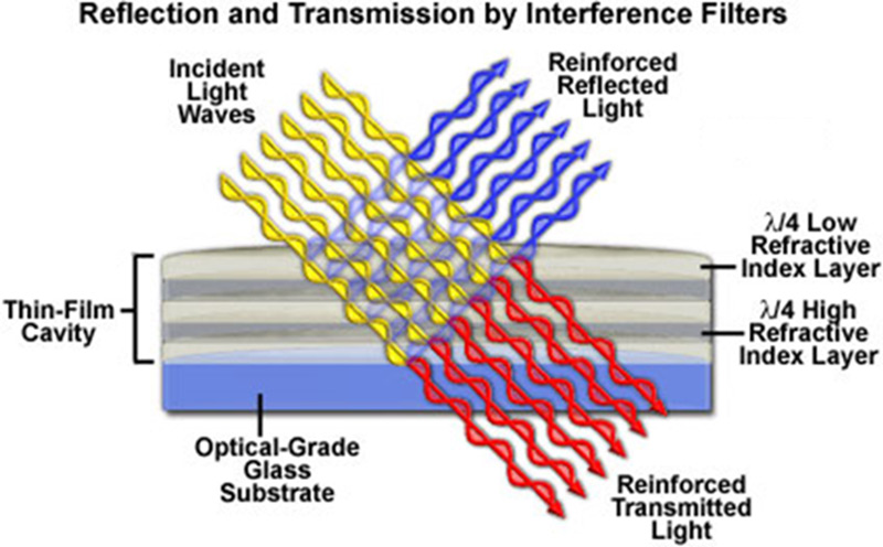
Filters are optical components that can transmit certain wavelengths of light while reflecting others. Color selection is critical for fluorescence imaging. An example of optical filtering is shown in Fig.7.
Figure 7: Modern color-selecting interference filter. The various layers on top of the glass substrate acting in total reflect blue light while allowing transmission of the red light. Taken from http://zeiss-campus.magnet.fsu.edu/articles/lightsources/leds.html
Köhler invented a focusable illumination system that allowed control of the field size, the power and the angle of illumination while scrambling the structure of the light source projected on the sample. He took advantage of the property of a lens to convert the lateral structure into parallel rays to do this. Putting an illumination source at the focal point of the lens transforms the output into uniform light rays on the other side, scrambling any structure inherent in the source. Multiple points emitting from the light source all end up scrambled and traveling in parallel rays after exiting the lens
In practice, ND filters are not perfect, as they do not reduce the intensity of all wavelengths equally. This can sometimes create color casts in recorded images, particularly with inexpensive filters. More significantly, most ND filters are only specified over the visible region of the spectrum and do not proportionally block all wavelengths of ultraviolet or infrared radiation. This can be dangerous if using ND filters to view sources (such as the Sun or white-hot metal or glass), which emit intense invisible radiation, since the eye may be damaged even though the source does not look bright when viewed through the filter. Special filters must be used if such sources are to be safely viewed.
6. Spring, K.R., Parry-Hill, M., Burdett, C.A., Sutton, R. T., Fellers, T.J. and Davidson, M.W. Laser Fundamentals in the Olympus Microscopy Primer website (https://www.olympus-lifescience.com/en/microscope-resource/primer/lightandcolor/laserhome/)
Microscope Partsdiagram
Figure 4: Transmission/trans-fluorescence and reflection/epi-fluorescence microscopy light paths in a model microscope. The gray area indicates the light paths involved for each mode. Derived from an image of a microscope on the Olympus Microscopy Primer and modified by the author.
ND filters find applications in several high-precision laser experiments because the power of a laser cannot be adjusted without changing other properties of the laser light (e.g. collimation of the beam). Moreover, most lasers have a minimal power setting at which they can be operated. To achieve the desired light attenuation, one or more neutral-density filters can be placed in the path of the beam.
A lens is an optical device that can refract light. The refraction depends on the shape of a lens, which is typically convex or concave. For the purposes of microscopy, convex lenses are used for their ability to focus light at a single point. This is how the human eye works, with the convex biological lens focusing light on the back of your eye where rod and cone cells can detect it. Microscopes borrowed this idea, using convex lenses to focus light towards a point that is f distance away from the lens. This distance is known as the focal length of the lens and depends on the shape. Lens shapes can be seen in Fig.2. It should be noted that these lenses are symmetrical and will have the same effect on light from either direction.
4. Reichman, J. 2017 Handbook of Optical Filters for Fluorescence Microscopy. Chroma Technology Company Bellows Falls, Vermont 05101-3119 (https://www.chroma.com/sites/default/files/HandbookofOpticalFilters.pdf)
An inexpensive, homemade alternative to professional ND filters can be made from a piece of welder's glass. Depending on the rating of the welder's glass, this can have the effect of a 10-stop filter.
Filters are commonly referred by the nature of their transmission, and the wavelength where they switch from transmission to reflection, as illustrated in Fig.8. A 500 nm short pass (SP) filter would transmit light bluer than 500 nm and reflect light redder than 500 nm. In contrast, a 500 nm long-pass (LP) filter will transmit light longer than 500 nm, reflecting light of shorter wavelengths.
A graduated ND filter is similar, except that the intensity varies across the surface of the filter. This is useful when one region of the image is bright and the rest is not, as in a picture of a sunset.
Apr 29, 2022 — ... New Jersey, USA. The newly opened Edmund Optics office in Cherry Hill, New Jersey. (Image: Edmund Optics). The building is less than three ...
Microscope partsand functions
At its core, a typical microscope is essentially a box designed to hold two lenses in precise positions so that light can be accurately magnified from the sample to the detector. The first of these two lenses is the objective lens, which is located close to the sample, moves when the focus dial is turned and has useful information such as magnification written on its side. The second is commonly referred to as the tube/collector lens, which is buried deep within the body of the microscope and rarely seen.
In photography and optics, a neutral-density filter, or ND filter, is a filter that reduces or modifies the intensity of all wavelengths, or colors, of light equally, giving no changes in hue of color rendition. It can be a colorless (clear) or grey filter, and is denoted by Wratten number 96. The purpose of a standard photographic neutral-density filter is to reduce the amount of light entering the lens. Doing so allows the photographer to select combinations of aperture, exposure time and sensor sensitivity that would otherwise produce overexposed pictures. This is done to achieve effects such as a shallower depth of field or motion blur of a subject in a wider range of situations and atmospheric conditions.
Figure 3: On microscope objective lenses. A) An example of the location of lenses in an objective cross-section, making this a complex lens. B) Different Nikon Super Fluor objectives, ranging from 10x to 40x. The red boxes show the magnification / NA of the lens, with the air 40x having an NA of 0.90 and the oil-immersion 40x having an NA of 1.30, showing the effect of the imaging medium on the NA (the denser the better). C) How different NA affects the illumination of the sample, the higher the NA the greater the angle of light from the objective, and the greater the maximum resolution.
These components are responsible for the magnification, resolution, and field of view inherent in the microscope. In this article, the details of microscope components and anatomy are explained in relation to how they contribute to providing the best possible image. In order to see the arrangement of these components, see Fig.1.
In the fluorescence microscope, a combination of excitation BP filter, a LP dichroic filter and an emission BP filter are organized into a cube holder to provide high-intensity excitation light to the sample and efficiently isolate emission light before steering it off to the camera.


 Ms.Cici
 8618319014500