
Heat and cold treatment: Which is best? - hot cold
And then there are those very special cases wherein a simple beam is not enough, however well it may be shaped. In the brazing of hot-dip galvanized sheets, for example, processes with normal spots run so unsteadily that you have to reduce the process speed to keep the number of spatters reasonably manageable. The solution is an award-winning innovation from Laserline: beam splitting by multi-spot optics. These turn a classic round or wide beam into a main spot with two pre-spots that remove the galvanization in the seam area, thus calming the process.
Without optics, no laser system! What may irritate the layman would actually be self-evident to the expert. The expert knows that the output of a laser beam source in and of itself is not capable of initiating a process.
Got the projector, got the globe, got the lens. Unfortunately, when I ordered the VGA dock, I was quoted a 4-6 week delivery time. 🙁
The screen height is 24.3 degrees, which means the angle should actually be 12.15 degrees. Both the post and the mount are incorrect at the moment.
Not so good news regarding the lens unfortunately. With the built-in macro lens on I get a good picture but it’s merely wide angle and not proper fisheye, with the macro lens removed I can fill the whole globe, but the projection becomes extremely blurry (unless I move the projector at least 10-15cm away from the lens, which isn’t really an option). Am I missing something really obvious? I’ll try to get started on the uVGA stuff next week.
Nice. I’ve been considering powering mine off of a Beagleboard to make it standalone, but the VGA out board for those is pretty bad. With the HDMI ShowWX, it would work nicely though.
First of all thanks a lot for sharing this – I’ve been wanting to build a dynamic globe for a friend of mine for ages but given a lack of crafting skills and knowledge about optics I never even started doing proper research, so it’s great that you’re sharing all the stuff you’ve already found out!
A certain amount of blurryness can be expected. If you are filling the entire 8″ globe in width and height of the projected image, you’ll be at a minimum of around 20 pixels per inch on the surface. If you make it fill only the width, and leave empty areas on the globe, your minimum is around 40 pixels per inch. Can you take a picture of what you’re seeing?
Pi shaper
It all looks really cool so far, but I’ve generated some interest with friends who design and build exhibits for the local science museum and I’d like to make this as professional-looking as possible.
Beamexpander
If you could incorporate realtime cloud maps or satellite weather, that would multiply the awesome factor by 15x at least.

Adjective · (optics) Free from color; transmitting light without color-related distortion. · Containing components such as achromatic lenses and prisms, ...
Actually calibrating a projector with slight pincushion through a $25 lens into a bathroom fixture attached together with some guesswork and a 3D printer is well beyond my linear algebra skill, so I simplified the calibration procedure down to four terms. We need to find the radius in pixels of the circle being projected and the x and y position of the center of that circle for starters. The more difficult part, which tested my extremely rusty memory of trigonometry is figuring out how to map the hemisphere coming out of the fisheye lens to the spherical display surface. For that, we have a single number for the distance from the center of the sphere to the lens, in terms of a ratio of the projected radius. The math is all available in the code, but the calibration script I wrote is pretty simple to use. It uses pygame to project longitude lines and latitude color sections as in the image above. You use the arrow keys to line up the longitude lines correctly to arrive at the x and y position, plus and minus keys to adjust the radius size until it fits the full visible area of the sphere, and 9 and 0 to adjust the lens offset until the latitudes look properly aligned. What you end up with is close enough to correct to look good, though as you can see in the images, the projector doesn’t quite fit the lens or fill the sphere. The script saves the calibration information in a pickle file for use elsewhere.
Standard ND filters are professional quality resin ND filters available between 1-4 stops of ND. Standard NDs don't block infrared, but they only go up to 4 ...
I got so engaged in this material that I couldn’t wait to read. It is truly a well-researched content and excellent wording. I am impressed with your work and skill. Thanks. Human Resources Software
Sure, you should have no issue beyond distortion when using a laser projector. If you use a conventional projector, the different depths will be out of focus.

Laser beamhomogenizer
If the composite video-out from a raspberry pi computer could work, that plus your code and a sub-$150 projector could make a real opportunity…
Bought a Ceylon Sapphire from Bismillah Gems, and the quality of the stone is fantastic. The customer service was exceptional—they took the time to explain everything about the stone, including its origin and benefits. I’m very happy with my purchase.
Gaussianbeam
That does look rather blurry. What are your calibration parameters? Radius, most importantly. You can figure out what your expected pixels per inch should be. It is possible though that the lens is just not very good in its fisheye configuration.
Cladding with lasers, also called laser metal deposition, has already a long tradition. And today, the meaning of the application has continued to…
See the difference through the polarized lens proves that the sunglasses are polarized. Unique paper material to check polarized sunglasses.
I found some good reviews for the lens, and the non-macro mode is actually the normal one. So no idea, if focus shouldn’t be a problem is it maybe something with the magnification that makes it require a minimum distance from projector to lens? It might generally be better to go for a Bloggie plug-and-play type lens rather than one for cameras with proper objectives.
I’m a bit lost regarding the lens though since the one you used is somewhat difficult to get here and I have absolutely no clue about optics, but would this be an appropriate substitute? http://opteka.com/43x.aspx Does the magnification make any difference regarding the projection?
Copper is one of the most important raw materials for electrical signal transmission and thus a key component of many modern technologies.
Thorlabs offers molded aspheres that are fabricated from either plastic or glass. They are available with or without anti-reflection (AR) coatings.
I’m glad you brought it up. The SHOWWX projects at an angle relative to its base such that the bottom of the projected image is on the same plane as whatever the projector is sitting on. So, the mount needs to be angled upwards at half the angular screen height.
I figured that I’d have to build libsdl-gfx from source. I’ll check ubuntu-restricted-extras. Thanks for that tip. Good to know that osgsnowglobe isn’t a viable thing to build. I got stuck building osgearth 2.1 (31 Aug 2011) from sources on my machine and I can’t connect to the recommended repository for the pre-built osgearth binaries so I’ll just shelve that effort for now.
▾. Wörterbuch Englisch-Deutsch · coed adj — · coed n — · cosBE konj [Abk.] — · cod n (Zoologie)— · cod sb.BE v — · cone n —.
I grabbed the air_traffic_2048.mp4 from sos.noaa.gov but it wouldn’t play on vlc (“no suitable decoder module for fourdd ‘mp4v'”) but I was able to re-render the file through ffmpeg, and that seems to run. I’m still working out how to make osgsnowglobe – I have no experience with cmake).
Looks like with the woot! deal on the SHOWWX, I’m going to bring the build cost in just over $180 not including whatever I do about a mount (I’m currently contemplating recycling an Ikea lamp base that was on the freebie pile at our Hackerspace).
Your python code could be some 20 times faster if you used numpy methods for computing the maths. You can avoid using loops, for example, to multiply each element of an array by ‘pi’, just do my_array * numpy.pi (as long as type(my_array) is )
that’s still realty impressive, im thinking of starting this project using ur diagram and the one from the microsoft site, to see what i can get.
In commercially available diode laser systems, beam shaping takes place via an optical system consisting of lens and mirror elements — the so-called processing optics. As the name suggests, these optics shape the laser beam in such a way that it is suitable for the planned material processing. In other words, it turns what the beam source spits out into a beam with which the user can actually do something. Two points are crucial here. First, it is important that the beam is suitable for welding, brazing, hardening or coating. Second, it must match the nature of the workpiece.
As far as I’m aware, the SHOWWX is the only consumer laser projector available, so you would have to go for a LCD or DLP projector. This introduces the problem of keeping the entire sphere in focus. Laser projectors are in focus at any distance, but you would need to focal plane of a normal projector to align to the surface of the sphere. This means you couldn’t use a fisheye lens to spread the light, but instead something like a silvered hemisphere centered in the globe.
Has anyone else _made_ the printed mount? Did anyone else have to tweak the STL to get satisfactory results? I’m just starting to play with calibration and such, but as built, the axis of the projected globe image is nearly an inch off the top of the center point of the glass globe.
sudo apt-get install libsdl-dev sudo apt-get install cmake sudo apt-get install libsdl-image1.2-dev sudo apt-get install libvlc-dev sudo apt-get install libsdl-net1.2-dev sudo apt-get install libsdl-gfx1.2-dev sudo apt-get install libsdl-ttf2.0-dev sudo apt-get install libsdl-mixer1.2-dev sudo apt-get install vlc-nox (needed or you get an error about libraries)
Beamshaper
OK… I have the ShowWX on order, I’ve snarfed the SnowGlobe code from GitHub, and I’m evaluating fisheye lenses. I have a Makerbot Cupcake for a 3D printer at the moment, though I’m building a Mendel. It looks like the mounting bracket needs the bed size of a Mendel. It also looks like your horizontal bolt holes are a cylinder, not the classic RepRap teardrop. Any problems with filaments collapsing into your bolt holes?
The heat treatment of metal, such as the hardening of steel, is one of the oldest industrial processes. Its roots go back to antiquity. Even today's…
For $50 the SHOWWX+ you could get Optoma Pico PK301 Projector at 50 lumens it is 35 lumens brighter than the SHOWWX+ it has digital input hdmi check out http://goo.gl/ynkSI
Here’s what the actual globe looks like: http://sukzessiv.net/~kevin/globe.png I changed the colors of the calibration script to black and white because I couldn’t properly make out the boundaries in the original red-pink blur. It’s not just the camera failing to get the globe into focus, it does really look like that.
Not only does size matter, but so does geometry. The question arises whether the spot should be rectangular, round or linear, a choice whose significance will become apparent during coating. Here, rectangular wide beams are often used across the board because they promise effective machining with high coating rates. However, a rude awakening regularly occurs when components are filigree and sharp-tapered, as in the case of machine knives. In this case, the wide beam often delivers so much energy to the component that the self-quenching no longer works and, in the worst case scenario, the cutting edges melts off. Those who rely on narrow, focused round spots here and only hit the stronger surfaces with the wide beam have a clear advantage. In addition, it should be possible to switch flexibly between the two spot shapes. High-quality optics such as those from Laserline make this possible.
I still only have a CupCake for 3D printing, but I just got a MendelMax owner to print me the full-sized globe mount. I grabbed the OpenSCAD file off of GitHub and figured out that the grooves for the lens mount (in the opteka() module) do *not* match the profile of the Opteka fisheye lens I have. I measured my lens base and tweaked opteka() and with a little bit of filing to remove a few blobs, now have an assembled globe/projector stand.
Sorry, had an internet outage for a couple of days. My globe is actually 11″, so I might head back to the store to get a smaller one too. I don’t think it’s just the resolution though, here’s the ShowWX default screen projected against a flat wall through the Opteka .43x, with the macro lens attached (left) and removed (right): http://sukzessiv.net/~kevin/lens.png The lens wasn’t properly centred on the second one but you get the idea. Projection was from really close up too.
Here is a classic example. A beam meant to be used for hardening applications must be particularly homogeneous. The optics must therefore ensure that the energy distribution is as uniform as possible. Special homogenizing optics are available for this purpose, which further optimize the inherently homogeneous diode laser beam. In addition, the beam must be suitably dimensioned as well. For example, if a cam is to be hardened, the spot should not be wider than the cam itself, otherwise it would literally miss the mark. Optics take care of that, too. They adjust the spot size and, if in doubt, even do so while the process is running. Laserline offers motorized zoom optics that can change the spot during the machining process, thereby always ensuring the perfect size.
I bought a turquoise stone from Bismillah Gems and was pleasantly surprised by the quality. The turquoise stone price was reasonable, and the staff explained all the benefits clearly. A great place for gemstones!
I would like to replicate this project myself, but the Opteka Fisheye Lens you used is “currently discontinued”. Other than the importance of ensuring that the lens has a large enough opening (e.g. >30mm) and is 180 degrees, are there any other factors that need to be taken into account?
Flat-topbeam
KM05T/M - SM05-Threaded Kinematic Mount for Thin Ø12.7 mm Optics, M4 Taps.
... Glass ZB2 BG3 For Photography at Aliexpress for . ... square 7.0/ 5.5 Watch glass lens sapphire single date window crystal convex transparent magnifying glass ...
P.S. here’s another 20 lumen laser projector I came across (somewhat pricier, but for those who need the extra brightness): http://www.aaxatech.com/products/l1_laser_pico_projector.htm
OK… got libsdl-gfx2.0 built and installed (and ‘predict’ installed and running locally) and I’m looking at an sosg window with live satellite data and historical tracks. Very cool.
Because I didn’t see “libsdl-gfx2.0-dev” in the ordinary repositories, I grabbed v1.2. That version appears not to support thickLineColor() so I commented that one line out and at least got ‘sosg’ to compile.
The application fields of diode lasers are are broad and diverse – but there are certain key areas. One of them is the process of metal welding.
I think this is absolutely brilliant and I can’t wait to see how it goes for you. I may borrow your idea for an idea I had for constellations.
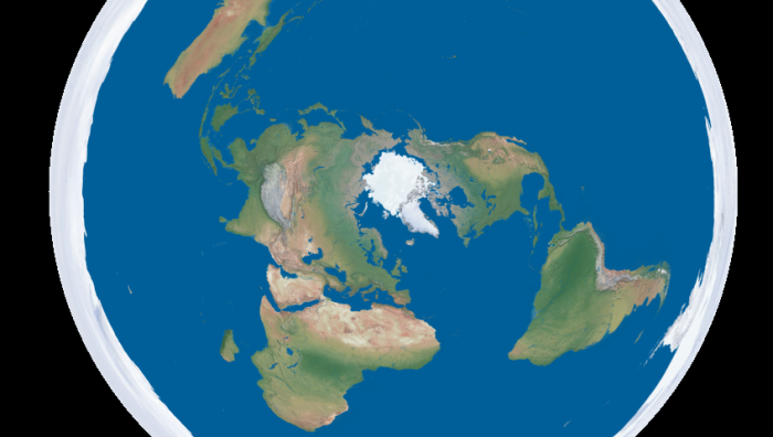
Going back to the initial goal, I wrote a script to turn equirectangular projected maps of the Earth into roughly azimuthal equidistant projected images calibrated for a Snow Globe like the one above. There are plenty of maps of the former projection available freely, like Natural Earth and Blue Marble. Written in python, the script is quite slow, but it serves as a proof of concept. The script, along with the calibration script and the models for the 3D printed mounts are all available on github. I’ve finally fully accepted git and no longer see a point in attaching the files to these posts themselves. I put a Part One in the title to warn you that this blog is going to be all Snow Globe all the time for the foreseeable future. Up next is writing a faster interface to interactively display to it in real time, and if I think of a good way to do it, touch input is coming after that.
My ShowWX arrived last week, and since I’m trying to build a portable ‘standalone’ version I’ve also ordered this: http://www.4dsystems.com.au/prod.php?id=149 The chip can still handle the ShowWX’s 848×480 and with the onboard SD reader I should be able to cycle through different maps stored on the SD card as well as do some simple manipulations (e.g. rotation). Truely dynamic maps will be difficult, although you can do some simple painting with the chip and it is in principle capable of displaying videos too.
The projector you mention advertises that it can project up to 100 inches. Do you think this type of setup would work with an 8 foot sphere? I’m trying to launch a weather balloon with a spherical projection. best steve
Thank you so much for sharing your thoughts. Your work is enjoyable and the presentation is quite effective. It’s a valuable and practical read for us. Thank you. Attendance Software
Thanks for sharing your project, it’s much appreciated. I am working on an interactive sphere and I’ve purchased a 180 degree fisheye lens to mount on my projector. However, it’s not a pico projector as the lumens is way too low as I plan to make a rather large sphere. I am having trouble with the focus, everything seems to be very blurry. Could you share any insight as to how to fix this problem?
Since reading Snow Crash, I’ve been drawn to the idea of having my own personal Earth. Because I’m stuck in reality and the virtual version of it is always 5 years away, I’m building a physical artifact that approximates the idea: an interactive spherical display. This is of course something that exists and can likely be found at your local science center. The ones they use are typically 30-100″ in diameter and cost enough that they don’t have prices publicly listed. Snow Globe is my 8″ diameter version that costs around $200 to build if you didn’t buy a Microvision SHOWWX for $600 when they launched like I did.
I took the VGA dock apart to remove the bottom plate of it. The printed part fits in the area where the bottom plate normally is.
The parameters used for the two pictures above were 334 radius and 181 offset, does that make any sense? I think Africa is extending way too far down on the picture which probably means that the lower hemisphere isn’t properly proportioned at all. I also had another setting with 486 and 486 that looked reasonable.
Thats pretty awesome. We have one of the 72 in. omniglobes from arcscience, and the end cost for that was nearly $250,000.
How to design a Gaussian to top hatbeamshaper
... shipping, wholesales, or OEM. - Buy Testing Card for Polarized Sunglasses Polarization Test Polaroid Lens Polarise Examining.
I can’t wait to see more of it ! (something like http://www.geophysique.be/2011/02/19/matplotlib-basemap-tutorial-08-shooting-great-circles/) !!!
At 100 inches, it is extremely dim even in pitch black. 8 inch diameter is usable, 12 would probably be the limit even with the SHOWWX+. 8′ would need a much more powerful projector.
I only stumbled upon this today, so I might be two and a half years late to the party when I ask this, but what factors need to be taken into account when purchasing a Fisheye Lens for this project?
I’ve had a lot of fun recently copying keys and people, but my objective in building a 3D printer was to make it easier to do projects like this one. Designing a model in OpenSCAD, printing it, tweaking it, and repeating as necessary is much simpler than any other fabrication technique I’m capable of. In this case, I printed a mount that attaches the lens to the correct spot in front of the projector at a 12.15° angle to center the projected image. I also printed brackets to attach the globe to the lens/projector mount. The whole thing is sitting on a GorillaPod until I get around to building something more permanent.
Laguerre Gaussbeam
I’m curious to learn more about creating a snow globe effect through DIY spherical projection. Excited to dive into this project and bring a touch of winter wonder to my home décor!
Good question, I haven’t actually found really satisfying calibration settings. Whenever the upper half is properly aligned and proportioned, the lowest 45° (which should at least show up as a white rim in my case) are nowhere to be seen, which means there’s a lot of guesswork involved. Doing the +/- stuff first and only then changing the offset isn’t really doing it either.
Sharp GH04850B2G 488nm 55mW Blue Laser Diode 5.6mm Package - Sharp GH04850B2G 488nm 55mW Blue Laser Diode 5.6mm Package [Specification] Product Name: Laser ...
The basic design here is to shoot a picoprojector through a 180° fisheye lens into a frosted glass globe. The projector is a SHOWWX since I already have one, but it likely works better than any of the non-laser alternatives since you avoid having to deal with keeping the surface of the sphere focused. Microvision also publishes some useful specs, and if you ask nicely, they’ll email you a .STL model of their projector. The lens is an Opteka fisheye designed to be attached to handheld camcorders. It is by far the cheapest 180° lens I could find with a large enough opening to project through. The globe, as in my last dome based project is for use on lighting fixtures. This time I bought one from the local hardware store for $6 instead of taking the one in my bathroom.
Is there a specific magnification (e.g. 0.2x), type of fisheye lens (circular or full-frame), and mapping function (Stereographic, Equidistant, Equisolid angle, or Orthographic) required?
With that, I seemed to have run into another situation… it looks to me as if the projector mount was designed to center the image when the ShowWX is mounted bare, not in its VGA dock. I can get a good image by sliding the lens down the mount groove away from center, but the edges of the projected image are cloudy (from misalignment) if I try to center the lens. I think I also had to remove the rubber feet from the VGA dock or the image was _really_ misaligned with the lens.
The teardrop isn’t really necessary anymore, for that sized hole at least. You may get a strand that falls into the hole, but nothing that effects functionality.
This is awesome. Wish someone sold them commercially. Also wish there was a version conforming to a cube. Keep up the great work.
You end up with a slightly off-center projection. The calibration script corrects for that, but the gap outside of the projection area will be larger on one side than the other.
The list of examples is of course somewhat long. But it should already be clear to anyone by now why we said what we said at the beginning: without optics, no laser system! It simply cannot be done without them, because the world of applications is much too complex. And wouldn’t it be a shame not to take advantage of the possibilities? Sure, in purely theoretical terms, you might as well just fix the fiber in the area near a workpiece, turn the knob on the beam source a bit, and something would happen. But as the ancients said: "Quidquid agis, prudenter agas et respice finem" (= whatever you do, do it wisely and consider the end result).
For a lens, you’re mostly just looking for something that does a 180 degree fisheye. Something that follows the first projection formula on this page: http://wiki.panotools.org/Fisheye_Projection
Top Laser Components Selection | Order easily now: Laser Components Laser diode Red 660 nm 50 mW ADL -66505 TL | Fast delivery | Reasonable prices.
Awesome project Nirav:) I’m trying to cobble together another cheap version using this projector + fisheye lens combo from these Chinese dudes on ebay: http://www.ebay.com/itm/Mini-Portable-Multimedia-Pocket-Cinema-Pico-Projector-iPod-iPhone-Tripod-/320765917980 http://www.ebay.com/itm/180-Degree-Wide-Angle-FishEye-Lens-for-Phones-and-cameras-Detachable-/150665785877
Thanks for the tip! Just ordered one – by the time I get the frame printed and locate a lens and such, the new version will probably be on clearance, but for now, this is awesome!
Do you think ArcScience and PufferSphere are working around this patent somehow or licensing the technology from Global Imagination?
Hey! Did you figure this out? I’m trying to make a touch-sensing dome at maybe 4 ft in diameter.The best I could come up with is to use the projector with a kinect sensor, but I am not sure how the calibration would be affected, and if I could get the touches to line up at all with the dome.
What would be the resolution on this display? could u reproduce “http://research.microsoft.com/en-us/um/people/benko/projects/sphere/”?
Hi, good project. I would like to replicate orb kitt (http://play.kendincos.com/171368/Wlptxtxdhnrdhptlp-kitt-3-0-voice-orb-animation-with-dashconsole.html) The diameter of the sphere is approximately 10 cm (4″). With that lens and the projector, the image takes up at least half a sphere? (sorry for my english) thanks to all
You’ll also run into the issue of focusing the image on the surface of the sphere. The distance from the projector to the surface of the sphere varies from a few centimeters to the diameter of the sphere. Using a laser projector lets you avoid the issue.
The question seems a bit old-fashioned now. Indeed, haven’t we known the answer for ages? At the very least, it’s not like this technology just came…
What the source emits is concentrated energy, but it needs to be put on the right track. The magic word here is beam shaping, and nothing works without optics. Diode lasers are no exception. They cannot be released onto a workpiece without optics, even if they are fiber-coupled. The fiber guides the beam to the workpiece, but does not usually shape it unless special fiber optics are used. However, that would be a wholly different topic.
It will take me a while to construct the ring and mount (we have Cupcakes galore near me, but no Mendels yet), so perhaps real-time stuff will emerge about the time I have a working display.


 Ms.Cici
 8618319014500