
Free-Space Optical Communication Technologies for Next ... - free-space optical
MTFcamera
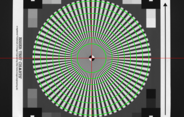
Figure 2 : Siemens star with concentric circles (shown in green), with their centers coincides with the centroid of the testchart (red cross).
MTFimage sensor
This entry was posted on Thursday, February 20th, 2014 at 3:09 pm and is filed under Uncategorized. You can follow any responses to this entry through the RSS 2.0 feed. You can leave a response, or trackback from your own site.
In principle, these two steps is all one needs to be able to measure/calculate the MTF. But to obtain a higher accuracy of the measurements, the following additional steps might be required :
The MTF is not really the most easiest measurement that can be done on an imaging system. Various methods can be used to characterize the MTF, such as the “slit image”, the “knife edge”, the “laser-speckle technique” and “imaging of sine-wave patterns”. It should be noted that all method listed, except the “laser-speckle technique, measure the MTF of the complete imaging system : all parts of the imaging system are included, such as lens, filters (if any present), cover glass and image sensor. Even the effect of the processing of the sensor’s signal can have an influence on the MTF, and will be include in the measurement.
Modulation transfer function image processing
As indicated in Figure 3, the MTF measurement is done with white light created by 3 colour LED arrays (wavelengths 470 nm, 525 nm, 630 nm). As can be seen from the curve, the camera has a relative low MTF, around 8 % at Nyquist frequency (fN). In theory an imager with a large fill factor can have an MTF value of 60 % at fN. But this camera is performing far away from this theoretical value. But one should not forget, this MTF measurement does include ALL components in the imaging system, not just the sensor !
MTFOptics
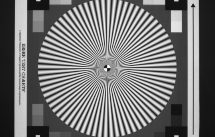
The method described here is based on the work of Anke Neumann, written down in her MSc thesis “Verfahren zur Aufloesungsmessung digitaler Kameras”, June 2003. The basic idea is to use a single testchart with a co-called Siemens-star. An example of such a testchart is illustrated in Figure 1.
IN the variable width method of recording sound on film, a galvanometer is used in which a loop of metal ribbon, 0-005 in. broad and 0-0005 in. thick, is placed between the poles of a permanent magnet, a small mirror being cemented across the two arms of the loop. When speech currents from the microphone and amplifiers pass along the ribbon, the mirror vibrates and causes the reflected beam of light to traverse a narrow slit at right angles to the direction of motion of the film, and thus trace a graph of the sound waves. Since the upper limit of reproduction from the ordinary talking film projection apparatus is about 6000 cycles-per second, the natural frequency of oscillation of the galvanometer must be at least as great as this. The inertia of its moving parts must, therefore, be low. The mirror must be as light and small as possible. It should also be accurately surfaced and silvered in order to ensure uniform reflection. The production of such mirrors is an interesting piece of optical work involving manipulative processes on a different scale from that employed for the usual products of the manufacturing optician. Mirrors made by Messrs. Taylor, Taylor and Hobson, Ltd., Stoughton Street Works, Leicester, specially suitable for these galvanometers, are rectangular in shape and measure 0-032 in. by 0-018 in. by 0-004 in. The glass from which they are made is first cut to the correct size and then optically worked on both sides. The back surface is silvered by cathode sputtering and is protected by a suitable varnish. The finished mirror weighs 0-0001 gm.
Hi Per, These subjects will be discussed, but when ? Time needed to perform the measurements is a problem at this moment, too busy with other projects. And recently I was facing some nasty issues with the hardware I am using …. Albert.
Modulation transfer function Radiology ppt
MTFimage quality
Hi Did you do the image processing and MTF analysis directly for the RAw image or did you first convert it into an RGB image?
Thanks for the very informative article. What would be a typical MTF of the lens or the lens system? Does this sensor use microlenses?
In this first MTF-blog the measurement of the modulation transfer function based on imaging with a sine-wave pattern will be discussed. It should be noted that in this case dedicated testcharts are used to measure the MTF, but the pattern on the chart should sinusoidally change between dark parts and light parts. In the case a square-wave pattern is used, not the MTF but the CTF (= Contrast Transfer Function) will be measured. And the values obtained for the CTF will be larger than the ones obtained for the MTF.
MTFlens
Hi, Thank you for a very good blog. Also wondering if you will look at the MTF of a pixel and how the Bayer pattern affects the sampling? Since color channels are not completely separated from each other.
(Without going further into detail, the testchart contains more structures than used in the reported measurement performed for the MTF.) The heart of the testchart is the Siemens star with 72 “spokes”. As can be seen the distance between the black and white structures on the chart is becoming larger if one moves away from the center of the chart. In other words, the spatial frequency of the sinusoidal pattern is becoming lower at the outside of the Siemens star, and is becoming higher closer to the center of the Siemens star. Around the center of the Siemens star, the spatial frequency of the sinusoidal pattern is even too high to be resolved by the camera-under-test and aliasing shows up. In the center of the Siemens star a small circle is included with 2 white and two black quarters. These are going to play a very important role in the measurements.
Thank you for visiting nature.com. You are using a browser version with limited support for CSS. To obtain the best experience, we recommend you use a more up to date browser (or turn off compatibility mode in Internet Explorer). In the meantime, to ensure continued support, we are displaying the site without styles and JavaScript.
In a simple wording, the modulation transfer function or MTF is a measure of the spatial resolution of an imaging component. The latter can be an image sensor, a lens, a mirror or the complete camera. In technical terms, the MTF is the magnitude of the optical transfer function, being the Fourier transform of the response to a point illumination.
2) You say that the pixel values around the green circle change according to a sine wave. I would have thought that it is the case if the resolution of the system under test is low but when it is high it would look more like a square wave from black (0) to white (1) but with rounded corner. I am correct?


 Ms.Cici
 8618319014500