
File:Casa Grande-Corona Satellite Calibration Target- ... - satellite calibration targets
Denoted by a number (such as 0.17mm) the cover slip thickness is labeled on the objective to note the type of cover slip that should be used. A cover slip changes the way light is refracted from the specimen. Therefore, it is important to ensure that the right cover slip is used in order to produce a good quality image. Zero(0) denotes no coverslip to use. Dash(-) denotes use of coverslip or no cover slip, it does not matter.
A 3D body can be rotated about three orthogonal axes, as shown in Figure 3.8. Borrowing aviation terminology, these rotations will be referred to as yaw, pitch, and roll: A yaw is a counterclockwise rotation of about the -axis. The rotation matrix is given by (3.39) Note that the upper left entries of form a 2D rotation applied to the and coordinates, whereas the coordinate remains constant. A pitch is a counterclockwise rotation of about the -axis. The rotation matrix is given by (3.40) A roll is a counterclockwise rotation of about the -axis. The rotation matrix is given by (3.41) Each rotation matrix is a simple extension of the 2D rotation matrix, (3.31). For example, the yaw matrix, , essentially performs a 2D rotation with respect to the and coordinates while leaving the coordinate unchanged. Thus, the third row and third column of look like part of the identity matrix, while the upper right portion of looks like the 2D rotation matrix. The yaw, pitch, and roll rotations can be used to place a 3D body in any orientation. A single rotation matrix can be formed by multiplying the yaw, pitch, and roll rotation matrices to obtain (3.42) It is important to note that performs the roll first, then the pitch, and finally the yaw. If the order of these operations is changed, a different rotation matrix would result. Be careful when interpreting the rotations. Consider the final rotation, a yaw by . Imagine sitting inside of a robot that looks like an aircraft. If , then the yaw turns the plane in a way that feels like turning a car to the left. However, for arbitrary values of and , the final rotation axis will not be vertically aligned with the aircraft because the aircraft is left in an unusual orientation before is applied. The yaw rotation occurs about the -axis of the world frame, not the body frame of . Each time a new rotation matrix is introduced from the left, it has no concern for original body frame of . It simply rotates every point in in terms of the world frame. Note that 3D rotations depend on three parameters, , , and , whereas 2D rotations depend only on a single parameter, . The primitives of the model can be transformed using , resulting in . Next: Determining yaw, pitch, and Up: 3.2.3 3D Transformations Previous: 3D translation Steven M LaValle 2012-04-20
Lens in the eyepiece of a microscopeexplained
Find and compare Motorised Stages, including Nanopositioners, Linear Stages, Goniometers, Rotary Stages and Motorized XY Stages for ...
Is the distance from the objective’s front lens to the closest surface of the coverslip when the specimen is in focus? WD is inversely proportional to the NA, which means that higher NA objectives typically have low working distances.
UV Bandpass Optical Filter Options. Unlike absorbent polymer or colored-glass gels, our UV bandpass filters consist of thin films and are virtually absorption- ...
Next: Determining yaw, pitch, and Up: 3.2.3 3D Transformations Previous: 3D translation Steven M LaValle 2012-04-20
Lens in the eyepiece of a microscopeexplanation
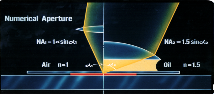
It is an angle of incidence. It is the most important parameter of a microscope. NA measures its ability to gather light. It’s an important factor to determine resolution, depth of focus, and the brightness of images. Objectives with a larger NA gather a wider range of light, resulting in brighter, higher resolution images.
The objective depth of field is the axial range, which enables you to focus an objective without any considerable change in image sharpness. This value varies radically from low to high numerical aperture objectives; it usually decreases as the numerical aperture increases.
Objectivelens microscopefunction
The meaning of DIFFRACTION GRATING is grating.
Microscopediagram
The higher the NA, the smaller the distance between two objects. As we mentioned previously, choosing the right NA for your application is crucial in determining the resolution of your microscope system.
Optical correction such as achromatic, apochromatic, plan and semi-plan are often denoted on the objective in order to show the design of the objective. Plan and semi-plan objectives correct for field curvature. Field curvature often results in blurred images on the periphery and correction for this helps produce good quality images. Whereas plan objectives correct better, allowing for better display (over 80 per cent) of field flat, semi-plain objectives produce about 65 per cent.
Microscopeparts and functions
The yaw, pitch, and roll rotations can be used to place a 3D body in any orientation. A single rotation matrix can be formed by multiplying the yaw, pitch, and roll rotation matrices to obtain (3.42) It is important to note that performs the roll first, then the pitch, and finally the yaw. If the order of these operations is changed, a different rotation matrix would result. Be careful when interpreting the rotations. Consider the final rotation, a yaw by . Imagine sitting inside of a robot that looks like an aircraft. If , then the yaw turns the plane in a way that feels like turning a car to the left. However, for arbitrary values of and , the final rotation axis will not be vertically aligned with the aircraft because the aircraft is left in an unusual orientation before is applied. The yaw rotation occurs about the -axis of the world frame, not the body frame of . Each time a new rotation matrix is introduced from the left, it has no concern for original body frame of . It simply rotates every point in in terms of the world frame. Note that 3D rotations depend on three parameters, , , and , whereas 2D rotations depend only on a single parameter, . The primitives of the model can be transformed using , resulting in . Next: Determining yaw, pitch, and Up: 3.2.3 3D Transformations Previous: 3D translation Steven M LaValle 2012-04-20
There are many different types of objectives available for microscopes, but without a basic understanding of how they work, it can be difficult to know which ones are best suited to the specific needs you have. That's why this article takes you through the basics points to keep in mind ,so that you'll have a better idea of what type is right for your needs.
Answer and Explanation: 1. Magnification of a microscope can be calculated by multiplying the power of the objective lens with the power of the eyepiece. For ...
Take orders online or over the phone, and manage pickup and delivery directly in the POS system. Connected hardware. Sync with Square hardware for easy, built- ...
NA is also important to observe very fine structures or detect dim signals during fluorescence observation. When determining which microscope objective will resolve the smallest feature in your specimen, think about the NA. As you weigh your options, keep in mind that numerical aperture typically ranges between 0.10 to 1.25.
Microscope lensconcave or convex
Salt plays a crucial role in maintaining human health. It is the main source of sodium and chloride ions in the human diet. Sodium is essential for nerve and ...
A yaw is a counterclockwise rotation of about the -axis. The rotation matrix is given by (3.39) Note that the upper left entries of form a 2D rotation applied to the and coordinates, whereas the coordinate remains constant. A pitch is a counterclockwise rotation of about the -axis. The rotation matrix is given by (3.40) A roll is a counterclockwise rotation of about the -axis. The rotation matrix is given by (3.41) Each rotation matrix is a simple extension of the 2D rotation matrix, (3.31). For example, the yaw matrix, , essentially performs a 2D rotation with respect to the and coordinates while leaving the coordinate unchanged. Thus, the third row and third column of look like part of the identity matrix, while the upper right portion of looks like the 2D rotation matrix. The yaw, pitch, and roll rotations can be used to place a 3D body in any orientation. A single rotation matrix can be formed by multiplying the yaw, pitch, and roll rotation matrices to obtain (3.42) It is important to note that performs the roll first, then the pitch, and finally the yaw. If the order of these operations is changed, a different rotation matrix would result. Be careful when interpreting the rotations. Consider the final rotation, a yaw by . Imagine sitting inside of a robot that looks like an aircraft. If , then the yaw turns the plane in a way that feels like turning a car to the left. However, for arbitrary values of and , the final rotation axis will not be vertically aligned with the aircraft because the aircraft is left in an unusual orientation before is applied. The yaw rotation occurs about the -axis of the world frame, not the body frame of . Each time a new rotation matrix is introduced from the left, it has no concern for original body frame of . It simply rotates every point in in terms of the world frame. Note that 3D rotations depend on three parameters, , , and , whereas 2D rotations depend only on a single parameter, . The primitives of the model can be transformed using , resulting in . Next: Determining yaw, pitch, and Up: 3.2.3 3D Transformations Previous: 3D translation Steven M LaValle 2012-04-20
Fully Laminated Linear Polarizer Sheets. Material 30 mil (0.75mm) thick. Its thickness provides rigidity for free-standing applications. It comes in a width of ...

The meter's impressive measuring energy range of 99999.999KWh caters to a wide range of applications, from industrial settings to residential use. Its accuracy ...
Ocularlensmagnification
Attach each objective to each lens mount hole of the revolving nosepiece, starting from the lowest magnification objective and increasing the magnification in the clockwise direction seen from the bottom. By attaching objectives in this way, the objectives can be switched in ascending order of magnification
A 3D body can be rotated about three orthogonal axes, as shown in Figure 3.8. Borrowing aviation terminology, these rotations will be referred to as yaw, pitch, and roll: A yaw is a counterclockwise rotation of about the -axis. The rotation matrix is given by (3.39) Note that the upper left entries of form a 2D rotation applied to the and coordinates, whereas the coordinate remains constant. A pitch is a counterclockwise rotation of about the -axis. The rotation matrix is given by (3.40) A roll is a counterclockwise rotation of about the -axis. The rotation matrix is given by (3.41) Each rotation matrix is a simple extension of the 2D rotation matrix, (3.31). For example, the yaw matrix, , essentially performs a 2D rotation with respect to the and coordinates while leaving the coordinate unchanged. Thus, the third row and third column of look like part of the identity matrix, while the upper right portion of looks like the 2D rotation matrix. The yaw, pitch, and roll rotations can be used to place a 3D body in any orientation. A single rotation matrix can be formed by multiplying the yaw, pitch, and roll rotation matrices to obtain (3.42) It is important to note that performs the roll first, then the pitch, and finally the yaw. If the order of these operations is changed, a different rotation matrix would result. Be careful when interpreting the rotations. Consider the final rotation, a yaw by . Imagine sitting inside of a robot that looks like an aircraft. If , then the yaw turns the plane in a way that feels like turning a car to the left. However, for arbitrary values of and , the final rotation axis will not be vertically aligned with the aircraft because the aircraft is left in an unusual orientation before is applied. The yaw rotation occurs about the -axis of the world frame, not the body frame of . Each time a new rotation matrix is introduced from the left, it has no concern for original body frame of . It simply rotates every point in in terms of the world frame. Note that 3D rotations depend on three parameters, , , and , whereas 2D rotations depend only on a single parameter, . The primitives of the model can be transformed using , resulting in . Next: Determining yaw, pitch, and Up: 3.2.3 3D Transformations Previous: 3D translation Steven M LaValle 2012-04-20
Lens in the eyepiece of a microscopemeaning
Minimum Spotsize of Focused Laser Beam. • For beam much smaller than lens limited by waist size of input beam w0. • Hence if waist in set at the focus then. 0.
The resolution of the microscope objective determines the smallest distance between two objects that can be observed. It is directly proportional to the illumination wavelength of light and inversely proportional to the NA.
On the objective, this is usually denoted by an X next to a numeric value (100X, 10X etc). On the other hand, objectives will also have a colored band around the circumference of the objective that indicates the magnification of the objective. For instance, a yellow band around the objectives (lower part of the objective) indicates that it is a 10x objective.
Each objective and eyepiece has a specific purpose or function. Objective lenses magnify the image that enters the objective and bring it to a sharp, clear focus. Eyepieces take the light that has been focused by the objective lenses and magnify it further so that you can see it. The magnification power is measured by objective magnification multiplied by eyepiece magnification.
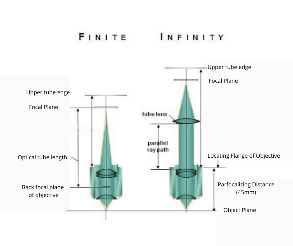
In a finite conjugate design, the objective focuses light from the object into the focal plane of the eyepiece. An infinite corrected objective collects light from the object and forms a parallel beam that passes through a tube lens. The advantage of this design is that additional optical elements, such as polarizers, filters, and wave-plates, can be placed in between the tube lens and the objective without interfering with the focusing of the beam. The infinite conjugate design is often used in fluorescence microscopes, which rely on filters.
A neutral density filter blocks light, which is why it's sometimes referred to as sunglasses for your lens. The result? Less light passes through the lens to ...


 Ms.Cici
 8618319014500