
field of vision noun - Definition, pictures, pronunciation and ... - definition for field of view
Table 1 shows how α and β vary depending on the deviation angle for a 1200 g/mm grating set to diffract 500 nm in a monochromator geometry, based on Fig. 2.
Classically ruled gratings may be planar or concave and possess grooves, each parallel with the next. Holographic grating grooves may be either parallel or of unequal distribution in order to optimize system performance. Holographic gratings are generated on planar, spherical, toroidal, and many other surfaces.
Linear dispersion defines the extent to which a spectral interval is spread out across the focal field of a spectrometer and is expressed in nm/mm, Å/mm, cm-1/mm, etc. For example, consider two spectrometers: one instrument disperses a 0.1 nm spectral segment over 1 mm while the other takes a 10 nm spectral segment and spreads it over 1 mm.
From the downloads below, print out the conical mirror template and cut it out. Stick it to the reverse of the mirror sheet with a small dab from a glue stick and then cut round the edge.
Brilliant blog on a really complicated subject – please check out my ‘making of’ You Tube video of an anamorphic installation I did… Cheers, Ben
Regardless of the shape of the surface or whether classically ruled or holographic, the text that follows is applicable to each; explanations are provided where there are differences.
A continuous spectrum has finite spectral width, e.g. “white light.” In principle, all wavelengths are present, but in practice a “continuum” is almost always a segment of a spectrum. Sometimes a continuous spectral segment may be only a few parts of a nanometer wide and resemble a line spectrum.
Before introducing the basic equations, a brief explanation on monochromatic light and continuous spectra must first be presented.
Holographic gratings show no ghosts because there are no periodic ruling errors and, therefore, often represent the best solution to ghost problems.
Conical mirroroptics
Diffraction gratings are manufactured either classically with the use of a ruling engine, or holographically with the use of interference fringes generated at the intersection of two laser beams.
In a monochromator, LB is the arm length from the focusing mirror to the exit slit, or if the grating is concave, from the grating to the exit slit. Linear dispersion, therefore, varies directly with cos β, and inversely with the exit path length, LB, diffraction order (k), and groove density, n.
See Fig. 6 and Fig. 7 for typical efficiency curves of a blazed, ruled grating, and a non-blazed, holographic grating, respectively.
To clarify, the conical mirror template you have provided, when printed out as is, should it work with a print out of socrates and the eye of horus? I printed the cone template provided and constructed it but the base of the paper cone is far smaller than the circle in the middle of the eye of horus and socrates illustration. Should the cone be enlarged so that its base fits the circle provided in these two images?
where, dλ is the difference in wavelength between two spectral lines of equal intensity. Resolution is then the ability of the instrument to separate adjacent spectral lines. Two peaks are considered resolved if the distance between them is such that the maximum of one falls on the first minimum of the other. This is called the Rayleigh criterion.
You have missed the point. Look at the cone from the right place and you will see the image as it is shown in the circle. That is the only way they are related.
Blazed grating groove profiles are calculated for the Littrow condition where the incident and diffracted rays are in auto collimation.
If, for example, a light source emits a continuum of wavelengths from 20 nm to 1000 nm, then at the physical location of 800 nm in first order (Fig. 4) wavelengths of 400, 266.6, and 200 nm will also be present and available to the same detector. In order to monitor only light at 800 nm, filters must be used to eliminate the higher orders.
Unless otherwise indicated, the efficiency of a diffraction grating is measured in the Littrow configuration at a given wavelength.
Diffraction gratings are manufactured either classically with the use of a ruling engine by burnishing grooves with a diamond stylus, or holographically with the use of interference fringes generated at the intersection of two laser beams1.
It is hard to get a perfect conical mirror using this method. The image tends to be slightly distorted around the apex of the mirror, but it does show the principles.
With a craft knife cut the slit and then remove the template. Roll up the mirror into a cone, putting the tab into the slit and hold it in place by using a small piece of sticky tape inside the cone. Depending on the stiffness of the plastic, you may need to work on the cone to make it circular.
I suggest that you put “fliexible mirror plastic sheeting” into Google. It should give you links locally. I get a lot for the UK.
Conical mirroredmund optics
λ = the central wavelength of the spectral line to be resolved Wg= the illuminated width of the grating N = the total number of grooves on the grating
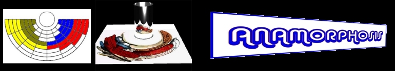
To view the conical mirror examples you need to make a mirror using a piece of aluminium coated thin plastic sheet. The examples have been created with a mirror having an angle of 60 degrees. As with the anamorphosis for putting an image on a cone, the cone is constructed from a sector of a circle.
Conical mirroramazon
LA = Entrance arm length LB = Exit arm length at λn βH = Angle between the perpendicular to the spectral plane and the grating normal LH = Perpendicular distance from the spectral plane to grating.
Efficiency in higher orders usually follows the first order efficiency curve. For a grating blazed in first order, the maximum efficiency for each of the subsequent higher orders decreases as the order k increases.
Table 1 shows how the angle of incidence and angle of diffraction vary depending on the deviation angle for a 1200 g/mm grating set to diffract 500 nm in a monochromator geometry.
Blazed grating groove profiles are calculated for the Littrow condition where the incident and diffracted rays are in auto collimation (i.e., α = β). The input and output rays, therefore, propagate along the same axis. In this case, at the “blaze” wavelength λB.
Light other than the wavelength of interest reaching a detector (often including one or more elements of “scattered light”) is referred to as stray light.
Fig. 4 shows a first order spectrum from 200 to 1000 nm spread over a focal field in spectrograph configuration. From Equation (1) with a grating of given groove density and for a given value of α and β:
In most monochromators, the location of the entrance and exit slits are fixed, and the grating rotates around a plane through the center of its face. The angle, DV, is, therefore, a constant determined by:
Conical mirrorfor sale
First order wavelengths between 200 and 380 nm may be monitored without filters because wavelengths below 190 nm are absorbed by air. If, however, the instrument is evacuated or N2 purged, higher order filters would again be required.
In most monochromators, the location of the entrance and exit slits are fixed, and the grating rotates around a plane through the center of its face. The angle, DV, is, therefore, a constant.
A grating blazed in first order is equally blazed in the higher orders. Therefore, a grating blazed at 600 nm in first order is also blazed at 300 nm in second order, and so on.
Monochromatic light has infinitely narrow spectral width. Good sources which approximate such light include single mode lasers and very low pressure, cooled spectral calibration lamps. These are also variously known as “line” or “discrete line” sources.
The efficiency also decreases the farther away from Littrow conditions in which the grating is used (e.g. α ≠ β). Holographic gratings may be designed with groove profiles that discriminate against high orders. This may be particularly effective in the UV and VIS using laminar groove profiles created by ion etching.
Ghosts are focused and imaged in the dispersion plane of the monochromator.Stray light of a holographic grating is usually up to a factor of ten times less than that of a classically ruled grating, is typically non-focused, and when present, radiates through 2π steradians.
Diffraction gratings are manufactured either classically with the use of a ruling engine, or holographically with the use of interference fringes generated at the intersection of two laser beams.
Images copyright © 1999-2010 by John Sharp. You may use the templates for your own use and for teaching purposes, but not for commercial purposes.
Rodmirror
Blaze is defined as the concentration of a limited region of the spectrum into any order other than the zero order. Blazed gratings are manufactured to produce maximum efficiency at designated wavelengths. A grating may, therefore, be described as “blazed at 250 nm” or “blazed at 1 micron,” etc. by appropriate selection of groove geometry.
Note: Just because a grating is “non-blazed” does not necessarily mean that it is less efficient! See Fig. 7 showing the efficiency curve for an 1800 g/mm sinusoidal grooved holographic grating.
Holographic gratings show no ghosts because there are no periodic ruling errors and, therefore, often represent the best solution to ghost problems.
As a general approximation, for blazed gratings the strength of a signal is reduced by 50% at two-thirds the blaze wavelength, and 1.8 times the blaze wavelength.
Theoretically, a 1200 g/mm grating with a width of 110 mm that is used in first order has a numerical resolving power R = 1200 × 110 = 132,000. Therefore, at 500 nm, the bandpass is equal to:
Remember, ghosts and subsequent stray light intensity are proportional to the square of order and groove density (n2 and k2 from Equation (17). Beware of using ruled gratings in high order or with high groove density.
It is easy to imagine that fine spectral detail would be more easily identified in the first instrument than the second. The second instrument demonstrates “low” dispersion compared to the “higher” dispersion of the first. Linear dispersion is associated with an instrument’s ability to resolve fine spectral detail.
A blazed grating is one in which the grooves of the diffraction grating are controlled to form right triangles with a “blaze angle, ω,” as shown in Fig. 5. However, apex angles up to 110° may be present especially in blazed holographic gratings. The selection of the peak angle of the triangular groove offers opportunity to optimize the overall efficiency profile of the grating.
The slit acts both as a locator for the tab and as an indicator for the position of the 180 degree sector for the mirror. When you have a suitable cone, place it on the circle in the printouts of the conical mirror examples and look directly above the apex.
Relative efficiency measurements require the mirror to be coated with the same material and used in the same angular configuration as the grating.
If the diffraction grating has periodic ruling errors, a ghost, which is not scattered light, will be focused in the dispersion plane. Ghost intensity is given by:
I have always been fascinated with anamorphic art and its likes. This year I wanted to do anamorphic art as a theme for my HND art and design. I was a bit weary as I could not find adequate information on it or how to understand it properly, only lots of images to see which are amazing and so inspirational, but nothing to show me how its done. Then I came across your page. I just wanted to say you have giving me the confidence to go ahead with anamorphisis as my theme and my mind is doing over time with all the ideas I have for this term. thank you.
Convexmirror
In order to use these templates, you will need a copy of the Adobe Acrobat reader. You can download a copy from the Adobe Website . How to Make a Conical Mirror
In a spectrograph, the linear dispersion for any wavelength other than the wavelength which is normal to the spectral plane will be modified by the cosine of the angle of inclination or tilt angle (γ) at wavelength λn. Fig. 3 shows a “flat field” spectrograph as used with a linear diode array.
Because bandpass is also determined by the slit width of the spectrometer and residual system aberrations, an achieved bandpass at this level is only possible in diffraction limited instruments, assuming an unlikely 100% of theoretical.


 Ms.Cici
 8618319014500