
Electrical and Computer Engineering - UAlberta Marketplace - lab kit
The gain relates the number of photoelectrons released to the gray levels displayed, and can be used to enhance contrast for low-light imaging.
Whenever light passes through any refractive object, it undergoes a certain amount of diffraction. The beams of light are scattered and do not reach the observers; furthermore, they do not have parallel rays of light, but rather scattered angles.
The laser beam will reflect off the secondary mirror and reach the primary mirror. A primary mirror usually has a small marking tape on it. The laser is aligned to hit this marker and the secondary mirror is then accordingly oriented and focused.
Field of viewmicroscope 40x
Acton optics and coatings provide ultra-precision optical components and coatings with an emphasis on the UV/VUV spectral regions.
A laser collimator allows one to conveniently align the optics of a reflecting telescope. First, you use the laser collimator to determine whether or not the secondary mirror is pointing directly at the center of the primary mirror.
There are many subcategories of UV light, each which need different sensor requirements. These include both physical and chemical sensor changes.
Where D is the full display image dimensions (either horizontal or vertical), and d is the target dimensions (either horizontal or vertical).
Calculatingfield of viewmicroscope Worksheet
This allows the FOV dimensions (i.e. vertical and horizontal distances) to be measured without knowing lens focal length or sensor size. The image created, including the target, is then displayed on a monitor, with the target image being a subset of the full image display. This allows the FOV to be approximated as:
To measure the FOV of UV, visible and infrared cameras, optical tests are commonly used. During the test, light is focused from a black body (an object that absorbs all light that falls on it) onto a test target at the focal place. By using a set of mirrors, a virtual image can be created that is at an infinitely far distance.
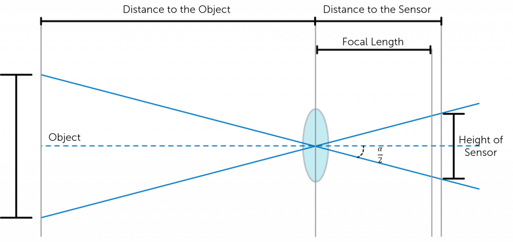
This means that the distance of the focal length is determined by how strongly the light is converged by the lens in order to focus the subject being imaged. This, in turn, influences the angle from the horizonal of light that can be captured by the lens. This is known as the angular field of view (AFOV) and is required to determine the overall FOV. The AFOV is the angle between any light captured at the horizonal, and any light captured at the edge (as shown in Figure 2). If you have a fixed sensor size, altering the focal length will alter the AFOV and therefore the overall FOV. A shorter focal length provides a larger AFOV view, and therefore a larger FOV. The same is true but vice versa for longer focal lengths, as indicated in Figure 2.
Collimated laser beams are very useful in laboratory setups, as the beam radius stays approximately constant, so the distances between optical components may be easily varied without applying extra optics, and excessive beam radii are avoided. Most solid-state lasers naturally emit collimated beams; a flat output coupler enforces flat wavefronts (i.e., a beam waist) at the output, and the beam waist is usually large enough to avoid excessive divergence. Edge-emitting laser diodes, however, emit strongly diverging beams and are therefore often equipped with collimation optics – at least with a fast-axis collimator, largely reducing the strong divergence in the “fast” direction. For fibers, a simple optical lens may often suffice for collimation, although the beam quality can be better preserved with an aspheric lens, particularly for single-mode fibers with a large numerical aperture.
what is thefield of viewat 100x in micrometers (μm)

Field of viewmicroscope Calculator
The focal length of a lens converges light so that the image of an object is focused onto the sensor. This determines the angular field of view, a parameter of the overall field of view. This is defined as the angle between any light captured at the horizontal and any light captured at the edge of the of the object. All of these parameters play a role in determining the FOV of a camera and can be measured using either trigonometry and the angular field of view, or via an optical test, in which a black body is utilized to create a virtual image
A laser can be defined as a device that generates a coherent beam of high-intensity monochromatic light. Most of the normal lasers that civilians use are laser diodes. Unlike their gas or crystal laser counterparts present in labs, laser diodes possess a severe level of divergence. A diode laser beam has low wavefront quality, severe astigmatism and also elliptical issues. Astigmatism in a laser diode usually refers to the level of aberration that a laser beam from a laser diode faces. Elliptical beams can also make the laser bleed a little on the edges; rather than forming a perfect point, it forms a small ellipse. Both of these problems can be corrected using a few optical corrections.
The concept of collimation is quite a unique one. It is used in laboratories to make corrections in a viewing angle, and also plays a vital role in astronomy. Today’s standard 8-inch telescopes can see distant quasars and galaxies, but how did such ordinary telescopes gain the clarity to view such distant objects? The answer is that today’s telescopes mostly come with laser or optical collimators. Before we take a look at what a laser collimator is, let’s first try to understand what the collimation of a beam actually means.
Field of view (FOV) is the maximum area of a sample that a camera can image. It is related to two things, the focal length of the lens and the sensor size. Figure 1 shows a comparison between the field of view and the size of the sensor. Assuming that the focal length of the lens is the same, the larger the sensor the larger the field of view.
Sensor size is determined by both the size of the pixels and number of pixels on the sensor. This can be optimized for each application, with larger sensors optimal for sensitivity limited applications, and smaller sensors optimal for resolution limited applications.
Field of viewmicroscope formula
The focal length of the lens describes the distance between the lens and the focused image on the sensor. As light passes through the lens it will either converge (positive focal length) or diverge (negative focal length), however within cameras the focal length is predominately positive. Shorter focal lengths converge the light more strongly (i.e. at a sharper angle) to focus the subject being imaged. Longer focal lengths, in comparison, converge the light less strongly (i.e. at a shallower angle) in order to focus the image.
Venkatesh is an Electrical and Electronics Engineer from SRM Institute of Science and Technology, India. He is deeply fascinated by Robotics and Artificial Intelligence. He is also a chess aficionado, He likes studying chess classics from the 1800 and 1900’s. He enjoys writing about science and technology as he finds the intricacies which come with each topic fascinating.
See how others are using our high-performance cameras, spectrographs and optics-based solutions to advance their research and application.
The collimation of a laser is done for a very good reason. It helps to theoretically align the focus of the image at infinity. This helps to increase the clarity of far-off celestial objects. Let’s consider a theoretical example that may explain why a laser is used to collimate in telescopes.
A collimator is a device that narrows a beam of light. The narrowing of a beam of light can have two meanings. The first one means arranging the beam of light in a particular direction. The second means reducing the spatial cross-section of a beam to become smaller.
Field of viewmicroscope 4x
Howtocalculate field of viewdiameter
There are two processes which can be used to enhance UV sensitivity for wavelengths >200 nm: UV photon conversion, and anti-reflection coatings.
A laser collimator is a device that is used to narrow a beam of light. It can be used to arrange the beam of light in a particular direction, or to reduce the spatial cross-section of a beam to make it smaller. A laser collimator is often used to collimate a laser beam, which means to convert a beam of scattered light into a beam of parallel rays of light.
Field of viewmicroscope 10X
The most simple and popular way to collimate a laser diode beam is by using a single aspheric lens. The larger the focal length of this lens, the larger the beam diameter will be after collimation. Furthermore, if a certain beam adjustment must be made, for example, to expand the beam radius of a collimated beam, a two-lens system is often used – a so-called telescope. One lens with a negative focal length and the other with a positive one creates a setup to collimate and expand or shrink the beam. To correct the elliptical problem, a collimated elliptical beam can be circularized by either expanding in the slow axis direction of the ellipsis or compressing in the fast axis direction.
Field of view defines the maximum area of a sample that a camera can image, determined by the focal length of the lens and the sensor size.
The first thing you do is shine the laser collimator through the tube of the telescope. It should be ensured that the laser collimator is firmly in place without any movement. This will ensure the proper alignment of the laser collimator without any flex or flop.
The sensor size is determined by both the number of pixels on the sensor, and the size of the pixels. Different sized pixels are used for different applications, with larger pixels used for higher sensitivity, and smaller pixels used for higher spatial resolution (find out more on Pixel Size and Camera Resolution).
The problem of collimating occurs when distant objects appear as point sources. Unfortunately, nothing is ever a true point source and the size of the source must be included in any calculation if the point source has a radius of y1 and a maximum ray of angle θ1. If we collimate the output from this source using a lens with focal length f, the result will be a beam with a radius y2 = θ1f and divergence angle θ2 = y1/f. Note that, no matter what lens is used, the beam radius and beam divergence have a reciprocal relation. Thus, if the focal point were to be infinity, that would result in the ray angle being zero, thereby collimating the beam of light.
A collimated beam of light, on the other hand, is one that has extreme parallel rays of light. Thus, we can define collimation as the process of converting scattered light into a beam of light with a high number of parallel rays. A collimated beam of light is a beam (typically a laser beam) with a low beam divergence so that the beam radius does not undergo significant changes within moderate propagation distances. In the simple (and frequently encountered) case of Gaussian beams, this means that the Rayleigh length must be long in comparison to the envisaged propagation distance.
Figure 3 shows a simplified version of how these assumptions allow for AFOV calculation. By using trigonometry, the AFOV can be expressed as:


 Ms.Cici
 8618319014500