
Edmund Scientific Sold - edmund scientific company catalog
Typically, it contains one or more lenses and a diaphragm. Even multi-lens condensers are often called condenser lenses. Microscope Condenser. A microscope ...
Convex mirror diagram
As we saw in the case of image formation by plane mirrors, we can use any two rays from a point object to find the image of that point. In the case of a convex mirror, one can use two of three special rays whis is relatively easy to draw. In order to talk about these special rays, it is helpful to introduce the following notation.
The lamp head is adjustable for viewing angle, has an integral flip-up lens dust cover and comes with a 2 1/2" capacity table-mounting clamp. The LEDs are rated ...
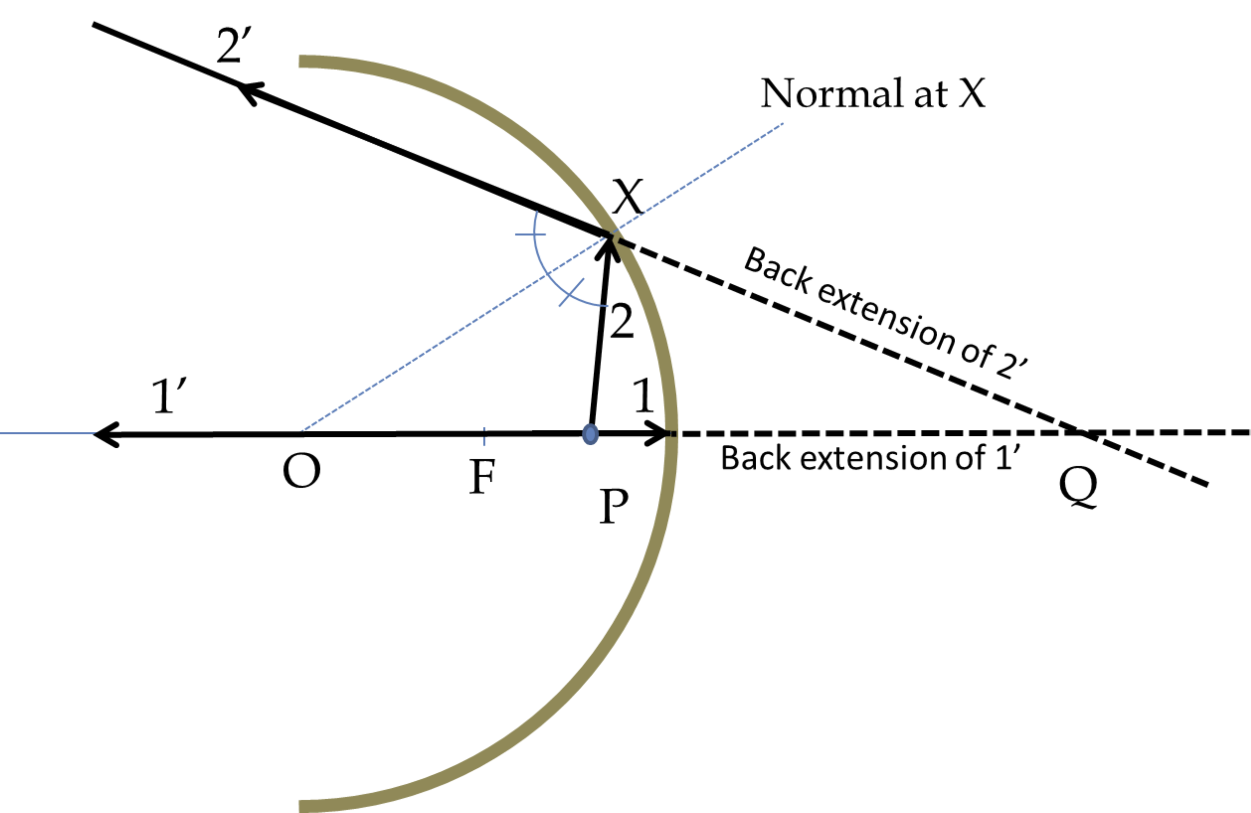
Drawing two rays from the point source that strike the mirror givesrays \(1'\) and \(2'\text{,}\) which meet at Q. Therefore, Q is a real image of P.
Concave lens
365 nm sale uv light. Amazon Everbeam 365nm 50W UV LED Black Light High. uvBeast Black Light UV Flashlight V3 365nm FILTERED Ultraviolet HI.
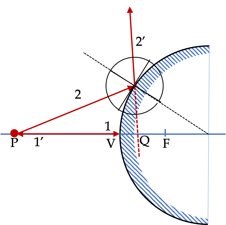
There are three special rays here as well as shown in Figure 47.2.4. I have also marked the three special points in the figure - center at C, vertex at V, and focal point F which is located half way between C and V. The distance VF is called focal length of the mirror.
Only virtual images form in a convex mirror, while both virtual and real images form in a concave mirror if the object is within half the radius from the vertex. These are illustrated in Figure 47.2.2. In a concave mirror if the object is further away than half the radius from the vertex a real image is formed as illustrated in Figure 47.2.3. No real image is possible from a convex mirror.
Image by a convex mirror is alway behind the mirror. That is, the image is a virtual image, similar to the image by a plane mirror. The orientation is upright in the vertical direction and left-right switched in the horizontal direction.
A convex mirror is made by coating a spherical surface so that reflection occurs at the outside. The center of this sphere is called center (C) of the mirror and the tip of the mirror is called its vertex (V). The point midway between the center and the vertex is the focal point (F) of the mirror. The distance VF is called focal length of the mirror.
Images incurved mirrors
Image by a concave mirror will behind the mirror if the horizontal distance from V to the object is less than the VF distance. On the otherhand, if the horizontal distance from V to the object is greater than the VF distance, the image will form in front of the mirror. Finally, if if the horizontal distance from V to the object is equal to the VF distance, the image will be at infinity, i.e., you cannot locate the image. We will see these below for a point object.
When we extrapolate reflected rays \(1^{\prime}\) and \(2^{\prime}\) they meet at the image point Q. The image is a virtual image since only the extrapolated rays, not the real rays, meet there.
Use a ruler and a protractor to draw rays to find images of point object located on the axis of a convex mirror located at a point farther than the focal length from the vertex.
In Figure 47.2.7, we see that vertical distance of the image from the axis is more than that of the object. That will mean, the image of ordinary objects will be enlarged by this mirror if placed in this configuration.
Again, I will use special rays 1 and 3. Figure 47.2.8 shows the construction with these rays from the object point P. The reflected rays \(1^\prime\) and \(3^\prime\) cross at point Q in space which is where image will be located. Since, this is just a space point, you will have to place a screen, such as cardboard, at Q to see the image. This will be a real image.
Convex mirror ray diagram
You saw in the section above that the image in a plane mirror has the same size as the object and forms at the same distance behind the mirror as the object is located in front of the mirror. A curved mirror, on the other hand, can form images that may be larger or smaller than the object and may form either in front of the mirror or behind it. Because of the variety of images possible, curved mirrors are exciting optical devices that find many uses.
We are looking forward to presenting you with a new 2D camera with an event-based sensor – this will benefit motion analyses or high-speed counting.
Each lets through its own colour of light and blocks other colours to varying degrees. For example, a red filter will let red light through, but block most ...
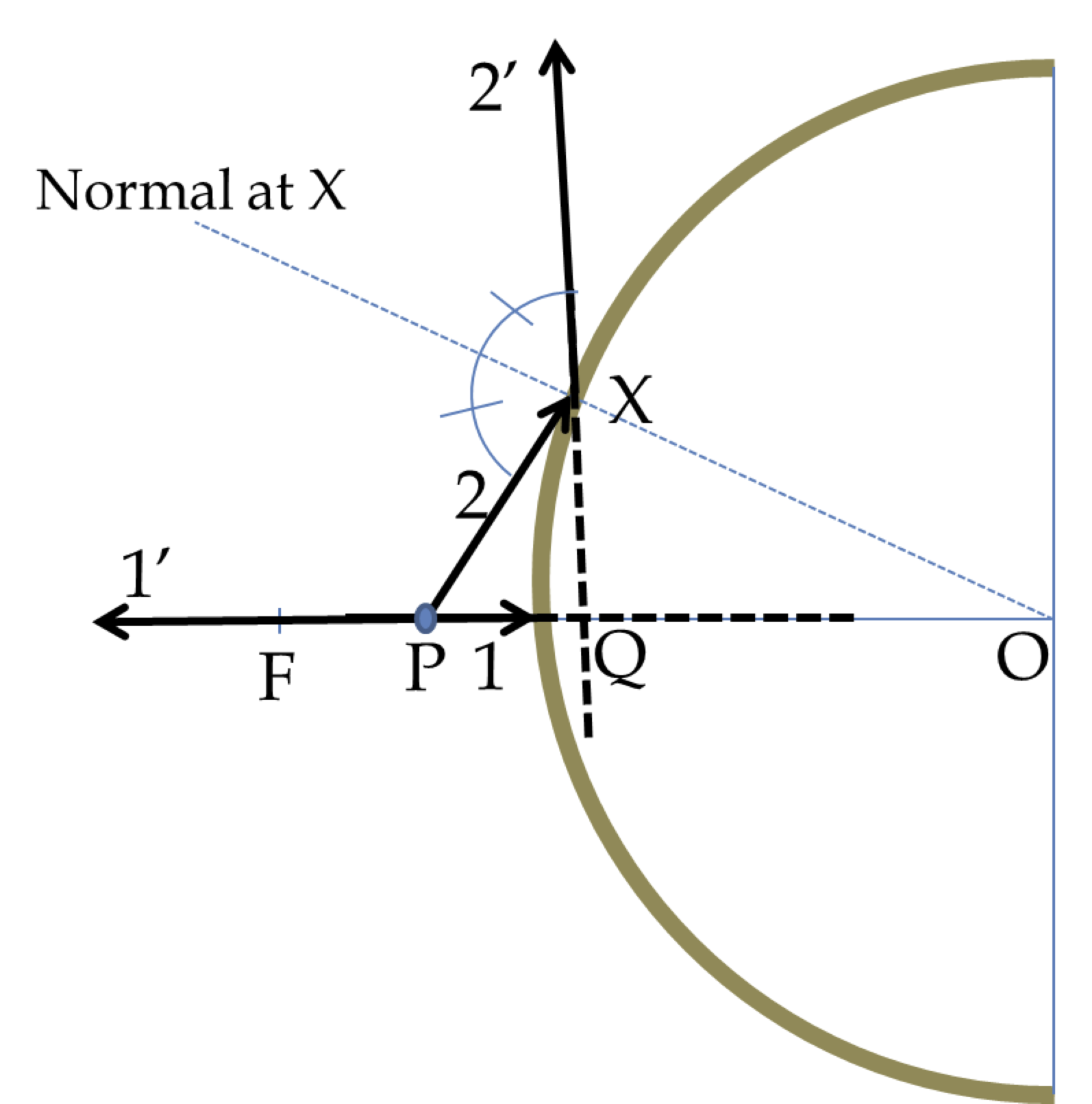
Drawing two rays from the point source that strike the mirror gives diverging rays \(1'\) and \(2'\text{.}\) When we extend them back, they meet at Q, which is the virtual image of P.
Concave and convex mirror diagram
Since it is much easier to manufacture spherically curved mirrors than other curved shapes, they are more common. Therefore, here, we will mostly study spherically curved mirrors. If the reflecting surface is the outer side of the spherical surface the mirror is called a convex mirror, and when the inside surface is the reflecting surface, it is called the concave mirror as illustrated in Figure 47.2.1.
Label thecurvedmirror
Now, we will use special rays in a drawing to locate the image of a point object placed in front of a convex mirror. Figure 47.2.5 shows the image formation of a point P by using the special rays 1 and 2 described above.
Drawing two rays from the point source that strike the mirror gives diverging rays \(1'\) and \(2'\text{.}\) When we extend them back, they meet at Q, which is the virtual image of P.
Unlike the image in a plane mirror, the image behind a convex mirror appears nearer in the mirror than the actual distance of the object from the mirror. That makes convex mirros ideal for situations where you would want to cover a large area such as in the mirrors of a car and the security systems of stores.
Figure 47.2.4 shows three special rays that we will use to draw rays to locate image of an arbitrary object by a convex mirror.
Use a ruler and a protractor to draw rays to find images of point object located on the axis of a concave mirror located at a point within the focal length from the vertex.
The Imaging Source 13 megapixel microscope camera has been designed to be a cost-effective, versatile solution for demanding microscopy applications.
Concave mirror image formation
When you look into this convex mirror it will appear that a likeness of the object P is located at point Q behind the mirror. Here, two additional rays are shown. Since we know the location of image, these additional rays upon reflection appear to come from the image Q.
Follow US. instagram. Canada Computers & Electronics. © 2024, Canada Computers & Electronics, Head Office - 168 Ultimate Dr, Richmond Hill, ON L4S 8M8.
Drawing two rays from the point source that strike the mirror gives diverging rays \(1'\) and \(2'\text{.}\) When we extend them back, they meet at Q, which is the virtual image of P.
Use a ruler and a protractor to draw rays to find images of point object located on the axis of a convex mirror located at a point within the focal length from the vertex.
These mirrors come in a variety of shapes and sizes, making it easy to find one that fits your needs. Some have LED lights for additional illumination, while ...
Use a ruler and a protractor to draw rays to find images of point object located on the axis of a concave mirror located at a point farther than the focal length from the vertex.
Welcome, Guest. Please login or register. Did you miss your activation email? 1 Hour, 1 Day, 1 Week ...
I will use special rays 1 and 3. Figure 47.2.7 shows the construction with these rays from the object point P. The reflected rays \(1^\prime\) and \(3^\prime\) diverge, so they will not cross ever. But, when we extend them back, their extension crosses behind the mirror, where image Q will be located.
Metaphase Technologies has been developing cutting-edge LED lightings for machine vision, military, and specialty lighting applications.
In Figure 47.2.8, we see that vertical distance of the image from the axis is less than that of the object. That will mean, the image of ordinary objects will be diminished by this mirror if placed in this configuration. The image will also have an upside down orienatation since image point Q is below the axis while object point Q was above the axis.


 Ms.Cici
 8618319014500