
Edmond H. Grin | 1 Artworks at Auction - edmond grin
The shoulder is located at the base of the objective threading and marks the beginning of the exposed objective body when it is fully threaded into a nosepiece or other objective mount.
High power objective
A variety of specimens exhibit autofluorescence (without the application of fluorochromes) when they are irradiated, a phenomenon that has been thoroughly exploited in the fields of botany, petrology, and the semiconductor industry. In contrast, the study of animal tissues and pathogens is often complicated with either extremely faint or bright, nonspecific autofluorescence. Of far greater value for the latter studies are added fluorochromes (also termed fluorophores), which are excited by specific wavelengths of irradiating light and emit light of defined and useful intensity. Fluorochromes are stains that attach themselves to visible or sub-visible structures, are often highly specific in their attachment targeting, and have a significant quantum yield (the ratio of photon absorption to emission). The widespread growth in the utilization of fluorescence microscopy is closely linked to the development of new synthetic and naturally occurring fluorophores with known intensity profiles of excitation and emission, along with well-understood biological targets.
Here, the Design Magnification is the magnification printed on the objective, fTube Lens in Microscope is the focal length of the tube lens in the microscope you are using, and fDesign Tube Lens of Objective is the tube lens focal length that the objective manufacturer used to calculate the Design Magnification. These focal lengths are given by the table to the right.
How do you switch objectivesin witcher 3
If an objective is used for water dipping, water immersion, or oil immersion, a second colored ring may be placed beneath the magnification identifier. If the objective is designed to be used with water, this ring will be white. If the objective is designed to be used with oil, this ring will be black. Dry objectives lack this identifier ring entirely. See the table to the right for a complete list of immersion identifiers.
The resolution of an objective refers to its ability to distinguish closely-spaced features of an object. This is often theoretically quantified by considering an object that consists of two point sources and asking at what minimum separation can these two point sources be resolved. When a point source is imaged, rather than appearing as a singular bright point, it will appear as a broadened intensity profile due to the effects of diffraction. This profile, known as an Airy disk, consists of an intense central peak with surrounding rings of much lesser intensity. The image produced by two point sources in proximity to one another will therefore consist of two overlapping Airy disk profiles, and the resolution of the objective is therefore determined by the minimum spacing at which the two profiles can be uniquely identified. There is no fundamental criterion for establishing what exactly it means for the two profiles to be resolved and, as such, there are a few criteria that are observed in practice. In microscopic imaging applications, the two most commonly used criteria are the Rayleigh and Abbe criteria. A third criterion, more common in astronomical applications, is the Sparrow criterion.
Thorlabs offers a High-Resolution Plan Apochromatic Improved Visible (APO VIS+) Microscope Objective for 400 to 1100 nm which provides axial color correction over a wide field of view with no vignetting over the entire field. Compared to common apochromatic microscope objectives, which are typically axial color corrected from the 436 nm (g-line) to 656 nm (C-line), our PLAN APO VIS+ objective has an extended corrected wavelength range from 436 nm (g-line) to 850 nm. The objective is designed for use with a tube lens focal length of 200 mm and has optical elements that are AR-coated for improved transmission between 400 nm and 1100 nm. For more details on these objectives, please click the info icon () below. Our 50X objective has a high numerical aperture (NA) of 0.75, making it ideal for applications requiring high-resolution such as laser focusing; brightfield, darkfield, and fluorescence microscopy; and two-photon imaging. Thorlabs offers the objective case (Item #s OC2M26 and OC24) separately as a replacement if the case shipped with each of these objectives is lost or broken.
The magnification of a system is the multiplicative product of the magnification of each optical element in the system. Optical elements that produce magnification include objectives, camera tubes, and trinocular eyepieces, as shown in the drawing to the right. It is important to note that the magnification quoted in these products' specifications is usually only valid when all optical elements are made by the same manufacturer. If this is not the case, then the magnification of the system can still be calculated, but an effective objective magnification should be calculated first, as described below.
A cover glass, or coverslip, is a small, thin sheet of glass that can be placed on a wet sample to create a flat surface to image across.
Our 1X telecentric objective is ideal for machine vision applications and features a removable magnetic waveplate that minimizes back reflections when used with an epi-illuminated system, thus enabling an increase in contrast; see the image to the right. Our 2X and 4X objectives pair low magnification with NAs of 0.10 and 0.20, respectively, making them ideal for widefield imaging. Lastly, our 10X and 15X objectives are designed for multiphoton imaging applications and provide excellent transmission out to 1300 nm. The 10X and 15X objectives have correction collars that allow adjustment for spherical aberrations introduced by imaging through aqueous solutions or thick cover glasses, without the need for water dipping or oil immersion. The TL15X-2P objective additionally features a locking mechanism to fix the correction collar in place for improved repeatability.
The filter nomenclature employed by Nikon derives from a mixture of terms dating back to the early 1990s. At that time, all of the Nikon complementary filter combinations were produced using the hard coat sputter technique, but many of the currently available filters take advantage of newer softer coating methods. Although soft coats are more susceptible to humidity and heat degradation, and must be handled more carefully than hard coat filters, they exhibit higher blocking value optical densities and provide greater ease of fine-tuning specific wavelength bands. Understanding the Nikon filter combination code nomenclature provides a mechanism to quickly determine whether a particular set will perform adequately for a specific fluorophore.
Other popular advanced fluorescence techniques, such as fluorescence resonance energy transfer (FRET) and fluorescence recovery after photobleaching (FRAP), as well as spectroscopy, are often combined with total internal reflection to achieve additional information, as is possible with the Nikon Ti2-LAPP modular illumination system. The result is a very powerful tool for the study of individual fluorophores and fluorescently labeled molecules. The advantages resulting from the study of the properties of single molecules are only beginning to be appreciated. Thus, the current range of optical microscopy now extends from the single molecule to the entire animal.
The excited state relaxation process of quenching results in reduced fluorescence intensity through a variety of mechanisms involving non-radiative energy loss and frequently occurs as a result of oxidizing agents or the presence of salts or heavy metals or halogen compounds. In some cases, quenching results from the transfer of energy to another molecule (termed the acceptor), which resides physically close to the excited fluorophore (the donor), a phenomenon known as fluorescence resonance energy transfer (FRET). This particular mechanism has become the basis for a useful technique involving the study of molecular interactions and associations at distances far below the lateral resolution of the optical microscope.
Example 1: Camera MagnificationWhen imaging a sample with a camera, the image is magnified by the objective and the camera tube. If using a 20X Nikon objective and a 0.75X Nikon camera tube, then the image at the camera has 20X × 0.75X = 15X magnification.
Field curvature (or Petzval curvature) describes the case where an objective's plane of focus is a curved spherical surface. This aberration makes widefield imaging or laser scanning difficult, as the corners of an image will fall out of focus when focusing on the center. If an objective's class begins with "Plan", it will be corrected to have a flat plane of focus.
The camera sensor dimensions can be obtained from the manufacturer, while the system magnification is the multiplicative product of the objective magnification and the camera tube magnification (see Example 1). If needed, the objective magnification can be adjusted as shown in Example 3.
Each objective is engraved with its class, magnification, numerical aperture, wavelength range, a zero (noting that it is to be used to image a sample without a cover glass), and optical field number. For an explanation of the defining properties of these objectives, please see the Objective Tutorial tab.
Presented in Figure 6 are the transmission profiles for a typical fluorescence filter combination used in modern microscopes. The excitation filter spectrum (red curve) exhibits a high level of transmission (approximately 75 percent) between 450 and 490 nanometers with a center wavelength (CWL) of 470 nanometers. The dichromatic mirror (yellow curve) reflects wavelengths in the region of the excitation spectrum, while passing higher and lower wavelengths with relatively high efficiency. Note that zero percent transmission on the dichromatic mirror curve corresponds to 100 percent reflection. The pronounced dip in the transmission profile between 450 and 500 nanometers, which represents a peak in reflectance, serves to reflect the band of wavelengths passing from the excitation filter at a 90-degree angle and onto the specimen. The final component in the optical train, an emission or barrier filter (white curve), transmits wavelengths in the green visible light region, in the range between 520 and 560 nanometers. Boundaries between transmitted and reflected wavelength bands of the various superimposed spectra are designed to be as steep as possible to assure nearly complete separation of the reflected and transmitted wavelengths. A pattern of sinusoidally rising and falling spikes appearing in the dichromatic mirror spectrum is a common effect of the thin-film deposition process known as ringing. The performance of this filter combination is remarkable and is a clear demonstration of the rapid advances being achieved in thin film interference filter technology.
Thorlabs offers Mitutoyo Plan Apochromat Objectives with 5X, 7.5X, 10X, 20X, 50X, or 100X magnification. They feature a flat field of focus and chromatic correction over their operating ranges: either 436 nm to 656 nm or 480 nm to 1800 nm. The long working distance provides a wide space between the lens surface and the object making them ideal for machine vision applications. Each objective is engraved with its class, magnification, numerical aperture, a zero (noting that it is to be used to image a sample without a cover glass), and the tube lens focal length for which the specified magnification is valid. For an explanation of the defining properties of these objectives, please see the Objective Tutorial tab. If the case shipped with each of these objectives is lost or broken, Thorlabs offers an objective case (item #s OC2M26 and OC24) that can be used as a replacement.
The first letter in the Nikon proprietary alphanumeric filter designation code indicates the wavelength excitation spectral region (for example, UV, V, B, and G, which are simple abbreviations for ultraviolet, violet, blue, and green, respectively). The number following the excitation code relates to the excitation filter passband width: 1 for narrow band excitation, 2for medium and wide band excitation, and 3 for very wide band excitation. Finally, one or more letters following the excitation bandpass size number identifies the barrier filter characteristics. The code letter A indicates a standard longpass barrier filter with the lowest cut-on wavelength, while B designates a higher cut-on wavelength value for a longpass emission filter. Bandpass emission filters are identified with the letter E (referring to the term "enhanced") to indicate their superior performance with regard to eliminating crossover. The E/C filters are soft coat interference combinations designed for best performance with specific probes, such as DAPI, FITC, TRITC, and Texas Red.
The era when optical microscopy was purely a descriptive instrument or an intellectual toy is past. At present, optical image formation is only the first step toward data analysis. The microscope accomplishes this first step in conjunction with electronic detectors, image processors, and display devices that can be viewed as extensions of the imaging system. Computerized control of focus, stage position, optical components, shutters, filters, and detectors is in widespread use and enables experimental manipulations that were not humanly possible with mechanical microscopes. The increasing application of electro-optics in fluorescence microscopy has led to the development of optical tweezers capable of manipulating sub-cellular structures or particles, the imaging of single molecules, and a wide range of sophisticated spectroscopic applications.
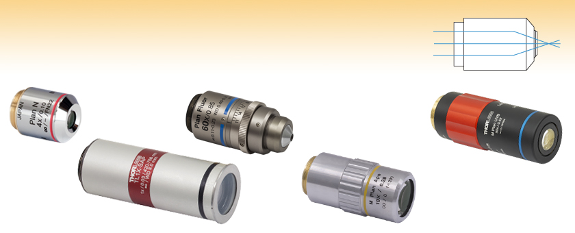
Thorlabs offers dry objectives made in house, as well as objectives from Olympus, Nikon, and Mitutoyo. Super apochromat, plan achromat, plan apochromat VIS+, plan apochromat, and plan fluorite (also called plan semi-apochromat or plan fluor) designs are available. For details about the differences between these types of objectives, please see the Objective Tutorial tab above.
How do you switch objectivesin a microscope
Abbreviations employed by manufacturers to identify the properties of their excitation filters include: UG (ultraviolet glass) and BG (blue glass). Shortpass filters often are denoted as KP(K is an abbreviation for kurz, which means "short" in German) or simply as SP. Several manufacturers now label their interference filters with the designation IF. Narrow band excitation interference filters are especially helpful if the Stokes' shift is small.
Most of the scattered excitation light reaching the dichromatic mirror is reflected back toward the light source, although a minute quantity often passes through and is absorbed by the internal coating of the mirror block. Before the emitted fluorescence can reach the eyepiece or detector, it must first pass through the barrier or suppression filter. This filter blocks (suppresses) any residual excitation light and passes the desired longer emission wavelengths. In most reflected light illuminators, the excitation filter, dichromatic mirror, and barrier filter are incorporated into an optical block (often referred to as a cube), as illustrated in Figure 2. Modern fluorescence microscopes are capable of accommodating between four and six fluorescence cubes (usually on a revolving turret or through a slider mechanism; see Figure 1) and permit the user to easily attach replacement aftermarket excitation and barrier filters, as well as dichromatic mirrors.
As presented in Figure 1, the reflected light vertical illuminator comprises an arc-discharge lamphouse at the rear end (usually a mercury or xenon burner). Excitation light travels along the illuminator perpendicular to the optical axis of the microscope, passes through collector lenses and a variable, centerable aperture diaphragm, and then through a variable, centerable field diaphragm (see Figure 1). The light then impinges upon the excitation filter where selection of the desired band and blockage of unwanted wavelength occurs. The selected wavelengths, after passing through the excitation filter, reach the dichromatic beamsplitting mirror, which is a specialized interference filter that efficiently reflects shorter wavelength light and efficiently passes longer wavelength light. The dichromatic beamsplitter is tilted at a 45-degree angle with respect to the incoming excitation light and reflects this illumination at a 90-degree angle directly through the objective optical system and onto the specimen. Fluorescence emission produced by the illuminated specimen is gathered by the objective, now serving in its usual image-forming function. Because the emitted light consists of longer wavelengths than the excitation illumination, it is able to pass through the dichromatic mirror and upward to the observation tubes or electronic detector.
When imaging a sample with a camera, the dimensions of the sample area are determined by the dimensions of the camera sensor and the system magnification, as shown by Equation 2.
The Abbe theory describes image formation as a double process of diffraction [2]. Within this framework, if two features separated by a distance d are to be resolved, at a minimum both the zeroth and first orders of diffraction must be able to pass through the objective's aperture. Since the first order of diffraction appears at the angle: sin(θ1) = λ/d, the minimum object separation, or equivalently the resolution of the objective, is given by d = λ/n*sin(α), where α is the angular semi-aperture of the objective and a factor of n has been inserted to account for the refractive index of the imaging medium. This result overestimates the actual limit by a factor of 2 because both first orders of diffraction are assumed to be accepted by the objective, when in fact only one of the first orders must pass through along with the zeroth order. Dividing the above result by a factor of 2 and using the definition of the numerical aperture (NA = n*sin(α)) gives the famous Abbe resolution limit:
Michael W. Davidson - National High Magnetic Field Laboratory, 1800 East Paul Dirac Dr., The Florida State University, Tallahassee, Florida, 32310.
Dichromatic beamsplitters also are described by numerous abbreviations including CBS for a chromatic beam splitter, DM for dichroic mirror, TK for "teiler kante", German for edge splitter, FT for "farb teiler" (German for color splitter), and RKP for reflection short pass. All of these terms should be considered interchangeable, and modern dichromatic beamsplitters are always manufactured with interference coatings on optical glass (as opposed to organic or metallic dyes). The interference thin films are designed to produce high reflectivity for shorter wavelengths and high transmission for longer wavelengths. Dichromatic beamsplitters are oriented at a 45-degree angle to the path of the excitation light entering the optical block through the reflected light fluorescence illuminator. Their primary function is to re-direct the selected excitation (shorter) wavelengths through the objective and onto the specimen. These specialized filters also have the additional functions of passing longer wavelength fluorescence emission to the barrier filter, and reflecting any scattered excitation light back in the direction of the lamphouse.
Presented in Figure 4 is a typical example of photobleaching (fading) observed in a series of digital images captured at different time points for a multiply-stained culture of Indian Muntjac deer epidermis fibroblast cells. The nuclei were stained with a bis-benzimidazole derivative (Hoechst 33258; blue fluorescence), while the mitochondria and actin cytoskeleton were stained with MitoTracker Red CMXRos (red fluorescence) and a phalloidin derivative conjugated to Alexa Fluor 488 (green fluorescence), respectively. Time points were taken in two-minute intervals using a fluorescence filter combination with bandwidths tuned to excite the three fluorophores simultaneously while also recording the combined emission signals. Note that all three fluorophores have a relatively high intensity in Figure 4(a), but the Hoechst fluorophore (blue) intensity starts to drop rapidly at two minutes and is almost completely gone at 6-8 minutes. The mitochondrial and actin stains are more resistant to photobleaching, but the intensity of both drops significantly over the course of the timed sequence (10 minutes).
Illumination modules for adding photo-stimulation (conversion/activation), FRAP, and TIRF capability to Nikon imaging systems.
Using an immersion fluid with a high refractive index allows objectives to achieve numerical apertures greater than 1.0. However, if an immersion objective is used without the fluid present, the image quality will be very low. Objectives following ISO 8578: Microscopes -- Marking of Objectives and Eyepieces will be labeled with an identifier ring to tell the user what immersion fluid the objective is designed to be used with; a list of ring colors can be found in the table above.
Each objective is designed for use with a tube lens focal length of 200 mm and is compatible with our DIY Cerna® Systems. They use M25 x 0.75 threading; to use these objectives with a different thread standard, please see our microscope objective thread adapters.
The labeling area for an objective usually falls in the middle of the objective body. The labeling found here is dictated by ISO 8578: Microscopes -- Marking of Objectives and Eyepieces, but not all manufacturers adhere strictly to this standard. Generally, one can expect to find the following information in this area:
High power objective microscope function
In the image below, two Airy disks are shown separated by the Abbe resolution limit. Compared to the Rayleigh limit, the decrease in intensity at the origin is much harder to discern. The horizontal line cut to the right shows that the intensity decreases by only ≈2%.
The fluorophore emission (or absorption) intensity peak is usually lower in wavelength and magnitude than that exhibited by the excitation peak, and the emission spectral profile (curve) is often a mirror image (or nearly so) of the excitation curve, but shifted to longer wavelengths, as illustrated in Figure 3 for Alexa Fluor 555, a useful probe that absorbs light in the yellow-green region and produces yellow-orange emission. In order to achieve maximum fluorescence intensity, a fluorophore (often termed a dye) is usually excited at wavelengths near or at the peak of the excitation curve, and the widest possible range of emission wavelengths that include the emission peak are selected for detection. The selection of excitation and emission wavelengths is typically based on interference filters (Figure 2). In addition, the spectral response of a microscope optical system will also depend on such factors as glass transmission efficiency (due to anti-reflection coatings), the number of lens and mirror elements, and the responsivity of the detector system.
An unfortunate consequence of low emission levels in most fluorescence microscopy applications is that the number of photons that reach the eye or camera detector is also very low. In most cases, the collection efficiency of optical microscopes is less than 30 percent and the concentration of many fluorophores in the optical path ranges in the micromolar or nanomolar regions. In order to generate sufficient excitation light intensity to produce detectable emission, powerful compact light sources, such as high-energy short arc-discharge lamps, are necessary. The most common lamps are mercury burners, ranging in wattage from 50 to 200 Watts, and the xenon burners that range from 75 to 150 Watts (see Figure 5). These light sources are usually powered by an external direct current supply, furnishing enough start-up power to ignite the burner through ionization of the gaseous vapor and to keep it burning with a minimum of flicker.
Objectives with very small working distances may have a retraction stopper incorporated into the tip. This is a spring-loaded section which compresses to limit the force of impact in the event of an unintended collision with the sample.
The absorption and subsequent re-radiation of light by organic and inorganic specimens is typically the result of well-established physical phenomena described as being either fluorescence or phosphorescence. The emission of light through the fluorescence process is nearly simultaneous with the absorption of the excitation light due to a relatively short time delay between photon absorption and emission, ranging usually less than a microsecond in duration. When emission persists longer after the excitation light has been extinguished, the phenomenon is referred to as phosphorescence.
Vibrational energy is lost when electrons relax from the excited state back to the ground state. As a result of the energy loss, the emission spectrum of an excited fluorophore is usually shifted to longer wavelengths when compared to the absorption or excitation spectrum (note that wavelength varies inversely to radiation energy). This well-documented phenomenon is known as Stokes’ Law or Stokes' shift. As Stokes' shift values increase, it becomes easier to separate excitation from emission light through the use of fluorescence filter combinations.
The efficiency with which a particular fluorophore absorbs a photon of the excitation light is a function of the molecular cross-section, and the likelihood of absorption is known as the extinction coefficient. Larger extinction coefficients indicate that the absorption of a photon (or quantum) in a given wavelength region is more likely. The quantum yield denotes the ratio of the number of quanta emitted compared to those absorbed (and is usually a value between 0.1 and 1.0). Quantum yield values below 1 are the result of the loss of energy through nonradiative pathways, such as heat or a photochemical reaction, rather than the re-radiative pathway of fluorescence. Extinction coefficient, quantum yield, mean luminous intensity of the light source, and fluorescence lifetime are all important factors that contribute to the intensity and utility of fluorescence emission.
Cyberpunkswitch objectives
Nikon offers light sources for a broad range of imaging needs, from coaxial systems for stereomicroscopy to LED-based illuminators for epi-fluorescence applications, and powerful laser units for advanced imaging applications. Many of our light solutions include unique implementations and can be triggered for high-speed control.
Multiple optical elements, including the microscope objective, tube lens, and eyepieces, together define the magnification of a system. See the Magnification & FOV tab to learn more.
All objectives featured on this page are compatible with our microscope nosepiece modules for DIY Cerna® systems, which accept RMS, M25 x 0.75, or M32 x 0.75 objective threading. Parfocal lengths can be matched by using our parfocal length extenders. The Olympus microscope objectives can be mounted directly to our fiber launch systems, or mounted into our 30 mm cage system using the CP42(/M) RMS-threaded cage plate, which is also post mountable. They can also be mounted to any of our multi-axis platforms or translation stages using an HCS013 RMS mount. Please note that the multi-axis platforms and translation stages need a 3 mm wide central keyway for the HCS013 RMS mount.
The fluorescence emission that results from the light flux discussed above depends on the absorption and emission characteristics of the fluorophore, its concentration in the specimen, and the optical path length of the specimen. In mathematical terms, the fluorescence produced (F) is given by the equation:
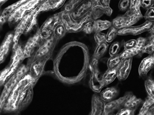
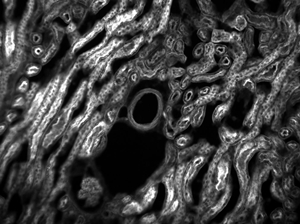
The images of a mouse kidney below were all acquired using the same objective and the same camera. However, the camera tubes used were different. Read from left to right, they demonstrate that decreasing the camera tube magnification enlarges the field of view at the expense of the size of the details in the image.
These objectives are designed for use from -18 °C (0 °F) to 60 °C (140 °F) and are not recommended for use at extreme temperatures.
Immersion objectives are similar to water-dipping objectives; however, in this case the sample is under a cover glass. A drop of fluid is then added to the top of the cover glass, and the tip of the objective is brought into contact with the fluid. Often, immersion objectives feature a correction collar to adjust for cover glasses with different thicknesses. Immersion fluids include water, oil (such as MOIL-30), and glycerol.
The duration of fluorescence emission depends upon the rate of fluorophore destruction as a result of photobleaching. For fluorescein in an oxygenated saline solution, measurements indicate that each molecule can only emit about 36,000 photons before being destroyed. In a deoxygenated environment, the rate of photodestruction diminishes about tenfold, so 360,000 photons are produced per fluorescein molecule. The entire dye pool, in this example (7.2 million molecules), would then be capable of producing a minimum of 2.6 x 10 × E(11) and a maximum of 2.6 x 10 × E(12) photons. Assuming the emission rate of 100,000 photons per second per molecule calculated above, fluorescence could continue for only 0.3 to 3 seconds before photodestruction. In the case where 10 percent of the photon flux is detected, a signal of 7.2 x 10 × E(10) electrons per second would be obtained.
The objectives have external W26 x 0.706 threads; to use these objectives with a different thread standard, please see our microscope objective thread adapters. These objectives do not feature adjustment to correct for cover glass thickness and should be used without a cover slip.
When choosing a microscope objective, it is important to keep in mind that objectives are often designed to integrate with a particular manufacturer's microscopes. Before interchanging objectives, be sure to check the design tube lens focal length and the threading type of the objectives. A full list of specifications for each objective can be found in the Specs tab above. Please note that the performance of each objective may vary from the engraved specifications when integrated with components and systems from different manufacturers. See the Magnification and FOV tab for more information.
How do you switch objectivesreddit
Their designation as plan achromats indicates that they are flat field and aberration corrected at two different wavelengths in the visible spectrum, leading to better spherical and chromatic corrections and superb field flatness. These achromatic objectives have an ultra-wide antireflection coating and standard RMS threading. To use these objectives with a different thread standard, please see our microscope objective thread adapters.
As the magnification increases, the resolution improves, but the field of view also decreases. The dependence of the field of view on magnification is shown in the schematic to the right.
At the Sparrow resolution limit, the center of the combined intensity profile is flat, which implies that the derivative with respect to position is zero at the origin. However, this first derivative at the origin is always zero, given that it is either a local minimum or maximum of the combined intensity profile (strictly speaking, this is only the case if the sources have equal intensities). Consider then, that because the Sparrow resolution limit occurs when the origin's intensity changes from a local minimum to a maximum, that the second derivative must be changing sign from positive to negative. The Sparrow criterion is thus a condition that is imposed upon the second derivative, namely that the resolution limit occurs when the second derivative is zero [3]. Applying this condition to the combined intensity profile of two Airy disks leads to the Sparrow resolution:
Cyberpunk 2077 change objective button PS5
All of these objectives are excellent for brightfield microscopy, while the RMS10X-PF, RMS20X-PF, RMS40-PF, and RMS60X-PFC objectives are also excellent for DIC microscopy. These objectives use standard RMS threading. To use these objectives with a different thread standard, please see our microscope objective thread adapters.
The technique of fluorescence microscopy has become an essential tool in biology and the biomedical sciences, as well as in materials science due to attributes that are not readily available in other contrast modes with traditional optical microscopy. The application of an array of fluorochromes has made it possible to identify cells and sub-microscopic cellular components with a high degree of specificity amid non-fluorescing material. In fact, the fluorescence microscope is capable of revealing the presence of a single molecule. Through the use of multiple fluorescence labeling, different probes can simultaneously identify several target molecules simultaneously. Although the fluorescence microscope cannot provide spatial resolution below the diffraction limit of specific specimen features, the detection of fluorescing molecules below such limits is readily achieved.
The most common, a standard #1.5 cover glass, is designed to be 0.17 mm thick. Due to variance in the manufacturing process the actual thickness may be different. The correction collar present on select objectives is used to compensate for cover glasses of different thickness by adjusting the relative position of internal optical elements. Note that many objectives do not have a variable cover glass correction, in which case the objectives have no correction collar. For example, an objective could be designed for use with only a #1.5 cover glass. This collar may also be located near the bottom of the objective, instead of the top as shown in the diagram.
The microscope arc-discharge lamp external power supply is usually equipped with a timer to track the number of hours the burner has been in operation. Arc lamps lose efficiency and are more likely to shatter if used beyond their rated lifetime (200-300 hours). The mercury burners do not provide even intensity across the spectrum from ultraviolet to infrared, and much of the intensity of the lamp is expended in the near ultraviolet. Prominent peaks of intensity occur at 313, 334, 365, 406, 435, 546, and 578 nanometers. At other wavelengths in the visible light region, the intensity is steady although not nearly so bright (but still useable in most applications). In considering illumination efficiency, mere lamp wattage is not the prime consideration. Instead, the critical parameter is the mean luminance must be considered, taking into account the source brightness, arc geometry, and the angular spread of emission.
The illuminator lamphouse usually incorporates an infrared light suppression filter. The lamphouse itself should not leak harmful ultraviolet wavelengths and, preferably, should incorporate a switch to automatically shut down the lamp if the housing is inadvertently opened during operation. The lamphouse should be sturdy enough to withstand a possible burner (arc-discharge lamp) explosion during operation. In modern lamphouses, the lamp socket is equipped with adjustment knobs to permit centering the arc lamp image within the rear aperture of the objective (in Köhler illumination, these planes are conjugate). Somewhere in the light path, usually closer to the lamphouse and preceding the excitation filter, it is desirable to have a shutter in order to completely block excitation light when the specimen is not being viewed or imaged with the detector. In addition, provisions for neutral density filters should be made available (either on a wheel, turret, or slider) in order to enable the user to reduce the intensity of excitation illumination.
Objectives are commonly divided by their class. An objective's class creates a shorthand for users to know how the objective is corrected for imaging aberrations. There are two types of aberration corrections that are specified by objective class: field curvature and chromatic aberration.
Objectives can be divided by what medium they are designed to image through. Dry objectives are used in air; whereas dipping and immersion objectives are designed to operate with a fluid between the objective and the front element of the sample.
In the past few years, optical microscopy has experienced an increase in the application of laser light sources, particularly the argon-ion and argon-krypton (ion) lasers. These lasers have the virtues of small source size, low divergence, near-monochromicity, and high mean luminance. They have become essential in scanning confocal microscopy, a technique that has proven to be a powerful tool in rendering very sharp fluorescence images through rejection of non-focused light removed from the specimen focal plane. Confocal microscopes accomplish this task through point or line scanning with coincident imaging through a conjugate aperture. Optical sections of the specimens can be stored in a host computer and reconstructed into the final image, which is then displayed on the monitor.
References[1] Eugene Hecht, "Optics," 4th Ed., Addison-Wesley (2002)[2] S.G. Lipson, H. Lipson, and D.S. Tannhauser, "Optical Physics," 3rd Ed., Cambridge University Press (1995)[3] C.M. Sparrow, "On Spectroscopic Resolving Power," Astrophys. J. 44, 76-87 (1916)
The effective magnification of the Olympus objective is 22.2X and the trinoculars have 10X eyepieces, so the image at the eyepieces has 22.2X × 10X = 222X magnification.
Our selection of dry objectives can be used in applications from microscopy to fiber coupling and includes options optimized for use at wavelengths from the UV to the NIR. For information on recommended applications for specific objectives, see below.
Thorlabs offers super apochromatic microscope objectives with 1X, 2X, 4X, or 10X magnification, and a plan apochromatic 15X objective with improved visible performance. The objectives are designed to provide axial color correction over a wide field of view with no vignetting over the entire field. Each objective is designed for use with a tube lens focal length of 200 mm and has optical elements that are AR-coated for improved transmission. For more details on these objectives, please click the info icons () below or see the full presentation.
The common terminology applied to fluorescence microscopy filter combinations has become confusing as a result of the various initials and codes utilized by different manufacturers to identify their filters. Basically, there are three major categories of filters: excitation (often referred to as exciters), barrier (emission), and dichromatic beamsplitters (or dichroic mirrors). Fluorescence filters were formerly almost exclusively constructed from dyed glass or gelatin sandwiched between two glass plates. However, the current trend is to manufacture high-resolution filters with interference optics for excitation filters to pass or reject wavelengths of light with a great specificity and high transmission. Dichromatic beamsplitters are specialized interference filters designed to reflect or pass light of specific wavelengths when placed into the light path at a 45-degree angle (see Figures 1 and 2). Barrier filters are fabricated with both colored glass or interference coatings (or a combination of the two).
With a 100x objective having a numerical aperture of 1.4, the area of the specimen illuminated will be 12 x 10 × E(-6) square centimeters, assuming a circular field of view about 40 micrometers in diameter. The light flux on the specimen is then about 150 Watts per square centimeter, which corresponds to a flux density of 3.6 x 10 × E(20) photons per square centimeter. Thus, the specimen illumination intensity is about 1000 times higher than that incident on the Earth's surface on a sunny day.
Images can also exhibit chromatic aberrations, where colors originating from one point are not focused to a single point. To strike a balance between an objective's performance and the complexity of its design, some objectives are corrected for these aberrations at a finite number of target wavelengths.
The working distance, often abbreviated WD, is the distance between the front element of the objective and the top of the specimen (in the case of objectives that are intended to be used without a cover glass) or top of the cover glass. The cover glass thickness specification engraved on the objective designates whether a cover glass should be used.
Epi-fluorescence illumination is the overwhelming choice of techniques in modern microscopy, and the reflected light vertical illuminator is interposed between the observation viewing tubes and the nosepiece housing the objectives. The illuminator is designed to direct light onto the specimen by first passing the excitation light through the microscope objective (which in this configuration, acts as a condenser) on the way toward the specimen, and then using that same objective to capture the emitted fluorescence. This type of illuminator has several advantages. The fluorescence microscope objective serves first as a well-corrected condenser and secondly as the image-forming light gatherer. Being a single component, the objective/condenser is always in perfect alignment. A majority of the excitation light reaching the specimen passes through without interaction and travels away from the objective, and the illuminated area is restricted to that which is observed through the eyepieces (in most cases). Unlike the situation in some contrast enhancing techniques, the full numerical aperture of the objective is available when the microscope is properly configured for Köhler illumination. Finally, it is possible to combine with or alternate between reflected light fluorescence and transmitted light observation and the capture of digital images.
In order to facilitate fast identification, nearly all microscope objectives have a colored ring that circumscribes the body. A breakdown of what magnification each color signifies is given in the table below.
British scientist Sir George G. Stokes first described fluorescence in 1852 and was responsible for coining the term when he observed that the mineral fluorspar emitted red light when it was illuminated by ultraviolet excitation. Stokes noted that fluorescence emission always occurred at a longer wavelength than that of the excitation light. Early investigations in the 19th century showed that many specimens (including minerals, crystals, resins, crude drugs, butter, chlorophyll, vitamins, and inorganic compounds) fluoresce when irradiated with ultraviolet light. However, it was not until the 1930s that the use of fluorochromes was initiated in biological investigations to stain tissue components, bacteria, and other pathogens. Several of these stains were highly specific and stimulated the development of the fluorescence microscope.
Example 3: Trinocular Magnification (Different Manufacturers)When imaging a sample through trinoculars, the image is magnified by the objective and the eyepieces in the trinoculars. This example will use a 20X Olympus objective and Nikon trinoculars with 10X eyepieces.
Example 2: Trinocular MagnificationWhen imaging a sample through trinoculars, the image is magnified by the objective and the eyepieces in the trinoculars. If using a 20X Nikon objective and Nikon trinoculars with 10X eyepieces, then the image at the eyepieces has 20X × 10X = 200X magnification. Note that the image at the eyepieces does not pass through the camera tube, as shown by the drawing to the right.
Under ideal conditions, it is often possible to detect the fluorescence emission from a single molecule, provided that the optical background and detector noise are sufficiently low. As discussed above, a single fluorescein molecule could emit as many as 300,000 photons before it is destroyed by photobleaching. Assuming a 20-percent collection and detection efficiency, about 60,000 photons would be detected. Using avalanche photodiode or electron multiplying CCD detectors for these experiments, investigators have been able to monitor the behavior of single molecules for many seconds and even minutes. The major problem is adequate suppression of the optical background noise. Because many of the materials utilized in construction of microscope lenses and filters display some level of autofluorescence, efforts were initially directed toward the manufacture of very low fluorescence components. However, it soon became evident that fluorescence microscopy techniques utilizing total internal reflection (TIR) provided the desired combination of low background and high excitation light flux.
Objectives following ISO 8578: Microscopes -- Marking of Objectives and Eyepieces will be labeled with an identifier ring to tell the user what immersion fluid the objective is designed to be used with; a list of ring colors can be found in the table to the right.
The basic function of a fluorescence microscope is to irradiate the specimen with a desired and specific band of wavelengths, and then to separate the much weaker emitted fluorescence from the excitation light. In a properly configured microscope, only the emission light should reach the eye or detector so that the resulting fluorescent structures are superimposed with high contrast against a very dark (or black) background. The limits of detection are generally governed by the darkness of the background, and the excitation light is typically several hundred thousand to a million times brighter than the emitted fluorescence.
The modern fluorescence microscope combines the power of high performance optical components with computerized control of the instrument and digital image acquisition to achieve a level of sophistication that far exceeds that of simple observation by the human eye. Microscopy now depends heavily on electronic imaging to rapidly acquire information at low light levels or at visually undetectable wavelengths. These technical improvements are not mere window dressing, but are essential components of the light microscope as a system.
The Rayleigh criterion states that two overlapping Airy disk profiles are resolved when the first intensity minimum of one profile coincides with the intensity maximum of the other profile [1]. It can be shown that the first intensity minimum occurs at a radius of 1.22λf/D from the central maximum, where λ is the wavelength of the light, f is the focal length of the objective, and D is the entrance pupil diameter. Thus, in terms of the numerical aperture (NA = 0.5*D/f), the Rayleigh resolution is:
Objectives following ISO 8578: Microscopes -- Marking of Objectives and Eyepieces will be labeled with an identifier ring to tell the user what immersion fluid the objective is designed to be used with; a list of ring colors can be found in the table to the right.
Note that Leica, Mitutoyo, Nikon, and Thorlabs use the same tube lens focal length; if combining elements from any of these manufacturers, no conversion is needed. Once the effective objective magnification is calculated, the magnification of the system can be calculated as before.
Total internal reflection fluorescence microscopy can also be conducted through a modification of the epi-illumination approached utilized in widefield techniques (as illustrated in Figure 7(b)). This method requires a very high numerical aperture objective (at least 1.4, but preferably 1.45 to 1.6) and partial illumination of the microscope field from one side by a small sport or more uniform illumination by a thin annulus. Nikon offers 60x and 100x TIRF objectives with numerical aperture 1.49. High refractive index lens immersion medium and microscope cover glass are required to achieve the illumination angle resulting in total internal reflection. As presented in Figure 7(b), light rays exiting the objective front lens element at an angle less than the critical angle (denoted as A(1)) in figure 7(b)) are transmitted away from the microscope. When the angle is increased to or beyond the critical angle (indicated a angle A(2) in Figure 7(b)), total internal reflection results.
The effective separation and detection of excitation and emission wavelengths is achieved in fluorescence microscopy through the proper selection of filters to block or pass specific wavelength bands in the ultraviolet, visible, and near-infrared spectral regions. Fluorescence vertical illuminators are designed with the purpose of controlling the excitation light through the application of readily interchangeable filter (neutral density and interference excitation balancers) insertions into the light path on the way toward the specimen, and again in the path between the specimen and the observation tubes or camera detector system. Perhaps the most important criteria, in view of relatively low fluorescence emission intensities (see discussion above), is that the light source utilized for excitation be of sufficient brightness so that the weak emission light can be maximized, and that the fluorochromes possess adequate absorption properties and emission quantum yields.
Five objective classes are shown in the table to the right; only three common objective classes are defined under the International Organization for Standards ISO 19012-2: Microscopes -- Designation of Microscope Objectives -- Chromatic Correction. Due to the need for better performance, we have added two additional classes that are not defined in the ISO classes.
Illustrated in Figure 1 is a cutaway diagram of a modern epi-fluorescence microscope equipped for both transmitted and reflected fluorescence microscopy. The vertical illuminator in the center of the diagram has the light source positioned at one end (labeled the episcopic lamphouse) and the filter cube turret at the other. The design consists of a basic reflected light microscope in which the wavelength of the reflected light is longer than that of the excitation. Johan S. Ploem is credited with the development of the vertical illuminator for reflected light fluorescence microscopy. In a fluorescence vertical illuminator, light of a specific wavelength (or defined band of wavelengths), often in the ultraviolet, blue or green regions of the visible spectrum, is produced by passing multispectral light from an arc-discharge lamp or other source through a wavelength selective excitation filter. Wavelengths passed by the excitation filter reflect from the surface of a dichromatic (also termed a dichroic) mirror or beamsplitter, through the microscope objective to bath the specimen with intense light. If the specimen fluoresces, the emission light gathered by the objective passes back through the dichromatic mirror and is subsequently filtered by a barrier (or emission) filter, which blocks the unwanted excitation wavelengths. It is important to note that fluorescence is the only mode in optical microscopy where the specimen, subsequent to excitation, produces its own light. The emitted light re-radiates spherically in all directions, regardless of the excitation light source direction.
The image to the left below shows two Airy disks separated by the Sparrow resolution limit. As described above, the intensity is constant in the region between the two peaks and there is no intensity dip at the origin. In the line cut to the right, the constant intensity near the origin is confirmed.
Acronyms or abbreviations for barrier filters include: LP or L for longpass filters, Y or GG for yellow or gelb (German) glass, R or RG for red glass, OG or O for orange glass, K for kante, a German term for edge (filter), and BA for barrier filter. When the filter type is also associated with a number, such as BA515, that designation refers to the wavelength (in nanometers) at 50-percent of its maximum transmission.
This objective is engraved with its class, magnification, numerical aperture, a zero (noting that it is to be used to image a sample without a cover glass), and optical field number. For an explanation of the defining properties of this objective, please see the Objective Tutorial tab.
The vertical illuminator design should enable the user to adjust the microscope for Köhler illumination, providing a bright and even illumination aperture across the entire field of view. The corrected condensing lenses of the optical system should ensure that the image of the centerable aperture diaphragm is conjugate with the rear aperture of the focused objective. In modern illuminators, the image of the pre-focused, centerable field diaphragm is conjugate to the focused specimen and the plane of the fixed eyepiece diaphragm.
An estimation of the light fluxes in a typical fluorescence microscope is useful to outline constraints that will be encountered in producing digital images or during the visual observation of specimens. The excitation source is assumed, for this exercise, to be a standard 75-Watt xenon arc-discharge lamp having a mean luminous flux density of approximately 400 candelas per square millimeter (for other sources, see Table 1). When the lamp output is collected and directed through a 490-nanometer interference filter (having a 10-nanometer bandwidth and 75 percent transmission), about 2 milliWatts of light will pass through. After reflection by a 90-percent efficient dichromatic mirror, a light flux of 1.8 milliWatts enters the rear aperture of the microscope objective as the excitation beam.
Cyberpunk 2077 change objective button PC
Thorlabs can provide these objectives with custom AR coatings on request by contacting Tech Support; options include broadband NUV (325 nm - 500 nm), dual band (266 and 532 nm), and laser line (248 nm, 266 nm, 355 nm, or 532 nm). We also offer additional MicroSpot objectives for laser-focusing applications in the UV as well as visible and near-IR wavelengths.
Following the argument of this example, if the detector is a 1000 x 1000 pixel CCD camera, this signal would be distributed over a million sensors, with approximately 72,000 electrons per sensor. For a scientific-grade CCD with 9-micrometer square sensors, the full well storage capacity is about 80,000 electrons and the read-out noise is less than 10 electrons. The signal-to-noise ratio would then be largely determined by photon statistical noise equal to the square root of the signal, approximately 268. In almost all cases, this high signal level could only continue for a very brief period of time before photodestruction occurs. The compromise utilized by most microscopists to prolong the observation period is a reduction in the incident light flux intensity so that only a fraction of the fluorophore molecules in the dye pool are excited and subjected to photodestruction. Thus, the signal-to-noise ratio rarely equals the theoretical maximum and typically ranges between 10 and 20 in fluorescence microscopy.
All objectives are shipped in an objective case comprised of a lid and container; please see the table to the upper right for compatible replacement cases for each objective. Each objective housing is engraved with the item #, magnification, NA, wavelength range, and working distance. The housings are designed for a tube lens of focal length 200 mm. The TL1X-SAP, TL2X-SAP and TL4X-SAP objectives have M25 x 0.75 external threading, while the TL10X-2P and TL15X-2P objectives have M32 x 0.75 external threading. To use the objectives with a different thread standard, please see our microscope objective thread adapters.
Thorlabs MicroSpot objectives provide long working distances while keeping axial focal shift low. Their optical design is chromatically optimized in the UV wavelength range. Diffraction-limited performance is guaranteed over the entire clear aperture. These objectives are ideal for laser cutting, surgical laser focusing, and spectrometry applications. They can also be used for scanning and micro-imaging applications like brightfield imaging under narrowband, UV laser illumination. Each objective is shipped in an objective case comprised of an OC2M26 lid and an OC24 canister.
Additionally, the objective label area may include the objective's specified wavelength range, specialty features or design properties, and more. The exact location and size of each and any of these elements can vary.
The TL1X-SAP, TL2X-SAP and TL10X-2P objectives have parfocal lengths of 95.0 mm, while the TL4X-SAP and TL15X-2P objectives have 60.0 mm and 75.0 mm parfocal lengths, respectively (see the Specs tab for complete specifications). To use these objectives alongside each other, we offer parfocal length extenders; for example, the PLE351 parfocal length extender can be used to increase the parfocal length of the TL4X-SAP objective from 60.0 mm to 95.0 mm.
This microscope objective serves only as an example. The features noted above with an asterisk may not be present on all objectives; they may be added, relocated, or removed from objectives based on the part's needs and intended application space.
For point source separations corresponding to the Rayleigh and Abbe resolution criteria, the combined intensity profile has a local minimum located at the origin between the two maxima. In a sense, this feature is what allows the two point sources to be resolved. That is to say, if the sources' separation is further decreased beyond the Abbe resolution limit, the two individual maxima will merge into one central maximum and resolving the two individual contributions will no longer be possible. The Sparrow criterion posits that the resolution limit is reached when the crossover from a central minimum to a central maximum occurs.
Thorlabs provides the theoretical Rayleigh resolution for all of the imaging objectives offered on our site in their individual product presentations.
To adapt the examples shown here to your own microscope, please use our Magnification and FOV Calculator, which is available for download by clicking on the red button above. Note the calculator is an Excel spreadsheet that uses macros. In order to use the calculator, macros must be enabled. To enable macros, click the "Enable Content" button in the yellow message bar upon opening the file.
Objectives that feature a built-in iris diaphragm are ideal for darkfield microscopy. The iris diaphragm is designed to be partially closed during darkfield microscopy in order to preserve the darkness of the background. This is absolutely necessary for high numerical aperture (above NA = 1.2) oil immersion objectives when using an oil immersion darkfield condenser. For ordinary brightfield observations, the iris diaphragm should be left fully open.
Example 4: Sample AreaThe dimensions of the camera sensor in Thorlabs' previous-generation 1501M-USB Scientific Camera are 8.98 mm × 6.71 mm. If this camera is used with the Nikon objective and trinoculars from Example 1, which have a system magnification of 15X, then the image area is:
Following Equation 1 and the table to the right, we calculate the effective magnification of an Olympus objective in a Nikon microscope:
An important parameter in many imaging applications is the resolution of the objective. This tutorial describes the different conventions used to define an objective's resolution. Thorlabs provides the theoretical Rayleigh resolution for all of the imaging objectives offered on our site; the other conventions are presented for informational purposes.
An idealized image of two Airy disks separated by a distance equal to the Rayleigh resolution is shown in the figure to the left below; the illumination source has been assumed to be incoherent. A corresponding horizontal line cut across the intensity maxima is plotted to the right. The vertical dashed lines in the intensity profile show that the maximum of each individual Airy disk overlaps with the neighboring minimum. Between the two maxima, there is a local minimum which appears in the image as a gray region between the two white peaks.
These infinity-corrected, imaging microscope objectives for visible wavelengths provide 4X, 10X, 20X, or 40X magnification. With their high numerical apertures (NA) and large magnifications, they are suitable for focusing or collimating laser light. These Olympus objectives are ideal for imaging applications due to their diffraction-limited performance across the entire visible spectrum. Alternatively, they can be used to focus light to a diffraction-limited spot, enabling efficient coupling of monochromatic or broadband light into a waveguide or fiber. Each of these objectives is suitable for use in brightfield microscopy, while the RMS10X, RMS20X, and RMS40X also offer excellent performance in darkfield imaging.
These infinity-corrected, imaging microscope objectives for visible to NIR wavelengths provide 4X, 10X, 20X, 40X, or 60X magnification. Plan Fluorite objectives, also called a plan semi-apochromat, are corrected for four wavelengths. These are well suited for color photomicrography. The RMS60X-PFC features variable coverslip correction; it has a rotating correction collar that changes the distance between the objective elements, allowing the coverslip correction to be adjusted from 0.11 mm to 0.23 mm.
Magnification is not a fundamental value: it is a derived value, calculated by assuming a specific tube lens focal length. Each microscope manufacturer has adopted a different focal length for their tube lens, as shown by the table to the right. Hence, when combining optical elements from different manufacturers, it is necessary to calculate an effective magnification for the objective, which is then used to calculate the magnification of the system.
Total internal reflection fluorescence microscopy (TIRFM) takes advantage of the evanescent wave that is developed when light is totally internally reflected at the interface between two media having dissimilar refractive indices. The principle employing an external light source is illustrated in Figure 7(a). In this technique, a beam of light (usually an expanded laser beam) is directed through a prism of high refractive index, such as glass or sapphire, which abuts a lower refractive index medium of glass or aqueous solution. If the light is directed into the prism at higher than the critical angle, the beam will be totally internally reflected at the interface. The reflection phenomenon develops an evanescent wave at the interface by the generation of an electromagnetic field that permeates about 200 nanometers or less into the lower refractive index space. The light intensity in the evanescent wave is sufficiently high to excite the fluorophores within it, but because of its shallow depth, the volume excited is very small. The result is an extremely low-level background because so little of the specimen is exposed to the excitation light (only that portion within a 200-nanometer distance of the interface).
where σ is the molecular absorption cross-section, Q is the quantum yield, and I is the incident light flux (as calculated above). Assuming that fluorescein is the fluorophore, the absorption cross-section (σ) is 3 x 10 × E(-16) square centimeters per molecule, Q equals 0.99, resulting in a value for F of 100,000 photons per second per molecule. If the dye concentration is 1 micromole per liter and is uniformly distributed in a 40-micrometer diameter disk with a thickness of 10 micrometers (volume equal to 12 picoliters), there are approximately 1.2 x 10 × E(-17) moles of dye or 7.2 million molecules in the optical path. If all of the molecules were excited simultaneously, the fluorescence emission rate would be 7.2 x 10 × E(11) photons per second (given the product of F and the number of dye molecules). The question of interest is how many of the emitted photons would be detected and for how long could this emission rate continue?
The efficiency of detection is a function of the optical collection efficiency and the detector quantum efficiency. A 1.4-numerical aperture objective with 100-percent transmission (an unrealistic condition) has a maximum collection efficiency, limited by the acceptance angle of about 30 percent. The transmission efficiency of the dichromatic mirror is 85 percent and that of the barrier filter is 80 percent. The overall collection efficiency is then about 20 percent or 140 billion photons per second. If the detector is a conventional charge-coupled device (CCD), the quantum efficiency is about 50 percent for the green fluorescein emission (at 525 nanometers), so the detected signal would be 70 billion photons per second or about 10 percent of the emitted fluorescence. Even with a perfect detector (100 percent quantum efficiency), only about 20 percent of the fluorescence emission photons can be detected.
The Nikon Plan Fluorite Objectives provide 4X, 10X, 20X, 40X, or 60X magnification. They are designed to have high transmission in the UV to NIR wavelength range and to produce flat images across the field of view. These multi-purpose objectives can be utilized for brightfield microscopy, fluorescence microscopy, and polarization-sensitive observations. The N10X-PF, N20X-PF, N40X-PF, and N60X-PF objectives are also good for both darkfield and DIC microscopy.
Dipping objectives are designed to correct for the aberrations introduced by the specimen being submerged in an immersion fluid. The tip of the objective is either dipped or entirely submerged into the fluid.
A wide spectrum of conditions often come into play that ultimately affect the re-radiation of fluorescence emission and thus reduce the intensity. The general term for a reduction of fluorescence emission intensity is fading, a catch-all category that is usually further subdivided into quenching and photobleaching phenomena for more precise descriptions. Photobleaching is the irreversible decomposition of the fluorescent molecules in the excited state because of their interaction with molecular oxygen before emission. The occurrence of photobleaching is exploited in a technique known as fluorescence recovery after photobleaching (FRAP), a very useful mechanism for investigating the diffusion and motion of biological macromolecules. The method is based upon photobleaching a sharply defined region of the specimen by an intense burst of laser light, accompanied by the subsequent observation of the rates and pattern of fluorescence recovery in the photobleached area. A related technique, known as fluorescence loss in photobleaching (FLIP), is employed to monitor the decrease of fluorescence in a defined region lying adjacent to a photobleached area. Similar to FRAP, the latter technique is useful in the investigation of molecular mobility and dynamics in living cells.
Also referred to as the parfocal distance, this is the length from the shoulder to the top of the specimen (in the case of objectives that are intended to be used without a cover glass) or the top of the cover glass. When working with multiple objectives in a turret, it is helpful if all of the parfocal distances are identical, so little refocusing will be required when switching between objectives. Thorlabs offers parfocal length extenders for instances in which the parfocal length needs to be increased.
Threading allows an objective to be mounted to a nosepiece or turret. Objectives can have a number of different thread pitches; Thorlabs offers a selection of microscope thread adapters to facilitate mounting objectives in different systems.


 Ms.Cici
 8618319014500