
DIFFUSING 101 - Manes by Mell - diffusing
Alternatives to optical microscopy which do not use visible light include scanning electron microscopy and transmission electron microscopy and scanning probe microscopy and as a result, can achieve much greater magnifications.
Despite significant progress in the last decade, techniques for surpassing the diffraction limit remain limited and specialized.
DiffractionGratingFilm
Using Snell's law, n 1 sin ( θ 1 ) = n 2 sin ( θ 2 ) {\displaystyle n_{1}\sin(\theta _{1})=n_{2}\sin(\theta _{2})}
Where d {\displaystyle d} is the film thickness, n f i l m {\displaystyle n_{\rm {film}}} is the refractive index of the film, θ 2 {\displaystyle \theta _{2}} is the angle of incidence of the wave on the lower boundary, m {\displaystyle m} is an integer, and λ {\displaystyle \lambda } is the wavelength of light.
At magnifications higher than 100× moving a slide by hand is not practical. A mechanical stage, typical of medium and higher priced microscopes, allows tiny movements of the slide via control knobs that reposition the sample/slide as desired. If a microscope did not originally have a mechanical stage it may be possible to add one.
The stage is a platform below the objective lens which supports the specimen being viewed. In the center of the stage is a hole through which light passes to illuminate the specimen. The stage usually has arms to hold slides (rectangular glass plates with typical dimensions of 25×75 mm, on which the specimen is mounted).
It is important to note that higher frequency waves have limited interaction with matter, for example soft tissues are relatively transparent to X-rays resulting in distinct sources of contrast and different target applications.
At very high magnifications with transmitted light, point objects are seen as fuzzy discs surrounded by diffraction rings. These are called Airy disks. The resolving power of a microscope is taken as the ability to distinguish between two closely spaced Airy disks (or, in other words the ability of the microscope to reveal adjacent structural detail as distinct and separate). It is these impacts of diffraction that limit the ability to resolve fine details. The extent and magnitude of the diffraction patterns are affected by both the wavelength of light (λ), the refractive materials used to manufacture the objective lens and the numerical aperture (NA) of the objective lens. There is therefore a finite limit beyond which it is impossible to resolve separate points in the objective field, known as the diffraction limit. Assuming that optical aberrations in the whole optical set-up are negligible, the resolution d, can be stated as:
Antonie van Leeuwenhoek (1632–1724) is credited with bringing the microscope to the attention of biologists, even though simple magnifying lenses were already being produced in the 16th century. Van Leeuwenhoek's home-made microscopes were simple microscopes, with a single very small, yet strong lens. They were awkward in use, but enabled van Leeuwenhoek to see detailed images. It took about 150 years of optical development before the compound microscope was able to provide the same quality image as van Leeuwenhoek's simple microscopes, due to difficulties in configuring multiple lenses. In the 1850s, John Leonard Riddell, Professor of Chemistry at Tulane University, invented the first practical binocular microscope while carrying out one of the earliest and most extensive American microscopic investigations of cholera.[25][26]
A range of objective lenses with different magnification are usually provided mounted on a turret, allowing them to be rotated into place and providing an ability to zoom-in. The maximum magnification power of optical microscopes is typically limited to around 1000x because of the limited resolving power of visible light. While larger magnifications are possible no additional details of the object are resolved.[citation needed]
Many standard fluorescent dyes like GFP, Alexa dyes, Atto dyes, Cy2/Cy3 and fluorescein molecules can be used for localization microscopy, provided certain photo-physical conditions are present. Using this so-called SPDMphymod (physically modifiable fluorophores) technology a single laser wavelength of suitable intensity is sufficient for nanoimaging.[48]
The reflection from a thin film is typically not individual wavelengths as produced by a diffraction grating or prism, but rather are a mixture of various wavelengths. Therefore, the colors observed are rarely those of the rainbow, but rather browns, golds, turquoises, teals, bright blues, purples, and magentas. Studying the light reflected or transmitted by a thin film can reveal information about the thickness of the film or the effective refractive index of the film medium. Thin films have many commercial applications including anti-reflection coatings, mirrors, and optical filters.
Since the mid-20th century chemical fluorescent stains, such as DAPI which binds to DNA, have been used to label specific structures within the cell. More recent developments include immunofluorescence, which uses fluorescently labelled antibodies to recognise specific proteins within a sample, and fluorescent proteins like GFP which a live cell can express making it fluorescent.
STM and AFM are scanning probe techniques using a small probe which is scanned over the sample surface. Resolution in these cases is limited by the size of the probe; micromachining techniques can produce probes with tip radii of 5–10 nm.
In order to overcome the limitations set by the diffraction limit of visible light other microscopes have been designed which use other waves.
All modern optical microscopes designed for viewing samples by transmitted light share the same basic components of the light path. In addition, the vast majority of microscopes have the same 'structural' components[27] (numbered below according to the image on the right):
Optical microscopy is used extensively in microelectronics, nanophysics, biotechnology, pharmaceutic research, mineralogy and microbiology.[30]
Thin-film interference is a natural phenomenon in which light waves reflected by the upper and lower boundaries of a thin film interfere with one another, increasing reflection at some wavelengths and decreasing it at others. When white light is incident on a thin film, this effect produces colorful reflections.
A simple microscope uses a lens or set of lenses to enlarge an object through angular magnification alone, giving the viewer an erect enlarged virtual image.[1][2] The use of a single convex lens or groups of lenses are found in simple magnification devices such as the magnifying glass, loupes, and eyepieces for telescopes and microscopes.
Where incident light is monochromatic in nature, interference patterns appear as light and dark bands. Light bands correspond to regions at which constructive interference is occurring between the reflected waves and dark bands correspond to destructive interference regions. As the thickness of the film varies from one location to another, the interference may change from constructive to destructive. A good example of this phenomenon, termed "Newton's rings", demonstrates the interference pattern that results when light is reflected from a spherical surface adjacent to a flat surface. Concentric rings are observed when the surface is illuminated with monochromatic light. This phenomenon is used with optical flats to measure the shape and flatness of surfaces.
Diffractiongratingfilmfor windows
In optics, a thin film is a layer of material with thickness in the sub-nanometer to micron range. As light strikes the surface of a film, it is either transmitted or reflected at the upper surface. Light that is transmitted reaches the bottom surface and may once again be transmitted or reflected. The Fresnel equations provide a quantitative description of how much of the light will be transmitted or reflected at an interface. The light reflected from the upper and lower surfaces will interfere. The degree of constructive or destructive interference between the two light waves depends on the difference in their phase. This difference in turn depends on the thickness of the film layer, the refractive index of the film, and the angle of incidence of the original wave on the film. Additionally, a phase shift of 180° or π {\displaystyle \pi } radians may be introduced upon reflection at a boundary depending on the refractive indices of the materials on either side of the boundary. This phase shift occurs if the refractive index of the medium the light is travelling through is less than the refractive index of the material it is striking. In other words, if n 1 < n 2 {\displaystyle n_{1}
The sample can be lit in a variety of ways. Transparent objects can be lit from below and solid objects can be lit with light coming through (bright field) or around (dark field) the objective lens. Polarised light may be used to determine crystal orientation of metallic objects. Phase-contrast imaging can be used to increase image contrast by highlighting small details of differing refractive index.[citation needed]
In much of the early work, scientists tried to explain iridescence, in animals like peacocks and scarab beetles, as some form of surface color, such as a dye or pigment that might alter the light when reflected from different angles. In 1919, Lord Rayleigh proposed that the bright, changing colors were not caused by dyes or pigments, but by microscopic structures, which he termed "structural colors."[5] In 1923, C. W. Mason noted that the barbules in the peacock feather were made from very thin layers. Some of these layers were colored while others were transparent. He noticed that pressing the barbule would shift the color toward the blue, while swelling it with a chemical would shift it toward the red. He also found that bleaching the pigments from the feathers did not remove the iridescence. This helped to dispel the surface color theory and reinforce the structural color theory.[7]
Stimulated emission depletion is a simple example of how higher resolution surpassing the diffraction limit is possible, but it has major limitations. STED is a fluorescence microscopy technique which uses a combination of light pulses to induce fluorescence in a small sub-population of fluorescent molecules in a sample. Each molecule produces a diffraction-limited spot of light in the image, and the centre of each of these spots corresponds to the location of the molecule. As the number of fluorescing molecules is low the spots of light are unlikely to overlap and therefore can be placed accurately. This process is then repeated many times to generate the image. Stefan Hell of the Max Planck Institute for Biophysical Chemistry was awarded the 10th German Future Prize in 2006 and Nobel Prize for Chemistry in 2014 for his development of the STED microscope and associated methodologies.[50]
In August 1893, August Köhler developed Köhler illumination. This method of sample illumination gives rise to extremely even lighting and overcomes many limitations of older techniques of sample illumination. Before development of Köhler illumination the image of the light source, for example a lightbulb filament, was always visible in the image of the sample.[citation needed]
Optical microscopy is used for medical diagnosis, the field being termed histopathology when dealing with tissues, or in smear tests on free cells or tissue fragments.
Additionally, methods such as electron or X-ray microscopy use a vacuum or partial vacuum, which limits their use for live and biological samples (with the exception of an environmental scanning electron microscope). The specimen chambers needed for all such instruments also limits sample size, and sample manipulation is more difficult. Color cannot be seen in images made by these methods, so some information is lost. They are however, essential when investigating molecular or atomic effects, such as age hardening in aluminium alloys, or the microstructure of polymers.
Modern biological microscopy depends heavily on the development of fluorescent probes for specific structures within a cell. In contrast to normal transilluminated light microscopy, in fluorescence microscopy the sample is illuminated through the objective lens with a narrow set of wavelengths of light. This light interacts with fluorophores in the sample which then emit light of a longer wavelength. It is this emitted light which makes up the image.
In industrial use, binocular microscopes are common. Aside from applications needing true depth perception, the use of dual eyepieces reduces eye strain associated with long workdays at a microscopy station. In certain applications, long-working-distance or long-focus microscopes[31] are beneficial. An item may need to be examined behind a window, or industrial subjects may be a hazard to the objective. Such optics resemble telescopes with close-focus capabilities.[32][33]
A digital microscope is a microscope equipped with a digital camera allowing observation of a sample via a computer. Microscopes can also be partly or wholly computer-controlled with various levels of automation. Digital microscopy allows greater analysis of a microscope image, for example, measurements of distances and areas and quantitation of a fluorescent or histological stain.
The optical microscope, also referred to as a light microscope, is a type of microscope that commonly uses visible light and a system of lenses to generate magnified images of small objects. Optical microscopes are the oldest design of microscope and were possibly invented in their present compound form in the 17th century. Basic optical microscopes can be very simple, although many complex designs aim to improve resolution and sample contrast.[citation needed]
The condenser is a lens designed to focus light from the illumination source onto the sample. The condenser may also include other features, such as a diaphragm and/or filters, to manage the quality and intensity of the illumination. For illumination techniques like dark field, phase contrast and differential interference contrast microscopy additional optical components must be precisely aligned in the light path.
Galileo Galilei is sometimes cited as a compound microscope inventor. After 1610, he found that he could close focus his telescope to view small objects, such as flies, close up[19] and/or could look through the wrong end in reverse to magnify small objects.[20] The only drawback was that his 2 foot long telescope had to be extended out to 6 feet to view objects that close.[21] After seeing the compound microscope built by Drebbel exhibited in Rome in 1624, Galileo built his own improved version.[11][12] In 1625, Giovanni Faber coined the name microscope for the compound microscope Galileo submitted to the Accademia dei Lincei in 1624 [22] (Galileo had called it the "occhiolino" or "little eye"). Faber coined the name from the Greek words μικρόν (micron) meaning "small", and σκοπεῖν (skopein) meaning "to look at", a name meant to be analogous with "telescope", another word coined by the Linceans.[23]
The figures show two incident light beams (A and B). Each beam produces a reflected beam (dashed). The reflections of interest are beam A’s reflection off of the lower surface and beam B’s reflection off of the upper surface. These reflected beams combine to produce a resultant beam (C). If the reflected beams are in phase (as in the first figure) the resultant beam is relatively strong. If, on the other hand, the reflected beams have opposite phase, the resulting beam is attenuated (as in the second figure).
SPDM (spectral precision distance microscopy), the basic localization microscopy technology is a light optical process of fluorescence microscopy which allows position, distance and angle measurements on "optically isolated" particles (e.g. molecules) well below the theoretical limit of resolution for light microscopy. "Optically isolated" means that at a given point in time, only a single particle/molecule within a region of a size determined by conventional optical resolution (typically approx. 200–250 nm diameter) is being registered. This is possible when molecules within such a region all carry different spectral markers (e.g. different colors or other usable differences in the light emission of different particles).[44][45][46][47]
The actual inventor of the compound microscope is unknown although many claims have been made over the years. These include a claim 35[13] years after they appeared by Dutch spectacle-maker Johannes Zachariassen that his father, Zacharias Janssen, invented the compound microscope and/or the telescope as early as 1590. Johannes' testimony, which some claim is dubious,[14][15][16] pushes the invention date so far back that Zacharias would have been a child at the time, leading to speculation that, for Johannes' claim to be true, the compound microscope would have to have been invented by Johannes' grandfather, Hans Martens.[17] Another claim is that Janssen's competitor, Hans Lippershey (who applied for the first telescope patent in 1608) also invented the compound microscope.[18] Other historians point to the Dutch innovator Cornelis Drebbel with his 1621 compound microscope.[11][12]
Holographicdiffractiongratingfilm
In 1925, Ernest Merritt, in his paper A Spectrophotometric Study of Certain Cases of Structural Color, first described the process of thin-film interference as an explanation for the iridescence. The first examination of iridescent feathers by an electron microscope occurred in 1939, revealing complex thin-film structures, while an examination of the morpho butterfly, in 1942, revealed an extremely tiny array of thin-film structures on the nanometer scale.[5]
On 8 October 2014, the Nobel Prize in Chemistry was awarded to Eric Betzig, William Moerner and Stefan Hell for the development of super-resolved fluorescence microscopy.[40][41]
The phase relationship of the two reflected beams depends on the relationship between the wavelength of beam A in the film, and the film's thickness. If the total distance beam A travels in the film is an integer multiple of the wavelength of the beam in the film, then the two reflected beams are in phase and constructively interfere (as depicted in the first figure). If the distance traveled by beam A is an odd integer multiple of the half wavelength of light in the film, the beams destructively interfere (as in the second figure). Thus, the film shown in these figures reflects more strongly at the wavelength of the light beam in the first figure, and less strongly at that of the beam in the second figure.
Dual polarisation interferometry is an emerging technique for measuring refractive index and thickness of molecular scale thin films and how these change when stimulated.
Little advancement was made in thin-film coating technology until 1936, when John Strong began evaporating fluorite in order to make anti-reflection coatings on glass. During the 1930s, improvements in vacuum pumps made vacuum deposition methods, like sputtering, possible. In 1939, Walter H. Geffcken created the first interference filters using dielectric coatings.[6]
Multiple techniques are available for reaching resolutions higher than the transmitted light limit described above. Holographic techniques, as described by Courjon and Bulabois in 1979, are also capable of breaking this resolution limit, although resolution was restricted in their experimental analysis.[38]
The whole of the optical assembly is traditionally attached to a rigid arm, which in turn is attached to a robust U-shaped foot to provide the necessary rigidity. The arm angle may be adjustable to allow the viewing angle to be adjusted.
An anti-reflection coating eliminates reflected light and maximizes transmitted light in an optical system. A film is designed such that reflected light produces destructive interference and transmitted light produces constructive interference for a given wavelength of light. In the simplest implementation of such a coating, the film is created so that its optical thickness d n c o a t i n g {\displaystyle dn_{\rm {coating}}} is a quarter-wavelength of the incident light and its refractive index is greater than the index of air and less than the index of glass.
The actual power or magnification of a compound optical microscope is the product of the powers of the eyepiece and the objective lens. For example a 10x eyepiece magnification and a 100x objective lens magnification gives a total magnification of 1,000×. Modified environments such as the use of oil or ultraviolet light can increase the resolution and allow for resolved details at magnifications larger than 1,000x.
Interference will be constructive if the optical path difference is equal to an integer multiple of the wavelength of light, λ {\displaystyle \lambda } .
Digital microscopy with very low light levels to avoid damage to vulnerable biological samples is available using sensitive photon-counting digital cameras. It has been demonstrated that a light source providing pairs of entangled photons may minimize the risk of damage to the most light-sensitive samples. In this application of ghost imaging to photon-sparse microscopy, the sample is illuminated with infrared photons, each spatially correlated with an entangled partner in the visible band for efficient imaging by a photon-counting camera.[7]
At the lower end of a typical compound optical microscope, there are one or more objective lenses that collect light from the sample. The objective is usually in a cylinder housing containing a glass single or multi-element compound lens. Typically there will be around three objective lenses screwed into a circular nose piece which may be rotated to select the required objective lens. These arrangements are designed to be parfocal, which means that when one changes from one lens to another on a microscope, the sample stays in focus. Microscope objectives are characterized by two parameters, namely, magnification and numerical aperture. The former typically ranges from 5× to 100× while the latter ranges from 0.14 to 0.7, corresponding to focal lengths of about 40 to 2 mm, respectively. Objective lenses with higher magnifications normally have a higher numerical aperture and a shorter depth of field in the resulting image. Some high performance objective lenses may require matched eyepieces to deliver the best optical performance.
Thin-film interference explains the multiple colors seen in light reflected from soap bubbles and oil films on water. It is also the mechanism behind the action of antireflection coatings used on glasses and camera lenses. If the thickness of the film is much larger than the coherence length of the incident light, then the interference pattern will be washed out due to the linewidth of the light source.
Some microscopes make use of oil-immersion objectives or water-immersion objectives for greater resolution at high magnification. These are used with index-matching material such as immersion oil or water and a matched cover slip between the objective lens and the sample. The refractive index of the index-matching material is higher than air allowing the objective lens to have a larger numerical aperture (greater than 1) so that the light is transmitted from the specimen to the outer face of the objective lens with minimal refraction. Numerical apertures as high as 1.6 can be achieved.[28] The larger numerical aperture allows collection of more light making detailed observation of smaller details possible. An oil immersion lens usually has a magnification of 40 to 100×.
If the incident light is broadband, or white, such as light from the sun, interference patterns appear as colorful bands. Different wavelengths of light create constructive interference for different film thicknesses. Different regions of the film appear in different colors depending on the local film thickness.
Due to the difficulty in preparing specimens and mounting them on slides, for children it is best to begin with prepared slides that are centered and focus easily regardless of the focus level used.
Objective turret, revolver, or revolving nose piece is the part that holds the set of objective lenses. It allows the user to switch between objective lenses.
Christiaan Huygens, another Dutchman, developed a simple 2-lens ocular system in the late 17th century that was achromatically corrected, and therefore a huge step forward in microscope development. The Huygens ocular is still being produced to this day, but suffers from a small field size, and other minor disadvantages.
The Nobel Prize in physics was awarded to Dutch physicist Frits Zernike in 1953 for his development of phase contrast illumination which allows imaging of transparent samples. By using interference rather than absorption of light, extremely transparent samples, such as live mammalian cells, can be imaged without having to use staining techniques. Just two years later, in 1955, Georges Nomarski published the theory for differential interference contrast microscopy, another interference-based imaging technique.[citation needed]
Diffraction filmwhere to buy
Measuring microscopes are used for precision measurement. There are two basic types. One has a reticle graduated to allow measuring distances in the focal plane.[34] The other (and older) type has simple crosshairs and a micrometer mechanism for moving the subject relative to the microscope.[35]
Heartdiffraction film
The first production of thin-film coatings occurred quite by accident. In 1817, Joseph Fraunhofer discovered that, by tarnishing glass with nitric acid, he could reduce the reflections on the surface. In 1819, after watching a layer of alcohol evaporate from a sheet of glass, Fraunhofer noted that colors appeared just before the liquid evaporated completely, deducing that any thin film of transparent material will produce colors.[6]
In the case of a thin oil film, a layer of oil sits on top of a layer of water. The oil may have an index of refraction near 1.5 and the water has an index of 1.33. As in the case of the soap bubble, the materials on either side of the oil film (air and water) both have refractive indices that are less than the index of the film. n a i r < n w a t e r < n o i l {\displaystyle n_{\rm {air}} n w a t e r {\displaystyle n_{\rm {oil}}>n_{\rm {water}}} . The equations for interference will be the same.
In the case of a soap bubble, light travels through air and strikes a soap film. The air has a refractive index of 1 ( n a i r = 1 {\displaystyle n_{\rm {air}}=1} ) and the film has an index that is larger than 1 ( n f i l m > 1 {\displaystyle n_{\rm {film}}>1} ). The reflection that occurs at the upper boundary of the film (the air-film boundary) will introduce a 180° phase shift in the reflected wave because the refractive index of the air is less than the index of the film ( n a i r < n f i l m {\displaystyle n_{\rm {air}} n a i r {\displaystyle n_{\rm {film}}>n_{\rm {air}}} . The condition for interference for a soap bubble is the following:
Thin films are used commercially in anti-reflection coatings, mirrors, and optical filters. They can be engineered to control the amount of light reflected or transmitted at a surface for a given wavelength. A Fabry–Pérot etalon takes advantage of thin film interference to selectively choose which wavelengths of light are allowed to transmit through the device. These films are created through deposition processes in which material is added to a substrate in a controlled manner. Methods include chemical vapor deposition and various physical vapor deposition techniques.
If the optical thickness d n c o a t i n g {\displaystyle dn_{\rm {coating}}} is equal to a quarter-wavelength of the incident light and if the light strikes the film at normal incidence ( θ 2 = 0 ) {\displaystyle (\theta _{2}=0)} , the reflected waves will be completely out of phase and will destructively interfere. Further reduction in reflection is possible by adding more layers, each designed to match a specific wavelength of light.
The frame provides a mounting point for various microscope controls. Normally this will include controls for focusing, typically a large knurled wheel to adjust coarse focus, together with a smaller knurled wheel to control fine focus. Other features may be lamp controls and/or controls for adjusting the condenser.
Consider light incident on a thin film and reflected by both the upper and lower boundaries. The optical path difference (OPD) of the reflected light must be calculated in order to determine the condition for interference. Referring to the ray diagram above, the OPD between the two waves is the following:
Focusing starts at lower magnification in order to center the specimen by the user on the stage. Moving to a higher magnification requires the stage to be moved higher vertically for re-focus at the higher magnification and may also require slight horizontal specimen position adjustment. Horizontal specimen position adjustments are the reason for having a mechanical stage.
The earliest microscopes were single lens magnifying glasses with limited magnification, which date at least as far back as the widespread use of lenses in eyeglasses in the 13th century.[8]
Usually a wavelength of 550 nm is assumed, which corresponds to green light. With air as the external medium, the highest practical NA is 0.95, and with oil, up to 1.5. In practice the lowest value of d obtainable with conventional lenses is about 200 nm. A new type of lens using multiple scattering of light allowed to improve the resolution to below 100 nm.[37]
Structural coloration due to thin-film layers is common in the natural world. The wings of many insects act as thin films because of their minimal thickness. This is clearly visible in the wings of many flies and wasps. In butterflies, the thin-film optics are visible when the wing itself is not covered by pigmented wing scales, which is the case in the blue wing spots of the Aglais io butterfly.[1] The glossy appearance of buttercup flowers is also due to a thin film[2][3] as well as the shiny breast feathers of the bird of paradise.[4]
Compound microscopes first appeared in Europe around 1620[9][10] including one demonstrated by Cornelis Drebbel in London (around 1621) and one exhibited in Rome in 1624.[11][12]
Ellipsometry is a technique that is often used to measure properties of thin films. In a typical ellipsometry experiment polarized light is reflected off a film surface and is measured by a detector. The complex reflectance ratio, ρ {\displaystyle \rho } , of the system is measured. A model analysis is then conducted, in which the information is used to determine film layer thicknesses and refractive indices.
Many sources of light can be used. At its simplest, daylight is directed via a mirror. Most microscopes, however, have their own adjustable and controllable light source – often a halogen lamp, although illumination using LEDs and lasers are becoming a more common provision. Köhler illumination is often provided on more expensive instruments.
Diffraction filmcost
There are many variants of the compound optical microscope design for specialized purposes. Some of these are physical design differences allowing specialization for certain purposes:
A 180° phase shift will be induced upon reflection at both the top and bottom interfaces of the film because n a i r < n c o a t i n g {\displaystyle n_{\rm {air}}
The use of electrons and X-rays in place of light allows much higher resolution – the wavelength of the radiation is shorter so the diffraction limit is lower. To make the short-wavelength probe non-destructive, the atomic beam imaging system (atomic nanoscope) has been proposed and widely discussed in the literature, but it is not yet competitive with conventional imaging systems.
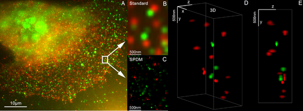
3D super resolution microscopy with standard fluorescent dyes can be achieved by combination of localization microscopy for standard fluorescent dyes SPDMphymod and structured illumination SMI.[49]
There are two basic types of optical microscopes: simple microscopes and compound microscopes. A simple microscope uses the optical power of a single lens or group of lenses for magnification. A compound microscope uses a system of lenses (one set enlarging the image produced by another) to achieve a much higher magnification of an object. The vast majority of modern research microscopes are compound microscopes, while some cheaper commercial digital microscopes are simple single-lens microscopes. Compound microscopes can be further divided into a variety of other types of microscopes, which differ in their optical configurations, cost, and intended purposes.[citation needed]
Iridescence caused by thin-film interference is a commonly observed phenomenon in nature, being found in a variety of plants and animals. One of the first known studies of this phenomenon was conducted by Robert Hooke in 1665. In Micrographia, Hooke postulated that the iridescence in peacock feathers was caused by thin, alternating layers of plate and air. In 1704, Isaac Newton stated in his book, Opticks, that the iridescence in a peacock feather was due to the fact that the transparent layers in the feather were so thin.[5] In 1801, Thomas Young provided the first explanation of constructive and destructive interference. Young's contribution went largely unnoticed until the work of Augustin Fresnel, who helped to establish the wave theory of light in 1816.[6] However, very little explanation could be made of the iridescence until the 1870s, when James Maxwell and Heinrich Hertz helped to explain the electromagnetic nature of light.[5] After the invention of the Fabry–Perot interferometer, in 1899, the mechanisms of thin-film interference could be demonstrated on a larger scale.[6]
The eyepiece, or ocular lens, is a cylinder containing two or more lenses; its function is to bring the image into focus for the eye. The eyepiece is inserted into the top end of the body tube. Eyepieces are interchangeable and many different eyepieces can be inserted with different degrees of magnification. Typical magnification values for eyepieces include 5×, 10× (the most common), 15× and 20×. In some high performance microscopes, the optical configuration of the objective lens and eyepiece are matched to give the best possible optical performance. This occurs most commonly with apochromatic objectives.
Diffraction filmnear me
A compound microscope uses a lens close to the object being viewed to collect light (called the objective lens), which focuses a real image of the object inside the microscope (image 1). That image is then magnified by a second lens or group of lenses (called the eyepiece) that gives the viewer an enlarged inverted virtual image of the object (image 2).[3] The use of a compound objective/eyepiece combination allows for much higher magnification. Common compound microscopes often feature exchangeable objective lenses, allowing the user to quickly adjust the magnification.[3] A compound microscope also enables more advanced illumination setups, such as phase contrast.
Diffractiongratingfilmfor chocolate
The type of interference that occurs when light is reflected from a thin film is dependent upon the wavelength and angle of the incident light, the thickness of the film, the refractive indices of the material on either side of the film, and the index of the film medium. Various possible film configurations and the related equations are explained in more detail in the examples below.
While most techniques focus on increases in lateral resolution there are also some techniques which aim to allow analysis of extremely thin samples. For example, sarfus methods place the thin sample on a contrast-enhancing surface and thereby allows to directly visualize films as thin as 0.3 nanometers.
Using fluorescent samples more techniques are available. Examples include Vertico SMI, near field scanning optical microscopy which uses evanescent waves, and stimulated emission depletion. In 2005, a microscope capable of detecting a single molecule was described as a teaching tool.[39]
Adjustment knobs move the stage up and down with separate adjustment for coarse and fine focusing. The same controls enable the microscope to adjust to specimens of different thickness. In older designs of microscopes, the focus adjustment wheels move the microscope tube up or down relative to the stand and had a fixed stage.
Low-powered digital microscopes, USB microscopes, are also commercially available. These are essentially webcams with a high-powered macro lens and generally do not use transillumination. The camera is attached directly to a computer's USB port to show the images directly on the monitor. They offer modest magnifications (up to about 200×) without the need to use eyepieces and at a very low cost. High-power illumination is usually provided by an LED source or sources adjacent to the camera lens.
All stages move up and down for focus. With a mechanical stage slides move on two horizontal axes for positioning the specimen to examine specimen details.
SMI (spatially modulated illumination microscopy) is a light optical process of the so-called point spread function (PSF) engineering. These are processes which modify the PSF of a microscope in a suitable manner to either increase the optical resolution, to maximize the precision of distance measurements of fluorescent objects that are small relative to the wavelength of the illuminating light, or to extract other structural parameters in the nanometer range.[42][43]
Modern microscopes allow more than just observation of transmitted light image of a sample; there are many techniques which can be used to extract other kinds of data. Most of these require additional equipment in addition to a basic compound microscope.
Many techniques are available which modify the light path to generate an improved contrast image from a sample. Major techniques for generating increased contrast from the sample include cross-polarized light, dark field, phase contrast and differential interference contrast illumination. A recent technique (Sarfus) combines cross-polarized light and specific contrast-enhanced slides for the visualization of nanometric samples.
Thin films are also found in nature. Many animals have a layer of tissue behind the retina, the Tapetum lucidum, that aids in light collecting. The effects of thin-film interference can also be seen in oil slicks and soap bubbles. The reflectance spectrum of a thin-film features distinct oscillations and the extrema of the spectrum can be used to calculate the thickness of the thin-film.[1]
While basic microscope technology and optics have been available for over 400 years it is much more recently that techniques in sample illumination were developed to generate the high quality images seen today.[citation needed]
The object is placed on a stage and may be directly viewed through one or two eyepieces on the microscope. In high-power microscopes, both eyepieces typically show the same image, but with a stereo microscope, slightly different images are used to create a 3-D effect. A camera is typically used to capture the image (micrograph).[citation needed]


 Ms.Cici
 8618319014500