
Curved mirrors - curved mirror
What doesbreast cancer look like on a mammogram
Previously, we covered some of the basics of camera modeling, and examined the pinhole projection model of a camera. There, we looked at some of the historical context behind how affinity in the image plane has been traditionally modeled, and why different models are preferable.
The last kind of distortions to characterize in a calibration are tangential effects, often as a result of de-centered lens assemblies. First, see the following figure for an (exaggerated) example of what these might look like:
Explore HOLOEYE, access job opportunities, discover ongoing projects, stay updated with the latest news, and find out about our upcoming event schedule.
Symmetric radial distortion is an after-effect of our lens not being a perfect pinhole. As light enters the lens outside of the perspective centre it bends towards the image plane. It might be easiest to think of symmetric radial distortion as if we were mapping the image plane to the convexity or concavity of the lens itself. In a perfect pinhole camera, there wouldn't be any distortion, because all light would pass through a single point!
Whatis architecturaldistortionon digital breast tomosynthesis
When an integrated solution like a DOE-based laser projection module is required in your application, HOLOEYE can be part of a joint development effort involving vendors for those products.
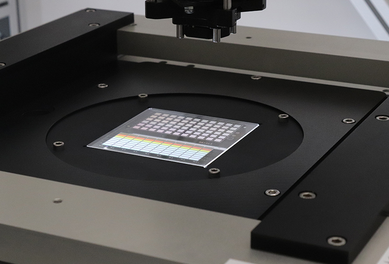
After fabrication, HOLOEYE will validate the compliance of the DOEs with the specification experimentally. For volume production of elements, optical key properties can be monitored using automated equipment.
Architecturaldistortionuncommonly indicates cancer
In the above figure, we represent the image plane as a grid. As we discuss the different kinds of distortions, we'll demonstrate how this grid is warped and transformed. Likewise, for any point \((x, y)\) that we refer to throughout this text, we're referring to the coordinate frame of the image plane, centered (with origin) at the principal point. This makes the math somewhat easier to read, and doesn't require us to worry about column and row offsets \(c_x\) and \(c_y\) when trying to understand the math.
This distortion is characterized as symmetric because it only models distortion as a function of distance from the centre of the image plane. The geometric effect of radial distortion is only in the radial direction, as characterized by \(\delta r\) in the above figure.
right breast architecturaldistortionicd-10
This type of distortion is typically tricky to visualize, as well as to quantify, because it is dependent on the environment. In most robotic and automated vehicle contexts, asymmetric radial distortion is not a great concern! Why? Well, the difference in distortions depends on the difference in distances between objects. This is usually because of some kind of refractive difference between two objects being imaged, or because the objects are out of focus of the camera (i.e. focal length is too large relative to the object distance).
Can an oval breast mass be cancer
Today, we want to explore another part of the camera modeling process: modeling lens distortions. One assumption behind our pinhole-projection model is that light travels in straight rays, and does not bend. Of course, our camera's lens is not a perfect pinhole and light rays will bend and distort due to the lens' shape, or due to refraction. If you've already completed this post, head on over to Part II.
At this point, we've covered the different kinds of lens distortion types one can experience when working with camera-based systems. We'll pause here, and return with Part II, where we'll introduce common distortion models that can be used to correct these distortions, for more accurate calibration models and overall system performance. Read Part II now.
The size and shape of the DOEs can be specified by the costumer. Fresnel-type surface reflections can be reduced by dielectric anti-reflective coatings, or by moth-eye micro-relief surface structures on the otherwise plain substrate surface.
HOLOEYE utilizes its steadily growing experience in the design and simulation of diffractive optical elements to offer its customers a competitive solution. Using in-house developed as well as commercially available state-of-the-art software tools and algorithms, appropriate simulation methods (paraxial or rigorous electromagnetic) are used for optimization of the DOE design.
The different types of DOEs (beam-splitters, pattern generators, kinoforms, beam shapers and gratings) utilize a microstructure surface relief profile for their optical function. Light transmitted by a DOE can be reshaped to almost any desired distribution, just by diffraction and the subsequent propagation. The DOE only encodes the shape of the desired intensity pattern, but maintains other parameters of the incident light source (e.g. beam size, divergence, polarization).
Architecturaldistortionwithnosonographic correlate
Each of these is explored independently below. For each of these distortions, consider the base-case where there is no distortion:
Neither of the above two scenarios are typical; as such, asymmetric radial distortion is an important aspect of modeling the calibration in applications when these scenarios are encountered.
In most robotic contexts, the primary use for imaging and visual-odometry is done in relatively short ranges with cameras that have short focal lengths, and the primary medium for light to travel through is air. Since there doesn't tend to be big atmospheric variances between objects that are close, and since light is all traveling through the same medium, there isn't much of an asymmetric refractive effect to characterize or measure. As a result, this kind of radial distortion isn't common when calibrating cameras for these kinds of applications. If we can't measure it, we shouldn't try to model it!
For requirements beyond the off-the-shelf product range, we offer the development of customized Diffractive Optical Elements using different materials (polymers, fused silica) tailored to your application.
In the above figure, one can see how the lens being either angled with respect to the orthogonal axis of the image plane, or shifted, would project an image into a different spot on the plane. In most cameras used for robotics or automated vehicle applications, tangential distortion will usually be significant enough to model, but is often an order of magnitude smaller than e.g. symmetric radial distortion.
What doesoverlapping breast tissuemean
Due to their design flexibility, DOEs can have optical functions that can otherwise not be achieved at all, or only with complicated optical systems. Moreover, compared to refractive optical elements, DOEs are typically much thinner and lighter, making them an attractive replacement in a number of applications.
The required annual production volume and a price target are helpful in order to balance technical and economical requirements.
Typically when we think of distortion, we try to break down the components into their constituent parts to aid our understanding. However, most lens systems in the real world will have what is often referred to as compound distortion. There's no tricks here, it's simply an aggregate effect of all the previous types of distortions in some combination. This kind of distortion is especially prevalent in cameras with compound lenses, or very complicated lens assemblies.
Fabrication constraints are taken into account right from the start, and a tolerance analysis is performed whenever necessary. Also the alignment requirements of the DOE within the optical system are determined, so that the assembly procedure can be designed accordingly.
The obtained micro-relief profiles serve as fused silica DOEs or templates for UV-curing based replication processes. Alternatively, electroplating can be used to create inverted resist profiles which are usable for embossing and molding processes of polymer materials.
While the two distortions might seem as if they are fundamentally different, they are in fact quite alike! The amount of distortion in the teal lines is greater in magnitude at the edges of our image plane, while being smaller in the middle. This is why the black and teal lines overlap near the centre, but soon diverge as distance increases.

Direct write lithography processes are used to create either lithography masks or resist micro-relief profiles. Based on masks, micro-relief profiles are created by contact or projection lithography and subsequent etching processes like reactive ion etching to transfer the etch mask into the substrate.
Asymmetric radial distortions are radial distortion effects much like the above, but unlike symmetric radial distortion, asymmetric radial distortion characterizes distortion effects that are dependent both on the distance from the image centre as well as how far away the object being imaged is. Asymmetric radial effects are most pronounced in two scenarios:

Tangential distortion is sometimes also called de-centering distortion, because the primary cause is due to the lens assembly not being centered over and parallel to the image plane. The geometric effect from tangential distortion is not purely along the radial axis. Instead, as can be seen in the figure above, it can perform a rotation and skew of the image plane that depends on the radius from the image centre!
What does no distortion at top meanbreast imaging
Before we get into the actual models themselves, it is good to first understand what lens distortion looks like. There are several distinct types of distortions that can occur due to the lens or imaging setup, each with unique profiles. In total, these are typically broken into the following categories:
Symmetric radial distortions are what are typically imagined when discussing image distortion. Often, this type of distortion will be characterized depending on if it is positive (pincushion) or negative (barrel) distortion.


 Ms.Cici
 8618319014500