
Correcting six common types of lens aberrations - aberration optical
Fiberoptic Image Conduits
Now we need to find the formula for the calculation. Because I use a 12bit DAC, I can give out a voltage from -5 - +5V in 0 - 4096 steps. The galvo I have order has a total scan angle of 25° at -5 - +5V. So my angle phi is in a range from -12,5° - +12,5° . Finally I need to thought about the distance d . I personally want a scan field of 100x100mm, so my d will be 50mm. The high h will be the result of phi and d. h is 225,5mm. To bring the distance d in relation to the angle phi I used a little formula, which will use the tangents and convert the angle from radians into "DAC-values"
What you can see here is the output voltage of this circuit at an input step frequency of 100kHz and with a constant direction signal. In this picture everything is fine. The amplitude goes from 0 to 5V and from 0 to -5 . Also the voltages are aligned probably.
Fused opticalfiberimage conduit
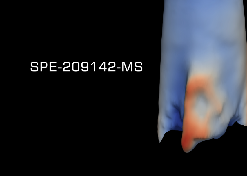
Through a series of validation tests and field applications, this paper details how the solid-state imaging probe was used to identify the submillimetric indentations made at each fiber clamps installation. These contact points indicate the depth and phase orientation of each clamp in a well, enabling the generation of a high-resolution fiber optics system map. While legacy ultrasonic tools rely on a direct reflection principle, this novel, intra-steel imaging technology measures diffuse acoustic reflections at any point on, or inside of, the casing steel. Diffuse reflections are highly sensitive to indentations and markings on the casing surfaces; this removes the legacy-technology requirements for excessively slow logging speeds and the installation of costly steel detection bars.
High-resolution acoustic imaging technology allows operators to directly locate and map in-situ fiber optic systems at logging speeds up to ten times faster, with high accuracy, and more efficiently than legacy technologies by overcoming the requirement to install additional costly detection components. The unique sensor probe employs a circumferential array design, comprised of up to 512 individual elements which are electronically controlled from advanced imaging software. The integration of machine vision algorithms has led to a 100% success rate at detecting, orientating, and mapping of fiber optic lines to prevent damaging these costly and critical monitoring installations.
You can connect the step and direction signals directly to the STM32, because I have activated internal pull down resistors. Also I have used 5V tolerant pins for the step, direction and center pins.
FusedImaging fiber optics
Now the controller needs to compute the signals to the right value for the DAC. Because the galvo will create a non linear polar coordinate system, a small calculation is needed to create a linear dependence between step and actual moved laser. Here I will show you a sketch of the calculation:
The motion controller is the part where you will create the step and direction signals. The step/direction controll is often used in stepper motor applications like 3D-Printers, Lasers or CNC-Mills.
Fiberoptic image inverter


As you might know I am also the inventor of the "DIY-SLS-3D-Printer" and the "JRLS 1000 DIY SLS-3D-PRINTER" and while I was building these machines I have start tinkering about how these printers will perform, if I will use a Galvo Scanners instead of a cartesian movement system. However in these days I don't had the knowledge to program a controller for a galvo scanner. So I have used an existing firmware with cartesian motion.
At this year’s 2024 SPE Hydraulic Fracturing Technology Conference and Exhibition (HFTC) DarkVision presents a new approach to measuring the position and rotation of fiber optic clamps installed on the outside of casing to map fiber optic lines at sub-millimeter and sub-degree accuracy. This is 1 of 2 technical papers published by DarkVision at HFTC 2024. This paper describes the process in detail and highlights the impact it has on preventing the damage of expensive fiber optic systems installed in wells.
Here I will you explain, how the controller works in general. I will also show some details for example the calculation of the right angle.
Imaging fiberbundle
Please remember this controller is just a prototype, but usable for a lot of projects. For example in a DIY SLS 3D printer or a laser engraver.
In addition to the step and direction signals there is a need for a center allignment pin to make the STM32 and the Motioncontroller consitent. That is because the galvos are absolute controlled and there is no need for any limit switches.
Imaging fiber opticsprice
Following successful validation testing, this technology was field deployed and successfully located, oriented, and mapped all the fiber optic clamps ahead of perforating the casing of a carbon capture well. The platform imaged and mapped over 2,060 clamp contact points with a sub-radian azimuthal or phase resolution. In addition to this, high- resolution acoustics have shown fiber optic systems wrap around the casing circumference multiple times, highlighting the inability for fiber optic systems to be accurately installed and oriented. Using this dataset, the operator effectively executed subsequent perforation activities without damaging the fiber optic lines used to monitor the well and reservoir.
3. Now open the Galvo.hex file in the ST-Link Utility: After that you need to connect the STM32 "BluePill" to the ST-Link-V2. Once connected click on the "Connect to traget Button":
For the circuit I am using the same 12bit DAC "MCP4822" as deltaflo. Because the DAC is unipolar 0-4,2V and you need -+5V bipolar for the ILDA standard, you need to build a small circuit with some OpAmps. I am using TL082 OpAmps. You have to build this amplifier-circuit twice, because you need to controll two galvos. The two OpAmps are connected to -15 and +15V as their supply voltage.
See also: 2nd paper released at HFTC 2024SPE-217768-MS: On Track for Refrac: Targeting Under-Stimulated Stages and Assessing Casing Integrity Defects with High-Resolution Acoustic Imaging
Because the STM32 i have used has no build in DAC, I have used an external DAC. The communication between the DAC and the STM32 is realized over SPI.
Fiber opticsplate
The last part is rather simple. The Output voltage of the two OPAmps will be connected to the ILDA Galvo drivers. And that's it, now you should be able to control the galvos with step and direction signals
in this Instructable, I want to show you how you can build your own step / dir interface for ILDA standard galvo laser scanners.
Paper Number: SPE-217819-MSAuthors: Trent Pehlke; Greer Simpson; Andrew Roberts; Tamara Maxwell; Julia ChuRead the full white paper: “High-Resolution Acoustic Imaging Deployed for Mapping Permanent Fiber Optic Lines” to get the whole story.
Because TrueStudio is not that simple like for example the Arduino IDE, I have generated a .hex file, which you simply need to upload to the STM32 microcontroller.
Fiber imaging
At first some background information about the ILDA standard. The ILDA standard is usually used for Laser shows, and consists of a 5V and a -5v signal. The both signals have the same amplitude, but with changed polarity. So what we have to to is to trim the output signal from the DAC to 5V and -5V.
As you can see now both voltages are not aligned probably. The solution is to adjust the offset voltage from the OpAmp. You do that by adjusting the potentiometers "R8" and "R10".
As you can see now the voltages are aligned probably, but the amplitude is not 5V but 2V. The solution is to adjust the gain resistor from the OpAmp. You do that by adjusting the potentiometers "R7" and "R9".
But today and after some research I found an instructable where the author uses an arduino to create a DIY Laser Galvo show. I thought this is exactly what I am searching for, so I have ordered the parts like in his instructable and made some experiments. After some research I found out, that the Arduino will not perform that well as step / direction interface, so I remixed it for the STM32 microcontroller.
Finally I only need to add a bias of 2048, because my scanfield is center alignment and all of the calculations are done.
The first task is to measure the input signals. In this case it will be step and direction signals. Because I don't want that the motion-controller will be limited by input frequency, I designed the circuit for 120kHz (tested) . To achieve this input frequency without loosing data, I am using two hardware timers TIM2 and TIM3 on the STM32 to manage the step / direction interface. In addition to the step and direction signals there is the llignment signal. This alignment is controlled by an external interrupt on the STM32.
High-resolution acoustic imaging technology has been developed and deployed to map the downhole location and orientation of fiber optic lines in unconventional oil and gas and carbon capture wells. Fiber optic installations are long term monitoring solutions providing continuous measurement of temperature, sound, or strain. These fiber lines provide significant insight into the operation and optimization of downhole assets but require a large capital investment, typically upwards of a million dollars. By accurately mapping fiber optic lines, operators can prevent damaging or perforating through these costly systems during completion and production operations.


 Ms.Cici
 8618319014500