
Condensers - condensor lens
Phonecamera sensorsize
The image location and size can also be found by graphical ray tracing, as illustrated in the figures above. A ray drawn from the top of the object to the mirror surface vertex (where the optical axis meets the mirror) will form an angle with the optical axis. The reflected ray has the same angle to the axis, but on the opposite side (See Specular reflection).
Camera sensorsize calculator
Since camera lenses have a fixed AFOV, the Horizontal and Vertical dimensions of the FOV increase with the Working Distance. This means that as WD increases, a larger H x V sample area is mapped onto the H x V dimensions of the image sensor . Magnification is defined as the “scaling factor” in this mapping process from the sample plane to the imager plane:
Boxes 1 and 3 feature summing the angles of a triangle and comparing to π radians (or 180°). Box 2 shows the Maclaurin series of arccos ( − r R ) {\displaystyle \arccos \left(-{\frac {r}{R}}\right)} up to order 1. The derivations of the ray matrices of a convex spherical mirror and a thin lens are very similar.
The mirrors are called "converging mirrors" because they tend to collect light that falls on them, refocusing parallel incoming rays toward a focus. This is because the light is reflected at different angles at different spots on the mirror as the normal to the mirror surface differs at each spot.
The Gaussian mirror equation, also known as the mirror and lens equation, relates the object distance d o {\displaystyle d_{\mathrm {o} }} and image distance d i {\displaystyle d_{\mathrm {i} }} to the focal length f {\displaystyle f} :[2]
For convex mirrors, if one moves the 1 / d o {\displaystyle 1/d_{\mathrm {o} }} term to the right side of the equation to solve for 1 / d i {\displaystyle 1/d_{\mathrm {i} }} , then the result is always a negative number, meaning that the image distance is negative—the image is virtual, located "behind" the mirror. This is consistent with the behavior described above.
Convex mirrors are used in some automated teller machines as a simple and handy security feature, allowing the users to see what is happening behind them. Similar devices are sold to be attached to ordinary computer monitors. Convex mirrors make everything seem smaller but cover a larger area of surveillance.
These mirrors are often found in the hallways of various buildings (commonly known as "hallway safety mirrors"), including hospitals, hotels, schools, stores, and apartment buildings. They are usually mounted on a wall or ceiling where hallways intersect each other, or where they make sharp turns. They are useful for people to look at any obstruction they will face on the next hallway or after the next turn. They are also used on roads, driveways, and alleys to provide safety for road users where there is a lack of visibility, especially at curves and turns.[2]
A concave mirror, or converging mirror, has a reflecting surface that is recessed inward (away from the incident light). Concave mirrors reflect light inward to one focal point. They are used to focus light. Unlike convex mirrors, concave mirrors show different image types depending on the distance between the object and the mirror.
A collimated (parallel) beam of light diverges (spreads out) after reflection from a convex mirror, since the normal to the surface differs at each spot on the mirror.
1/3 vs 1/2.8sensorwhich is better
For concave mirrors, whether the image is virtual or real depends on how large the object distance is compared to the focal length. If the 1 / f {\displaystyle 1/f} term is larger than the 1 / d o {\displaystyle 1/d_{\mathrm {o} }} term, then 1 / d i {\displaystyle 1/d_{\mathrm {i} }} is positive and the image is real. Otherwise, the term is negative and the image is virtual. Again, this validates the behavior described above.
Sensorsize chart
The Lens Specifications Table offers a convenient way to select lenses, filtered by Optical Format and Focal Length. AFOV data is available for the “native” optical format of the lens and also, if available from the manufacturer, for smaller optical formats. Other useful data, such as Optical Resolution, physical dimensions, filter diameter & thread and estimated FOVs for Minimum WD are provided for the lenses.
The image on a convex mirror is always virtual (rays haven't actually passed through the image; their extensions do, like in a regular mirror), diminished (smaller), and upright (not inverted). As the object gets closer to the mirror, the image gets larger, until approximately the size of the object, when it touches the mirror. As the object moves away, the image diminishes in size and gets gradually closer to the focus, until it is reduced to a point in the focus when the object is at an infinite distance. These features make convex mirrors very useful: since everything appears smaller in the mirror, they cover a wider field of view than a normal plane mirror, so useful for looking at cars behind a driver's car on a road, watching a wider area for surveillance, etc.
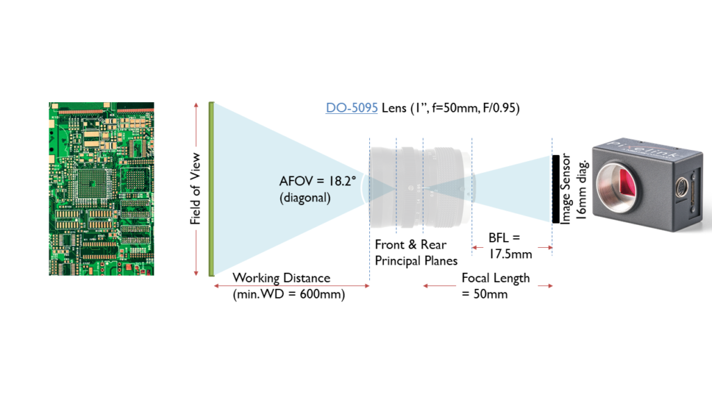
Camera lenses are Fixed Focal Length Lenses, which means that they have a fixed Angular Field of View (AFOV). By setting the focus-adjustment ring on a lens such that a focused image is formed at different working distances, differently sized FOVs can be obtained, since the viewing angle is held constant. AFOV is typically specified as the full angle (in degrees) associated with the horizontal, vertical or diagonal dimension of the sensor with the specified optical format.
Camera sensorsize explained
The sign convention used here is that the focal length is positive for concave mirrors and negative for convex ones, and d o {\displaystyle d_{\mathrm {o} }} and d i {\displaystyle d_{\mathrm {i} }} are positive when the object and image are in front of the mirror, respectively. (They are positive when the object or image is real.)[2]
The passenger-side mirror on a car is typically a convex mirror. In some countries, these are labeled with the safety warning "Objects in mirror are closer than they appear", to warn the driver of the convex mirror's distorting effects on distance perception. Convex mirrors are preferred in vehicles because they give an upright (not inverted), though diminished (smaller), image and because they provide a wider field of view as they are curved outwards.
Even though Optical Formats are specified in inches, for example 4/3″ or 1″, it is best to think of Optical Formats as category names, and not as dimensions! Notice, for example that a 1″ Optical Format corresponds to an image with a nominal diameter of 16mm and not 25.4mm. This has to do with the history of TV cameras and lenses, dating back to the 1960s. In that era, cameras were based on long, cylindrical image-sensor tubes. A standard image-sensor tube with a 1″ diameter yoke had a circular image sensitive area with a 16mm diameter. Since it was expensive to manufacture distortion-free lenses of a larger size than absolutely necessary, lens manufacturers standardized on cost-effective designs described as 1″ format lenses that formed their images on a 16mm diameter circular image-sensitive area.
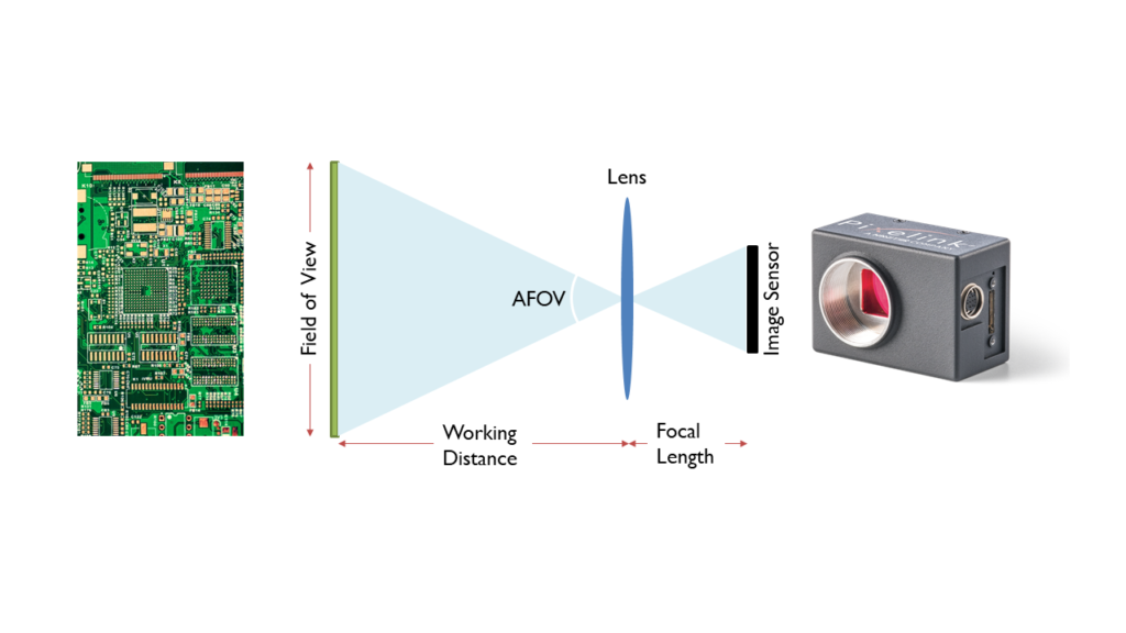
The Field of View (FOV) of a camera and lens is a measure of the spatial dimensions that the camera and lens can include in an acquired image. It is correctly specified in terms of the angle between the two edges of the camera image. In inspection applications, it is common practice to think of a dimensional FOV size – the width, height, or diagonal of the imaging field at a specific distance away from the camera.
Concave mirrors are used in reflecting telescopes.[5] They are also used to provide a magnified image of the face for applying make-up or shaving.[6] In illumination applications, concave mirrors are used to gather light from a small source and direct it outward in a beam as in torches, headlamps and spotlights, or to collect light from a large area and focus it into a small spot, as in concentrated solar power. Concave mirrors are used to form optical cavities, which are important in laser construction. Some dental mirrors use a concave surface to provide a magnified image. The mirror landing aid system of modern aircraft carriers also uses a concave mirror.
1/2.3sensorsize vs 1 inch
The focal length of a lens defines the lens’s AFOV. For a given sensor size, the shorter the focal length, the wider the angular field of view of the lens. All else being the same, a lens with a longer focal length will reduce the FOV, producing an image that appears magnified when displayed. Additionally, the shorter the focal length of the lens, the shorter the distance needed to obtain the same FOV compared to a longer focal length lens.
By convention, if the resulting magnification is positive, the image is upright. If the magnification is negative, the image is inverted (upside down).

The estimated performance of specific camera and lens combinations are shown on this page. Please contact us for assistance in finding the combination that best suits the requirements of your application.
Since larger lenses are typically more expensive, one generally tries to find a lens that is an exact match to the Optical Format of the imager. In the case of an imager for which a matched format lens may not be readily available, it is acceptable to use a lens with an optical format that is slightly higher than that of of the imager. A lens with a larger optical format may be used with an image sensor of a smaller format, although the converse is not true. If the lens area underfills the image sensor area, the corners of the image rectangle may be darkened, as shown in the sketch below. This is an image artifact that is known as “vignetting”.
Most curved mirrors have a spherical profile.[7] These are the simplest to make, and it is the best shape for general-purpose use. Spherical mirrors, however, suffer from spherical aberration—parallel rays reflected from such mirrors do not focus to a single point. For parallel rays, such as those coming from a very distant object, a parabolic reflector can do a better job. Such a mirror can focus incoming parallel rays to a much smaller spot than a spherical mirror can. A toroidal reflector is a form of parabolic reflector which has a different focal distance depending on the angle of the mirror.
Although cylindrical image-sensor tubes have been replaced with rectangular image sensor chips, the naming conventions for the Optical Formats of camera lenses remain a legacy of TV history. 1” optical format lenses are associated with rectangular image sensor with 16mm diagonals; 2/3″ optical format lenses are associated with rectangular image sensor with 11mm diagonals; 1/2″ optical formats are associated with rectangular image sensor with 8mm diagonals, and so on.
A convex mirror or diverging mirror is a curved mirror in which the reflective surface bulges towards the light source.[1] Convex mirrors reflect light outwards, therefore they are not used to focus light. Such mirrors always form a virtual image, since the focal point (F) and the centre of curvature (2F) are both imaginary points "inside" the mirror, that cannot be reached. As a result, images formed by these mirrors cannot be projected on a screen, since the image is inside the mirror. The image is smaller than the object, but gets larger as the object approaches the mirror.
The Working Distance (WD) is specified as the distance from the sample to the front of the lens. Most camera lenses have a specified minimum working distance, which is the minimum distance (between the sample and the front of the lens) at which the lens is capable of forming a focused image.
Round convex mirrors called Oeil de Sorcière (French for "sorcerer's eye") were a popular luxury item from the 15th century onwards, shown in many depictions of interiors from that time.[3] With 15th century technology, it was easier to make a regular curved mirror (from blown glass) than a perfectly flat one. They were also known as "bankers' eyes" due to the fact that their wide field of vision was useful for security. Famous examples in art include the Arnolfini Portrait by Jan van Eyck and the left wing of the Werl Altarpiece by Robert Campin.[4]
Camera sensor formatin inches
Optical Formats are useful in matching lenses to cameras. The goal is to ensure that the circular output image of a lens (shown in light green in the sketch below) is large enough to fully circumscribe the rectangular format of an image sensor, just slightly overfilling the active imaging area.
Camera sensor formatin pixels
A curved mirror is a mirror with a curved reflecting surface. The surface may be either convex (bulging outward) or concave (recessed inward). Most curved mirrors have surfaces that are shaped like part of a sphere, but other shapes are sometimes used in optical devices. The most common non-spherical type are parabolic reflectors, found in optical devices such as reflecting telescopes that need to image distant objects, since spherical mirror systems, like spherical lenses, suffer from spherical aberration. Distorting mirrors are used for entertainment. They have convex and concave regions that produce deliberately distorted images. They also provide highly magnified or highly diminished (smaller) images when the object is placed at certain distances.
Minimum WDs for most lenses are in the range of 100mm~1000mm. As an example, the minimum WD for the DO-5095 lens shown above is specified to be 600mm. The text “0.6m” is stamped on the focus ring indicating that when the focus ring is rotated to this position, the lens is set to its minimum WD=600mm.
Optical Magnification = Sensor Dimension / FOV dimension {this applies to Horizontal, Vertical and Diagonal dimensions. One may also apply the reciprocal of this “scaling factor” when estimating, for example, how the pixel dimensions of the image sensor map to the corresponding dimensions in the sample plane}.
A second ray can be drawn from the top of the object, parallel to the optical axis. This ray is reflected by the mirror and passes through its focal point. The point at which these two rays meet is the image point corresponding to the top of the object. Its distance from the optical axis defines the height of the image, and its location along the axis is the image location. The mirror equation and magnification equation can be derived geometrically by considering these two rays. A ray that goes from the top of the object through the focal point can be considered instead. Such a ray reflects parallel to the optical axis and also passes through the image point corresponding to the top of the object.
The mathematical treatment is done under the paraxial approximation, meaning that under the first approximation a spherical mirror is a parabolic reflector. The ray matrix of a concave spherical mirror is shown here. The C {\displaystyle C} element of the matrix is − 1 f {\displaystyle -{\frac {1}{f}}} , where f {\displaystyle f} is the focal point of the optical device.


 Ms.Cici
 8618319014500