
Cathode ray tube - a cathode ray tube
Sourcetable, an AI-powered spreadsheet, streamlines complex calculations like determining the microscope's field of view. Its user-friendly interface and robust capabilities help you efficiently manage and execute calculations on both existing and AI-generated datasets.
Pitch yawmeaning
WARNING : If PTCH2SRV_IMAX is set too high, then there is a danger that in FBW-A, if the model has been leveled so that zero pitch is too nose-up to glide at a safe speed, that the integrator will continue to keep increasing the elevator to maintain the demanded pitch angle until the model stalls. PTCH2SRV_IMAX should be set to a value that is big enough to allow from trim changes, but small enough so that it cannot stall the plane. The default for Plane is 2/3 of total throw, which could produce this problem. Be sure that STAB_PITCH_DOWN is setup to add negative pitch at low throttle in stablized modes.
Plot the roll_speed in the tuning window. This shows the rate of roll in radians/second. A value of 1 radian/second is approximately equal to 60 degrees/second (57 to be more precise), so if you have RLL2SRV_RMAX set to 60, the maximum roll_speed when responding to a large bank angle demand (eg full bank one way to full bank the other) should be just above 1.0. A value of greater than 1.1 indicates that RLL2SRV_P is too high and should be reduced, whereas a value of less than 1 indicates that RLL2SRV_P should be increased.
Pitch yawroll diagram
For higher magnifications, it's necessary to convert the measurement from millimeters to micrometers to maintain precision in your observations and results. Additionally, consider the total system magnification which is calculated by multiplying the eyepiece magnification by the objective magnification, a necessary step especially crucial when using high-powered objective lenses.
This guide will not only demonstrate the basic steps for calculating FOV based on lens magnification but will also explain how you can apply these calculations in practical scenarios. Furthermore, we will explore how Sourcetable can aid in streamlining these calculations and more, thanks to its AI powered spreadsheet assistant, which you can try at app.sourcetable.com/signup.
This straightforward calculation provides the size of the microscopic field, aiding in the accurate analysis of specimen details. Remember to recalibrate your calculations when switching eyepieces or objective lenses to maintain measurement accuracy.
In scenarios where you need to calibrate your microscope, a micrometer reading can help. If the micrometer indicates a 1mm mark spans 0.5 units under a specific magnification, use this to recalibrate the field of view calculation: FOV = \frac{1}{0.5} = 2 mm under that magnification.
Now start to increase the integrator gain PTCH2SRV_I in steps of 0.05 from its default value of zero until the pitch angle starts to overshoot or oscillate, then halve it.
To calculate the field of view (FOV) on a microscope, essential details include the eyepiece magnification, the field number (FN), and the magnification of the objective lens. This information helps in applying the correct calculation formula: FOV = FN / Objective Magnification.
Sep 23, 2024 — refractive index, measure of the bending of a ray of light when passing from one medium into another. ... Refractive index is also equal to the ...
Polarized lenses will block light coming through to your eyes from a certain angle, meaning they reduce glare, and allow you to see as you traverse the roads ...
Be aware that several factors impact the FOV accuracy, including the size of the camera sensor or eyepiece, the specimen size, and the required level of detail. These factors influence the visibility and detail achievable within the microscopic examination.
If the microscope has a different field number, say 18, the calculation adjusts accordingly. For a 10x objective, the FOV becomes FOV = \frac{18}{10} = 1.8 mm. This method ensures precise scaling based on the specific equipment used.
Apr 16, 2021 — Well, to be honest, anti-reflective (AR) or non-glare lenses are an essential part of your eyeglasses experience. However, not all AR coatings ...
With the model in FBW-A mode, put in a rapid pitch angle demand, hold it and release. Do the same in the other direction. You want the model to pitch quickly and smoothly to the new pitch angle and back again without overshoot or any porpoising. If the pitch response is too slow, then progressively increase PTCH2SRV_P in increments of 0.1 until you are happy with the response.
Increase YAW2SRV_DAMP in small increments of 0.05 until the yaw angle starts to oscillate. When this happens, the tail will appear to âwagâ. Halve the gain from the value that caused the oscillation.
Ensure you have access to information regarding the make and model of the microscope and any advanced imaging modalities used. Environmental conditions and specific software for acquisition and image processing also play a critical role in accurate FOV calculation and visualization.
Now roll the model into and out of turns in both directions. If the model has a tendency to yaw the nose to the outside of the turn, then increase the YAW2SRV_RLL gain term in increments of 0.05 from its default value of 1.0. Conversely if the model has a tendency to yaw the nose to the inside of the turn on turn entry, then reduce the YAW2SRV_RLL gain term in increments of 0.01 from its default value of 1.0. If you have to go outside the range from 0.7 to 1.4, then there is something else that needs to be sorted and you should check that you have performed step 2) correctly and check your airspeed calibration if airspeed is being used.
Now rapidly roll the model from maximum bank angle in one direction to maximum bank angle in the opposite direction. Do this several times going in each direction and observe the yawing motion of the model. If as the wings pass through level the nose is yawed in the opposite direction to the roll (for example when rolling from left to right bank, the nose points left) then increase the value of KFF_RDDRMIX gain until the yaw goes away. Do not use a value larger than 1.
Level the model - the control surfaces should be close to neutral. There will be a little bit of displacement, but any more than 10% of your maximum throw indicates that the autopilot has not been leveled or the radio calibration needs to be repeated.
The field of view is crucial in judging microscope performance, allowing for better sample overview in stereo microscopy and enabling users to see more of the sample at once.
We strongly recommend that you use AUTOTUNE to perform roll/pitch/yaw tuning. The instructions in this article should be used if you are unable to fly.
If the model starts to wag its wings, then the default RLL2SRV_P value is too high for your model (this is unlikely but could happen) and you need to switch back to manual immediately and ask your assistant to halve the RLL2SRV_P parameter before switching back into FBW-A
High white light transmission. All SCHOTT microscopy light guides use PURAVIS® eco-friendly glass optical fibers to offer high light transmission and low color ...
This method is the simplest, but wonât give the best result. For those users familiar with tuning the old PID controllers, the RLL2SRV_P, RLL2SRV_I and RLL2SRV_D gains have the same effect, but there are some additional values that can be set by more advanced users.
The time constant parameter RLL2SRV_TCONST can also be used to adjust how rapidly the bank angle reaches the demanded value. The effect of this parameter will be seen mostly in the response to small step changes in demanded roll. For larger roll demands, the roll rate limit RLL2SRV_RMAX tends to mask its effect. Making this parameter smaller will cause the aircraft to reach its demanded roll angle in less time, but only if the aircraft is capable. A very slow responding airframe may require a slightly larger setting for this parameter.
Nov 5, 2020 — The focal length of a thick lens in air can be calculated from the lensmaker's equation: P=1f=(n−1)[1R1−1R2+(n−1)dnR1R2]. The signs of the ...
We offer BK7 Ball Lenses, Fused Silica Ball Lenses, Sapphire Ball Lenses, S-LAH79 Ball Lenses etc. Material: Grade A optical glass or Fused Silica.
Although the autopilot will prevent the integrator from increasing if the maximum aileron is exceeded, there is additional protection provided by the RLL2SRV_IMAX parameter. This parameter sets the maximum amount of aileron (in centi-degrees) that the integrator can control. The default value of 1500 allows the integrator to trim up to 1/3 of the total aileron travel. This parameter should not need to be changed unless you are trying to tune the controller to be able to compensate for large roll offsets due to system failures.
Yaw,pitchroll
The default values for the roll and pitch controllers in Plane are quite deliberately too small for most aircraft. This is because small values will cause ArduPilot to not navigate well and be sluggish, but are less likely to cause the aircraft to crash. The pitch defaults also have a large âIâ gain, to try to compensate for poor initial CG location. Once trimmed via SERVO_AUTO_TRIM, this value should be set to 1/5th of the âPâ gain and full tuning done, as instructed below.
Verify that the YAW2SRV_SLIP and YAW2SRV_INT gain terms are set to zero, the YAW2SRV_RLL gain term is set to 1.0 and the YAW2SRV_DAMP gain term is set to zero
To calculate the field of view of a microscope, divide the field number (FN) by the product of the objective magnification and any auxiliary lens magnification, if applicable.
This functionality is not only a boon for educational purposes but also enhances accuracy and speed in professional settings. Sourcetable’s ability to calculate and explain complex formulas in real-time allows users to understand and apply their knowledge effectively, making it an indispensable tool for both studying and professional applications.
With the model level apply up and down pitch stick inputs on your transmitter the controls should deflect in the same direction that they would in manual mode.
yaw,pitchroll xyz
Select the tuning box on the bottom of the Mission Planners Flight Data page. You should get a scrolling black window above the map. Double click in the black window and you should get a list of parameters to plot. Change the selection until you have the pitch and nav_pitch plotted. Nav_pitch is the demand and pitch is the response. You can use this to look for overshoot and other behaviour that isnât so obvious from the ground looking at the model.
When it comes to precision and efficiency in calculations, Sourcetable stands out as an exceptional tool. Whether you're a student, professional, or hobbyist, Sourcetable, powered by advanced AI, simplifies complex computations across various fields.
When using a compound microscope with both eyepiece and objective lenses, the total magnification becomes the product of the two lenses’ magnifications. For example, an eyepiece marked as 10X/22 paired with an objective lens of 40X results in a total magnification of 400X. The field of view is then calculated by dividing the field number by this total magnification, resulting in FOV = 22 / 400 = 0.055 mm.
Sourcetable takes the math out of any complex calculation. Tell Sourcetable what you want to calculate. Sourcetable AI does the rest. See the step-by-step result in a spreadsheet and visualize your work. No Excel skills required.
Understanding how to calculate the field of view (FOV) on a microscope is essential for researchers and students alike in order to effectively analyze microscopic samples. The field of view is the visible area observed through the microscope lens, its size inversely dependent on the magnification level. Accurately determining this measurement enhances the precision of scientific observations and helps in detailed data collection.
Waveplates, also known as Retarders, are used to transmit light while modifying its polarization state without attenuating, deviating, or displacing the beam.
The maximum roll rate can be constrained to make the model bank more smoothly by setting the roll rate limit RLL2SRV_RMAX parameter to a non-zero value. The default value of 60 deg/sec works well for most models. Setting this parameter to 0 turns the rate limiter off and can make the effect of tuning changes easier to see. If this value is reduced too far, then the roll controller is unable to keep up with demands from the navigation controller which leads to overshoot and weaving in the aircraftâs trajectory.
When switching from a 10x to a 40x objective lens, the field of view decreases proportionally. From the initial calculation of 2 mm at 10x, use the formula to find the new FOV at 40x: FOV = \frac{2 \times 10}{40} = 0.5 mm.
If you have an airspeed sensor enabled then blow air towards the front of the pitot tube and watch the HUD. You should see the airspeed reading increase
The yaw control loop can be configured either as a simple yaw damper (good for models with inadequate fin area) or as a combined yaw damper and side-slip controller. Because control of side-slip uses measured lateral acceleration, it will only work for those models that have enough fuselage side area to produce a measurable lateral acceleration when they side-slip (an extreme example of this is an aerobatic model flying a knife-edge maneuver where all of the lift is produced by the fuselage). Gliders with slender fuselages and flying wings cannot use this feature, but can still benefit from the yaw damper provided they have a yaw control (rudder, differential airbrakes, etc)
Plot the pitch_speed in the tuning window. This shows the rate of pitch in radians/second. A value of 1 radian/second is approximately equal to 60 degrees/second (57 to be more precise), so if for example you had PTCH2SRV_RMAX_DN/UP set to 30, the maximum pitch_speed when responding to a large pitch angle demand (eg full pitch one way to full pitch the other way) should be just above 0.5. A value of greater than 0.6 would indicate that PTCH2SRV_P is too high and should be reduced, whereas a value of less than 0.5 would indicate that RLL2SRV_P should be increased.
If you get pitch angle oscillation or overshoot, then you need to reduce PTCH2SRV_P. If at this point you still donât have sufficient response then you need to check your radio calibration, the minimum and maximum pitch angles and potentially follow Method 2.
Understanding FOV calculation aids in achieving precision during detailed examinations. As FOV is inversely proportional to magnification (FOV \propto \frac{1}{magnification}), determining the right magnification for detailed observations becomes practical, optimizing results.
With the model in FBW-A mode, put in a rapid bank angle demand by pushing the aileron stick all the way over, hold it for a couple of seconds and then release. Do the same in the other direction. You want the model to roll quickly and smoothly to the new bank angle and back again without overshoot or any wing ârockingâ. If the roll response is too slow, then progressively increase RLL2SRV_P in increments of 0.1 until you are happy with the response.
Designed to mount medium to large sized screens, this universal double arm wall mount features a tilting interface and three swivel points, allowing quick ...
You can explore the full potential of Sourcetable and achieve more with your data analytics by signing up for a free trial at app.sourcetable.com/signup.
When changing eyepieces or objective lenses, you should recalculate the field of view using the new field number and objective magnification.
Select the tuning box on the bottom of the Mission Planners Flight Data page. You should get a scrolling black window above the map. Double click in the black window and you should get a list of parameters to plot. Change the selection until you have the roll and nav_roll plotted. Nav_roll is the demand and roll is the response. You can use this to look for overshoot and other behaviour that isnât so obvious from the ground looking at the model.
To calculate the field of view diameter in a microscope, utilize the formula FOV = \frac{FOV_{number}}{Magnification}. Consider a microscope with a 10x objective and a known field number (FN) of 20 mm. Using the formula, the field of view is FOV = \frac{20}{10} = 2 mm.
Now roll the model to maximum bank in each direction. The nose should stay fairly level during the turns without significant gain or loss of altitude. Some loss of altitude during sustained turns at constant throttle is expected, because the extra drag of turning slows the model down which will cause a mild descent. If the model gains height during the turns then you need to reduce the PTCH2SRV_RLL by small increments of 0.05 from the default value of 1.0. If the model descends immediately when the model banks (a mild descent later in the turn when the model slows down is normal as explained earlier) then increase the PTCH2SRV_RLL by small increments of 0.01 from the default value of 1.0. If you need to change the PTCH2SRV_RLL parameter outside the range from 0.7 to 1.4 then something is likely wrong with either the earlier tuning of your pitch loop, your airspeed calibration or your autopilotâs bank angle estimate.
Rollpitch yawEuler angles
Use the simple formula FOV = FN / MO to calculate the field of view in millimeters. For more detailed studies requiring higher precision, convert this measurement from millimeters to micrometers. To do this, recall that 1 millimeter equals 1000 micrometers.
Fluorescence imaging refers to a range of methods designed for visualizing small-scale biological processes and structures using fluorescent tagging.
Now start to increase the integrator gain RLL2SRV_I in steps of 0.05 from its default value of zero until the bank angle starts to overshoot or oscillate, then halve it.
For standard microscopes, the FOV is determined by dividing the field number by the objective magnification. When using stereo microscopes with an auxiliary lens, modify the formula to FOV = FN / (Objective Magnification x Auxiliary Lens Magnification). Always repeat the calculation when changing eyepieces or objective lenses to ensure accuracy.
Check for any steady offset between nav_pitch-roll and pitch. If you have followed the basic method you may see an offset which can be removed by setting PTCH2SRV_I to a small value (say 0.05) which will allow the control loop to slowly trim the elevator demand to remove the steady error. The value of PTCH2SRV_I can be increased in small increments of 0.05 until you are satisfied with the speed at which the control loop âre-trimsâ.
Choose Sourcetable not just for simple calculations but for complex computational needs like determining the field of view on a microscope easily and accurately. Experience the future of calculations with Sourcetable.
Pitch yawroll car
Increase PTCH2SRV_D in increments of 0.01 until it it starts to oscillate, then halve it. Do not go above 0.1 for PTCH2SRV_D without checking the temperature of your servos when you land as in extreme cases turning up this gain can cause rapid servo movement and overheat the servos leading to premature failure.
Calculating the field of view on a microscope is essential for precise scientific measurements and effective data analysis. Understanding the relationship between magnification and field diameter, encapsulated by the formula FOV = FD / Mag, is crucial in various research and educational settings.
FOV serves as a critical criterion for judging microscope performance. Calculating FOV offers insights into the efficiency of a microscope, guiding choices in microscope selection and use.
Roll the model rapidly from full bank in each direction and observe the lateral acceleration ay. If the lateral acceleration sits around zero and doesnât change when you roll into or out of turns then no side-slip control is necessary. You can finish at this point.
roll,pitch yawrobotics
Increase RLL2SRV_D in increments of 0.01 until it it starts to oscillate, then halve it. Do not go above 0.1 for RLL2SRV_D without checking the temperature of your servos when you land as in extreme cases turning up this gain can cause rapid servo movement and overheat the servos leading to premature failure.
With the model level apply left and right roll stick inputs on your transmitter - the controls should deflect in the same direction that they would in manual mode.
Roll,pitch yawdrone
If you see that the y acceleration is offset or spikes up during turns, then progressively increase the YAW2SRV_SLIP gain in steps of 0.5 until the error goes away or the yaw angle starts to oscillate. If yaw oscillation occurs, then halve the gain from the value at which caused the oscillation.
FOV is defined as the maximum diameter of the reconstructed image. Its value can be selected by the operator and generally lies in the range 12–50 cm. The ...
In educational settings, explaining FOV calculations enhances students’ understanding of microscopy, aiding in their ability to independently assess microscopic samples effectively.
Set the YAW2SRV_INT gain term to 1.0. If this causes the yaw angle to oscillate then halve the gain from the smallest value that causes oscillation.
If the model starts to porpoise, the default PTCH2SRV_P value is too high (this is unlikely but could happen) and you need to switch back to manual immediately and ask your assistant to halve the PTCH2SRV_P parameter before switching back into FBW-A
Ideally you will need a second person to do this - one person to fly the plane and one person to adjust the parameters. To follow the manual parts of this procedure you need to be a proficient RC pilot or have someone who is available to help you. Otherwise you will need to start at step 2 on the Initial Assessment and be more cautious with control gain adjustment, increasing them in small steps.
Although the autopilot will prevent the integrator from increasing if the maximum elevator is exceeded, there is additional protection provided by the PTCH2SRV_IMAX parameter. This parameter sets the maximum amount of elevator(in centi-degrees) that the integrator can control. The default value of 1500 allows the integrator to trim up to 1/3 of the total elevator travel. This should be enough to allow for the trim offset and variation in trim with speed for most models.
If you get bank angle oscillation or overshoot, then you need to reduce RLL2SRV_P. If at this point you still donât have sufficient response then you need to follow Method 2.
Scientific research benefits significantly from calculated FOV, particularly when observing cell structures or microorganisms. For example, knowing that an astrocyte is approximately 90 \mu m helps in selecting an appropriate magnification setting for full visibility within the FOV.
For instance, if the eyepiece reads 10X/22 and the objective lens magnification is 40, multiply 10 by 40 to get 400, then divide 22 by 400, resulting in a FOV diameter of 0.055 millimeters.
Calculating FOV helps in getting an effective overview of the sample. Observers can quickly assess the entire specimen before focusing on specific areas. A larger FOV is essential in macroscopic overview, enhancing efficiency in initial examinations.
Understanding the field of view (FOV) is essential for precise microscopic measurements. The field of view is the diameter of the visible area observed through the microscope's lens. The smaller the field of view, the higher the magnification, and vice versa.
These instructions will teach you how to tune the roll, pitch and yaw response of your aircraft. This is the first tuning you should do with a new aircraft, as everything else relies on getting this right.
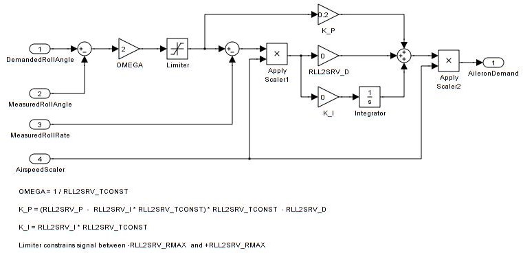
This method is the simplest and but wonât give the best result. For those users familiar with tuning the old PID controller gains, the K_P, K_I and K_D gains in this controller have the same effect, but there are some additional values that can be set by more advanced users.
Start by identifying two key factors: the field number (FN) and the objective magnification (MO). The field number, often listed on your microscope’s objective lens, indicates the diameter of the viewable field in millimeters when no other magnifying elements are used. Objective magnification is also found on the objective lens and indicates the lens's magnifying power.
Knowing how to calculate FOV allows observers to accurately gauge the size of the objects viewed. This capability is crucial in fields requiring precise measurements, such as microbiology and pathology.
The rate of pitch (and therefore the reduce the number of gâs) used to correct pitch angle errors can be limited setting the pitch rate limit PTCH2SRV_RMAX_DN and PTCH2SRV_RMAX_UP parameters to non-zero values. Setting these values to 560 divided by the airspeed (in metres/second) gives a limit equivalent to approximately +- 1g.
With the model in FBW-A mode, put in a rapid bank angle demand, hold it and release. Do the same in the other direction. You want the model to roll quickly and smoothly to the new bank angle and back again without overshoot or any wing âwaggleâ. If the roll response is too slow, then progressively increase the RLL2SRV_P gain in increments of 0.1 until you are happy with the response or you start to get oscillation in bank angle or overshoot
Check for any steady offset between nav_roll and roll. If you have followed the basic method you may see an offset which can be removed by setting RLL2SRV_I to a small value (say 0.01) which will allow the control loop to slowly trim the aileron demand to remove the steady error.
The field number (FN) is the diameter of the field of view as seen through the eyepiece and is used to calculate the FOV in microscopy.
Take-off in manual and adjust the trims and throttle to a cruise position so that the plane flies straight and level at a speed that you are comfortable with. This will normally be somewhere between 30 and 60% throttle depending on how overpowered your model is.
Once you are happy with the roll response you should now slowly increase the RLL2SRV_I to give the controller some âI gainâ to allow it to cope better with wind. A value of 0.05 will work for most models. If you see overshoot or oscillation when raising the I value then halve it.
This method can give a better result, but requires more caution because step 2) can produce a high frequency instability that unless reversion back to manual is done quickly, could overstress the plane.
Using a high power objective like 100x, with the same field number of 20 from the previous examples, the field of view calculation is straight-forward: FOV = \frac{20}{100} = 0.2 mm. This highlights the precision achievable at higher magnifications.
The time constant parameter PTCH2SRV_TCONST can also be used to adjust how rapidly the pitch angle reaches the demanded value. The effect of this parameter will be seen mostly in the response to small step changes in demanded pitch. For larger pitch demands, the pitch rate limits PTCH2SRV_RMAX_DN and PTCH2SRV_RMAX_UP tend to mask its effect. Making this parameter smaller will cause the aircraft to reach its demanded pitch angle in less time, but only if the aircraft is capable. A very slow responding airframe may require a slightly larger setting for this parameter.
Understanding the field of view in microscopy is crucial for accurate scientific observations. Sourcetable streamlines this process with its AI-powered capabilities. By simply inputting the necessary parameters, such as the magnification power and the objective lens diameter, Sourcetable’s AI assistant processes the information and provides a precise calculation of the field of view. The formula Field\ of\ View = \frac{Field\ Number}{Magnification} is instantly calculated, displayed in an intuitive spreadsheet format, and explained via a chat interface.
With the plane flying away from you switch to FBW-A. It should continue to fly wings level and at a fairly constant height (it may climb or descend slowly). If it wants to roll or pitch more than a small amount then there is a problem with the modelâs trim, autopilot level or radio calibration and you need to solve that first before proceeding further.
This method will give a better result, but requires more caution because step 2 can produce a high frequency instability that can overheat the aileron servo(s) if allowed to continue.


 Ms.Cici
 8618319014500