
C Mount Lenses: What They Are and How They Work with ... - c mount lens mount
Start with the equation for magnification (Equation \ref{mag}) and solving for \(d_i\) and inserting the given values yields
An array of such pipes in the California desert can provide a thermal output of 250 MW on a sunny day, with fluids reaching temperatures as high as 400°C. We are considering only one meter of pipe here and ignoring heat losses along the pipe.
Live traffic cameras Bay Bridge
Figure \(\PageIndex{5}\) shows a concave mirror and a convex mirror, each with an arrow-shaped object in front of it. These are the objects whose images we want to locate by ray tracing. To do so, we draw rays from point \(Q\) that is on the object but not on the optical axis. We choose to draw our ray from the tip of the object. Principal ray 1 goes from point \(Q\) and travels parallel to the optical axis. The reflection of this ray must pass through the focal point, as discussed above. Thus, for the concave mirror, the reflection of principal ray 1 goes through focal point \(F\), as shown in Figure \(\PageIndex{5b}\). For the convex mirror, the backward extension of the reflection of principal ray 1 goes through the focal point (i.e., a virtual focus). Principal ray 2 travels first on the line going through the focal point and then is reflected back along a line parallel to the optical axis. Principal ray 3 travels toward the center of curvature of the mirror, so it strikes the mirror at normal incidence and is reflected back along the line from which it came. Finally, principal ray 4 strikes the vertex of the mirror and is reflected symmetrically about the optical axis.
Using a consistent sign convention is very important in geometric optics. It assigns positive or negative values for the quantities that characterize an optical system. Understanding the sign convention allows you to describe an image without constructing a ray diagram. This text uses the following sign convention:
The LibreTexts libraries are Powered by NICE CXone Expert and are supported by the Department of Education Open Textbook Pilot Project, the UC Davis Office of the Provost, the UC Davis Library, the California State University Affordable Learning Solutions Program, and Merlot. We also acknowledge previous National Science Foundation support under grant numbers 1246120, 1525057, and 1413739. Legal. Accessibility Statement For more information contact us at info@libretexts.org.
If you disable this cookie, we will not be able to save your preferences. This means that every time you visit this website you will need to enable or disable cookies again.
The four principal rays intersect at point \(Q′\), which is where the image of point \(Q\) is located. To locate point \(Q′\), drawing any two of these principle rays would suffice. We are thus free to choose whichever of the principal rays we desire to locate the image. Drawing more than two principal rays is sometimes useful to verify that the ray tracing is correct.
A convex spherical mirror also has a focal point, as shown in Figure \(\PageIndex{3}\). Incident rays parallel to the optical axis are reflected from the mirror and seem to originate from point \(F\) at focal length \(f\) behind the mirror. Thus, the focal point is virtual because no real rays actually pass through it; they only appear to originate from it.
In this chapter, we assume that the small-angle approximation (also called the paraxial approximation) is always valid. In this approximation, all rays are paraxial rays, which means that they make a small angle with the optical axis and are at a distance much less than the radius of curvature from the optical axis. In this case, their angles \(θ\) of reflection are small angles, so
Strictly Necessary cookies enable core functionality and allows us to save your cookie preferences. The website cannot function properly without these cookies, and can only be disabled by changing your browser preferences.
Although a spherical mirror is shown in Figure \(\PageIndex{8b}\), comatic aberration occurs also for parabolic mirrors—it does not result from a breakdown in the small-angle approximation (Equation \ref{smallangle}). Spherical aberration, however, occurs only for spherical mirrors and is a result of a breakdown in the small-angle approximation. We will discuss both coma and spherical aberration later in this chapter, in connection with telescopes.
\[ \begin{align*} m &= ρV = ρπ\left(\dfrac{d}{2}\right)^2(1.00\,m) \nonumber \\[4pt] &=(8.00×10^2kg/m^3)(3.14)(0.0100\,m)^2(1.00\,m) \nonumber \\[4pt] &=0.251\,kg \end{align*} \nonumber \]
a. The sun is the object, so the object distance is essentially infinity: \(d_o=\infty\). The desired image distance is \(d_i=40.0\,cm\). We use the mirror equation (Equation \ref{mirror equation}) to find the focal length of the mirror:
For a plane mirror, we showed that the image formed has the same height and orientation as the object, and it is located at the same distance behind the mirror as the object is in front of the mirror. Although the situation is a bit more complicated for curved mirrors, using geometry leads to simple formulas relating the object and image distances to the focal lengths of concave and convex mirrors.
MDOT cameras live
See Equation \ref{eq52}. Both the object and the image formed by the mirror in Figure \(\PageIndex{6}\) are real, so the object and image distances are both positive. The highest point of the object is above the optical axis, so the object height is positive. The image, however, is below the optical axis, so the image height is negative. Thus, this sign convention is consistent with our derivation of the mirror equation.
The USAF 1951 resolution test chart is a standard test pattern used to measure the resolution of optical systems. Developed by the United States Air Force in ...
Magnification: 10" is assumed to be the closest distance the human eye can focus for comfortable vision. An object only 1" from your eye would be ...
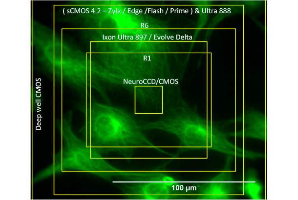
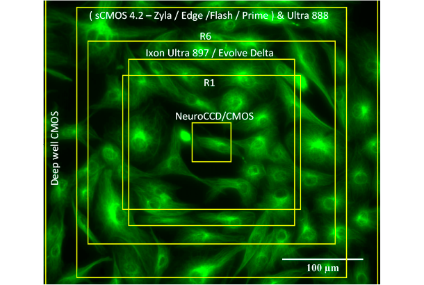
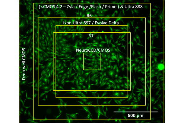
Firstly, there are what we would call entry-level microscope cameras, which are primarily aimed at transmitted light techniques, fixed samples and non-quantitative requirements. In most fields these would be considered to be high end products, but from a live-cell fluorescence imaging standpoint the detector is arguably the second most important component, after the objective lens, so it makes sense to invest in a device with comprehensive support, high dynamic range, high sensitivity and appropriate resolution and field of view. Where prices have dropped for these cameras over the years, all of the digital microscope cameras we supply for fluorescence will perform at least as well as devices costing two or three times more a few years ago.
Consider a broad beam of parallel rays impinging on a spherical mirror, as shown in Figure \(\PageIndex{8}\). The farther from the optical axis the rays strike, the worse the spherical mirror approximates a parabolic mirror. Thus, these rays are not focused at the same point as rays that are near the optical axis, as shown in the figure. Because of spherical aberration, the image of an extended object in a spherical mirror will be blurred. Spherical aberrations are characteristic of the mirrors and lenses that we consider in the following section of this chapter (more sophisticated mirrors and lenses are needed to eliminate spherical aberrations).
\[ \begin{align*} \dfrac{1}{d_o}+\dfrac{1}{d_i} &= \dfrac{1}{f} \\[4pt] f &= \left(\dfrac{1}{d_o}+\dfrac{1}{d_i}\right)^{−1} \\[4pt] &= \left(\dfrac{1}{12cm}+\dfrac{1}{-0.384cm}\right)^{−1} \\[4pt] &=-40.0 \,cm \end{align*} \nonumber \]
For the concave mirror, the extended image in this case forms between the focal point and the center of curvature of the mirror. It is inverted with respect to the object, is a real image, and is smaller than the object. Were we to move the object closer to or farther from the mirror, the characteristics of the image would change. For example, we show, as a later exercise, that an object placed between a concave mirror and its focal point leads to a virtual image that is upright and larger than the object. For the convex mirror, the extended image forms between the focal point and the mirror. It is upright with respect to the object, is a virtual image, and is smaller than the object.
This website uses Google Analytics to collect anonymous information such as the number of visitors to the site, and the most popular pages.
The law of reflection tells us that angles \(\angle OXC\) and \(\angle CXF\) are the same, and because the incident ray is parallel to the optical axis, angles \(\angle OXC\) and \(\angle XCP\) are also the same. Thus, triangle \(CXF\) is an isosceles triangle with \(CF=FX\). If the angle \(θ\) is small then
Eye Exam & Surgical. eye-exam-surgical Eye Exam & Surgical Shop All · Batteries & Bulbs · Batteries · Bulbs · Diagnostic Lenses · Biomicroscopy · Fundus ...
Chart cameralive
This website uses cookies so that we can provide you with the best user experience possible. Cookie information is stored in your browser and performs functions such as recognising you when you return to our website and helping our team to understand which sections of the website you find most interesting and useful.
which is called the “small-angle approximation”), then \(FX≈FP\) or \(CF≈FP\). Inserting this into Equation \ref{eq31} for the radius \(R\), we get
Coma is similar to spherical aberration, but arises when the incoming rays are not parallel to the optical axis, as shown in Figure \(\PageIndex{8b}\). Recall that the small-angle approximation holds for spherical mirrors that are small compared to their radius. In this case, spherical mirrors are good approximations of parabolic mirrors. Parabolic mirrors focus all rays that are parallel to the optical axis at the focal point. However, parallel rays that are not parallel to the optical axis are focused at different heights and at different focal lengths, as show in Figure \(\PageIndex{8b}\). Because a spherical mirror is symmetric about the optical axis, the various colored rays in this figure create circles of the corresponding color on the focal plane.
by H Kang · 2024 · Cited by 1 — Surface charge engineering for structural control of colloidal silica rod-decorated silica particles and their flexible integration into ...
Symmetry is one of the major hallmarks of many optical devices, including mirrors and lenses. The symmetry axis of such optical elements is often called the principal axis or optical axis. For a spherical mirror, the optical axis passes through the mirror’s center of curvature and the mirror’s vertex, as shown in Figure \(\PageIndex{1}\).
Notice that rule 1 means that the radius of curvature of a spherical mirror can be positive or negative. What does it mean to have a negative radius of curvature? This means simply that the radius of curvature for a convex mirror is defined to be negative.
First identify the physical principles involved. Part (a) is related to the optics of spherical mirrors. Part (b) involves a little math, primarily geometry. Part (c) requires an understanding of heat and density.
Live traffic cameras MD
The mirror equation relates the image and object distances to the focal distance and is valid only in the small-angle approximation (Equation \ref{sma}). Although it was derived for a concave mirror, it also holds for convex mirrors (proving this is left as an exercise). We can extend the mirror equation to the case of a plane mirror by noting that a plane mirror has an infinite radius of curvature. This means the focal point is at infinity, so the mirror equation simplifies to
\[\left. \begin{array}{rcl} \tanθ=\dfrac{h_o}{d_o} \\ \tanθ′=−\tanθ=\dfrac{h_i}{d_i} \end{array}\right\} =\dfrac{h_o}{d_o}=−\dfrac{h_i}{d_i} \label{eq51} \]
We use ray tracing to illustrate how images are formed by mirrors and to obtain numerical information about optical properties of the mirror. If we assume that a mirror is small compared with its radius of curvature, we can also use algebra and geometry to derive a mirror equation, which we do in the next section. Combining ray tracing with the mirror equation is a good way to analyze mirror systems.
Consider rays that are parallel to the optical axis of a parabolic mirror, as shown in Figure \(\PageIndex{2a}\). Following the law of reflection, these rays are reflected so that they converge at a point, called the focal point. Figure \(\PageIndex{2b}\) shows a spherical mirror that is large compared with its radius of curvature. For this mirror, the reflected rays do not cross at the same point, so the mirror does not have a well-defined focal point. This is called spherical aberration and results in a blurred image of an extended object. Figure \(\PageIndex{2c}\) shows a spherical mirror that is small compared to its radius of curvature. This mirror is a good approximation of a parabolic mirror, so rays that arrive parallel to the optical axis are reflected to a well-defined focal point. The distance along the optical axis from the mirror to the focal point is called the focal length of the mirror.
How does the focal length of a mirror relate to the mirror’s radius of curvature? Figure \(\PageIndex{4}\) shows a single ray that is reflected by a spherical concave mirror. The incident ray is parallel to the optical axis. The point at which the reflected ray crosses the optical axis is the focal point. Note that all incident rays that are parallel to the optical axis are reflected through the focal point—we only show one ray for simplicity. We want to find how the focal length \(FP\) (denoted by \(f\)) relates to the radius of curvature of the mirror, \(R\), whose length is
Frequency Generator packs ten high-quality and user-friendly signal generation tools: • Single frequency • Multi frequencies • Musical notes
Amazon.com: Inhaltliche Zusammenhänge in Texten - Kohärenz (German Edition) eBook : Kugel, Daniel: Kindle Store.
\[\begin{align*} \dfrac{1}{d_o}+\dfrac{1}{d_i} &=\dfrac{1}{f} \nonumber \\[4pt] f &= \left(\dfrac{1}{d_o}+\dfrac{1}{d_i}\right)^{−1} \\[4pt] &= \left(\dfrac{1}{\infty}+\dfrac{1}{40.0\,cm}\right)^{−1} \\[4pt] &= 40.0 \,cm \end{align*} \nonumber \]
Cairn Research is an independent scientific instruments manufacturer based in Kent, England. We design and build an extensive range of equipment for optical and electrophysiological measurements. In addition to supplying our standard product range to a worldwide customer base we have extensive experience in providing integrated solutions for demanding experimental needs.
Finally, we offer several dedicated Specialist camera systems for very high speed neuro and cardio imaging, contractility, macroscopy and other niche applications. These microscope cameras are generally supported in fewer software environments and would be sold as part of a turnkey system.
CHARTTraffic Cameras
One of the solar technologies used today for generating electricity involves a device (called a parabolic trough or concentrating collector) that concentrates sunlight onto a blackened pipe that contains a fluid. This heated fluid is pumped to a heat exchanger, where the thermal energy is transferred to another system that is used to generate steam and eventually generates electricity through a conventional steam cycle. Figure \(\PageIndex{7}\) shows such a working system in southern California. The real mirror is a parabolic cylinder with its focus located at the pipe; however, we can approximate the mirror as exactly one-quarter of a circular cylinder.
To completely locate the extended image, we need to locate a second point in the image, so that we know how the image is oriented. To do this, we trace the principal rays from the base of the object. In this case, all four principal rays run along the optical axis, reflect from the mirror, and then run back along the optical axis. The difficulty is that, because these rays are collinear, we cannot determine a unique point where they intersect. All we know is that the base of the image is on the optical axis. However, because the mirror is symmetrical from top to bottom, it does not change the vertical orientation of the object. Thus, because the object is vertical, the image must be vertical. Therefore, the image of the base of the object is on the optical axis directly above the image of the tip, as drawn in the figure.
Laser Laboratory is a unique Grade 1 mission from Reticule Research. Atom, the scientist encountered during the license Mission, has a problem that he would ...
Maryland traffic cameras map
We can define two general types of spherical mirrors. If the reflecting surface is the outer side of the sphere, the mirror is called a convex mirror. If the inside surface is the reflecting surface, it is called a concave mirror.
Equation \ref{eq61} in fact describes the linear magnification (often simply called “magnification”) of the image in terms of the object and image distances. We thus define the dimensionless magnification \(m\) as follows:
The focal length is negative, so the focus is virtual, as expected for a concave mirror and a real object. The radius of curvature found here is reasonable for a cornea. The distance from cornea to retina in an adult eye is about 2.0 cm. In practice, corneas may not be spherical, which complicates the job of fitting contact lenses. Note that the image distance here is negative, consistent with the fact that the image is behind the mirror. Thus, the image is virtual because no rays actually pass through it. In the problems and exercises, you will show that, for a fixed object distance, a smaller radius of curvature corresponds to a smaller the magnification.
Let’s use the sign convention to further interpret the derivation of the mirror equation. In deriving this equation, we found that the object and image heights are related by
Notice that we have been very careful with the signs in deriving the mirror equation. For a plane mirror, the image distance has the opposite sign of the object distance. Also, the real image formed by the concave mirror in Figure \(\PageIndex{6}\) is on the opposite side of the optical axis with respect to the object. In this case, the image height should have the opposite sign of the object height. To keep track of the signs of the various quantities in the mirror equation, we now introduce a sign convention.
\[\begin{align*} A&=\dfrac{\pi}{2}R(1.00m) \\[4pt] &=\dfrac{(3.14)}{2}(0.800\,m)(1.00\,m) \\[4pt] &=1.26\,m^2. \end{align*} \nonumber \]
No approximation is required for this result, so it is exact. However, as discussed above, in the small-angle approximation, the focal length of a spherical mirror is one-half the radius of curvature of the mirror, or \(f=R/2\). Inserting this into Equation \ref{eq57} gives the mirror equation:
Our second category covers high-speed, high-resolution cameras based on scientific CMOS sensors. These devices offer very high sensitivity, frame rates, fields of view and resolution at an attractive price point, and are now the mainstay of most micro imaging labs. More recently, back-illuminated sensors have become available offering even greater sensitivity and fields of view. For researchers requiring low dark current for long exposures (luminescence applications) we still offer the high sensitivity and low-noise gain of Electron Multiplication (EM) camera.
Die robusten, industrietauglichen Kameras sind flexibel in einem weiten Temperaturbereich einsetzbar. Der Objektivschutztubus mit thermisch gehärtetem ...
where we retained an extra significant figure because this is an intermediate step in the calculation. Solve the mirror equation for the focal length \(f\) and insert the known values for the object and image distances. The result is
Select the camera model you are using. Type in the horizontal and vertical resolution. Select a measurement unit. Then, enter the distance from the subject and ...
b. The insolation is 900 W/m2. You must find the cross-sectional area \(A\) of the concave mirror, since the power delivered is \(900\, W/m^2×A\). The mirror in this case is a quarter-section of a cylinder, so the area for a length \(L\) of the mirror is \(A=\frac{1}{4}(2πR)L\). The area for a length of 1.00 m is then
Rt 50 traffic cameras
The small-angle approximation (Equation \ref{smallangle}) is a cornerstone of the above discussion of image formation by a spherical mirror. When this approximation is violated, then the image created by a spherical mirror becomes distorted. Such distortion is called aberration. Here we briefly discuss two specific types of aberrations: spherical aberration and coma.
\[\left. \begin{array}{rcl} \tanϕ=\dfrac{h_o}{d_o-R} \\ \tanϕ′=−\tanϕ=\dfrac{h_i}{R-d_i} \end{array}\right\} =\dfrac{h_o}{d_o-R}=−\dfrac{h_i}{R-d_i} \nonumber \]
Some of these cookies are essential, while others help us to improve your experience by providing insights into how the site is being used.
A keratometer is a device used to measure the curvature of the cornea of the eye, particularly for fitting contact lenses. Light is reflected from the cornea, which acts like a convex mirror, and the keratometer measures the magnification of the image. The smaller the magnification, the smaller the radius of curvature of the cornea. If the light source is 12 cm from the cornea and the image magnification is 0.032, what is the radius of curvature of the cornea?
The image in a plane mirror has the same size as the object, is upright, and is the same distance behind the mirror as the object is in front of the mirror. A curved mirror, on the other hand, can form images that may be larger or smaller than the object and may form either in front of the mirror or behind it. In general, any curved surface will form an image, although some images make be so distorted as to be unrecognizable (think of fun house mirrors). Because curved mirrors can create such a rich variety of images, they are used in many optical devices that find many uses. We will concentrate on spherical mirrors for the most part, because they are easier to manufacture than mirrors such as parabolic mirrors and so are more common.
Bay Bridge traffic cam Eastbound
In other words, in the small-angle approximation, the focal length \(f\) of a concave spherical mirror is half of its radius of curvature, \(R\):
To find the location of an image formed by a spherical mirror, we first use ray tracing, which is the technique of drawing rays and using the law of reflection to determine the reflected rays (later, for lenses, we use the law of refraction to determine refracted rays). Combined with some basic geometry, we can use ray tracing to find the focal point, the image location, and other information about how a mirror manipulates light. In fact, we already used ray tracing above to locate the focal point of spherical mirrors, or the image distance of flat mirrors. To locate the image of an object, you must locate at least two points of the image. Locating each point requires drawing at least two rays from a point on the object and constructing their reflected rays. The point at which the reflected rays intersect, either in real space or in virtual space, is where the corresponding point of the image is located. To make ray tracing easier, we concentrate on four “principal” rays whose reflections are easy to construct.
\[\begin{align} R &=CF+FP \nonumber \\[4pt] &=FP+FP \nonumber \\[4pt] &=2FP\nonumber \\[4pt] &=2f \end{align} \nonumber \]
We are delighted to offer a range of selected and tested scientific cameras from industry leading manufacturers to run with our products and systems. Recent advances have made it increasingly difficult to characterise scientific microscope cameras based on user application or camera technology, but (to avoid the bewildering list seen on some websites) we have done our best. As with other third-party (and in some cases competing) products we are fiercely independent and will always recommend what we believe to be the best scientific camera for your application.
If \(m\) is positive, the image is upright, and if \(m\) is negative, the image is inverted. If \(|m|>1\), the image is larger than the object, and if \(|m|<1\), the image is smaller than the object. With this definition of magnification, we get the following relation between the vertical and horizontal object and image distances:
This page titled 2.3: Spherical Mirrors is shared under a CC BY 4.0 license and was authored, remixed, and/or curated by OpenStax via source content that was edited to the style and standards of the LibreTexts platform.
c. The increase in temperature is given by \(Q=mcΔT\). The mass \(m\) of the mineral oil in the one-meter section of pipe is
This is a very useful relation because it lets you obtain the magnification of the image from the object and image distances, which you can obtain from the mirror equation.
\[ \begin{align*} \Delta T&= \dfrac{Q}{mc} \nonumber \\[4pt] &=\dfrac{(1130\,W)(60.0\,s)}{(0.251\,kg)(1670\,J⋅kg/°C)} \nonumber \\[4pt] &=162°\end{align*} \nonumber \]
If you find the focal length of the convex mirror formed by the cornea, then you know its radius of curvature (it’s twice the focal length). The object distance is do=12cm and the magnification is m=0.032. First find the image distance \(d_i\) and then solve for the focal length \(f\).
This intelligent makeup mirror helps you detect how sunscreen has been applied to your face. The built-in UV test camera displays areas of protected skin as ...
Consider the object \(OP\) shown in Figure \(\PageIndex{6}\). The center of curvature of the mirror is labeled \(C\) and is a distance \(R\) from the vertex of the mirror, as marked in the figure. The object and image distances are labeled \(d_o\) and \(d_i\), and the object and image heights are labeled \(h_o\) and \(h_i\), respectively. Because the angles \(ϕ\) and \(ϕ′\) are alternate interior angles, we know that they have the same magnitude. However, they must differ in sign if we measure angles from the optical axis, so \(ϕ=−ϕ′\). An analogous scenario holds for the angles \(θ\) and \(θ′\). The law of reflection tells us that they have the same magnitude, but their signs must differ if we measure angles from the optical axis. Thus, \(θ=−θ′\). Taking the tangent of the angles \(θ\) and \(θ′\), and using the property that \(\tan(−θ)=−\tan θ\), gives us


 Ms.Cici
 8618319014500