
Blaser Rifle Scope Infinity 1-7x28 IC 80400924 - infinity scopes
The coefficients OP1 and OP2 are two different parameters of the Bragg grating spectrum that will change due to the induced elongation or temperature changes. The matrix equation of the temperature and elongation sensor processing will take the form of Equation (8). Taking into account the results obtained from the measurements, it allows us to write the matrix equation in the form below:
The series of high-magnification DIC images presented in Figure 9 illustrate three separate focal planes in the same viewfield of overlapping surface structures present on a typical integrated circuit. In brightfield or darkfield illumination, these structures are often observed merged together and can become quite confusing when attempting to image specific surface details. Figure 9(a) reveals several metal oxide terminals on the upper surface of the integrated circuit, including vias (miniature connections between vertical layers) and part of a bus line. Refocusing the microscope a few tenths of a micrometer deeper exposes numerous connections in the central region of the circuit (Figure 9(b)). Still farther into the circuitry, near the first layers applied above the pure silicon, are a series of metal oxide lines dotted with an ordered array of via connections (Figure 9(c)). The optical sectioning capability of reflected light DIC microscopy is clearly revealed by the ability to image specific focal planes on the surface of this complex integrated circuit.
The graph depicted above shows that the spectral shift calculated as a half wavelength width of FWHM depends on both elongation and temperature. In the case of temperature variations, the transformation of the measured temperature to SSH has a linear character. The temperature sensitivity of the considered monitoring system configuration is associated with a thermal expansion coefficient of the material which the testing plate is made of along with the material of the OTL wire. The shift determined for the different elongation values results directly from the widening of the signal spectrum. As opposed to the SSH parameter, the FWHM spectral width depends only on the elongation of the measurement section and is practically insensitive to the temperature changes. Figure 9 shows the changing characteristics of the FWHM width dependent on the changes of elongation and temperature in the same ranges as in the case shown in Figure 8.
Although reflected light DIC microscopy has been heavily employed for examination of metallographic specimens for the past few years, currently the most widespread and significant application is the examination of semiconductor products as a quality control measure during the fabrication process. In fact, most of the manufacturers now offer microscopes designed exclusively for examination of integrated circuit wafers in DIC, brightfield, and darkfield illumination. DIC imaging enables technicians to accurately examine large volumes of wafers for defects that are not revealed by other microscopy techniques (as illustrated in Figure 4). Minute variations in the geometrical profile of the wafer surface appear in shadowed relief, and maximum image contrast is achieved when the Nomarski prism setting is adjusted to render the background a neutral gray color.
Acting in the capacity of a high numerical aperture, perfectly aligned, and optically corrected illumination condenser, the microscope objective focuses sheared orthogonal wavefronts produced by the Nomarski prism onto the surface of an opaque specimen. Reflected wavefronts, which experience varying optical path differences as a function of specimen surface topography, are gathered by the objective and focused on the interference plane of the Nomarski prism where they are recombined to eliminate shear. After exiting the Nomarski prism, the wavefronts pass through the half-mirror on a straight trajectory, and then encounter the analyzer (a second polarizer) positioned with the transmission axis oriented in a North-South direction. Components of the orthogonal wavefronts that are parallel to the analyzer transmission vector are able to pass through in a common azimuth, and subsequently undergo interference in the plane of the eyepiece fixed diaphragm to generate amplitude fluctuations and form the DIC image. Formation of the final image in differential interference contrast microscopy is the result of interference between two distinct wavefronts that reach the image plane slightly out of phase with each other, and is not a simple algebraic summation of intensities reflected toward the image plane, as is the case with other imaging modes.
By analyzing Equation (23), it could be seen that the simultaneous measurement of the temperature and elongation is possible if, for the proposed monitoring system, we designate two different parameters of the CFBG which show different sensitivities for the measured quantities. It is only possible if the inequality condition OP1 ≠ OP2 is also met, which is fulfilled because FWHMCFBG ≠ SSHCFBG. Analysis of Equation (23) allows us to conclude that with the known (determined experimentally) sensitivities of FWHMCFBG and SSHCFBG for the temperature and elongation, the measured quantities of CSC11, CSC21, CSC12, and CSC22 could be determined simultaneously. The matrix of algebraic complements of all sensor sensitivities CSC11, CSC12 along with CSC21, CSC22 have been calculated using Equation (24) and the received values have been shown in Equation (25):
Secure .gov websites use HTTPS A lock ( Lock Locked padlock icon ) or https:// means you've safely connected to the .gov website. Share sensitive information only on official, secure websites.
When white light from a tungsten-halogen or arc-discharge lamp is used for illumination in reflected light DIC microscopy, the interference fringes associated with topographical changes in the specimen can actually appear in narrow rainbow patterns along the features as the various colors destructively interfere at slightly different locations on the surface. Use of a narrower wavelength band of illumination in specialized applications (for example, light emitted from a laser) will produce a DIC image where the fringes are established by the interference of a single wavelength. These fringes will be sharper and more defined, and their location will not depend upon the spectral response of the detector.
In this article, we have presented a method that monitors the state of an OTL and measures its relative elongation and its actual sag. It is based on the new construction of CFBG sensors and is insensitive to the ambient temperature, the electromagnetic field and any other external typically influencing parameters. Insensitivity has been achieved by the structure of the sensing head that consists of clamps and the special monotonically, non-uniformly extendable steel plate that the CFBG is attached to. The proposed system can be non-invasively and directly embedded on the power line wire. The use of the Bragg grating with a linearly variable period allows for more considerable variation in the optical spectrum than standard FBGs, which translates into an increased sensitivity and accuracy. The obtained sensitivity of the FWHM width to elongation was 0.00603 nm/μm, and at the same time, the FWHM is practically insensitive to temperature changes (sensitivity coefficient reduced to 0.0001 nm/K). This condition allows for the determination of the wire elongation independently of temperature variations. In addition to the determination of the OTL wire extension, the proposed method also allows for the measuring of the temperature around of power line wire by meeting the conditions of the sensitivity matrix equation.
The chirped gratings, compared to conventional FBGs where the period of the refractive index perturbations is constant along the grating length, are characterized by a variable period in the internal structure. Chirps in gratings may take many different forms. The period may vary linearly with the length of the grating, it may be quadratic, and so on. The chirp could also be symmetrical where the period varies by increasing or decreasing around the pitch in the middle of a grating. Generally, modifications applied to the internal structure of the gratings leads to a change of its spectral characteristic. The most widely used CFBGs have a widened spectrum which makes them possible to be used in many areas, including dispersion compensators, mirrors for specialized photonic sensing systems, and sensing elements replacing conventional FBGs. Their widened characteristics allow them to measure not only the wavelength shift, but also the width of the spectra [35]. The proposed method for the power line sag estimation utilizes a simple optomechanical system which allows for the line’s sag change to be converted to the CFBG optical parameter change. The idea of the system is presented in Figure 1. Similar solutions were presented in [17,18] where a sensing head was mounted on an energized power line conductor and the ground voltage was connected directly by fiber-optic cables in the light spectrum processing devices.
A significant difference between differential interference contrast in transmitted and reflected light microscopy is that two Nomarski (or Wollaston) prisms are required for beam shearing and recombination in the former technique, whereas only a single prism is necessary in the reflected light configuration. Light passes through the same Nomarski prism twice, traveling in opposite directions, with reflected light DIC. The shear produced when the light waves pass through the prism on the way to the objective is cancelled during their second journey through the prism upon returning from the specimen surface. In this regard, the Nomarski prism and objective serve an identical function for incoming light waves as the first prism and condenser optical system in a transmitted light microscope. Similarly, light reflected from the specimen surface is gathered by the objective and focused into the Nomarski prism interference plane (conjugate to the objective rear focal plane), analogous to the manner in which these components function in transmitted light.
The idea of the whole optomechanical system is illustrated schematically in Figure 2 and the cross-section is shown in Figure 3. Figure 2b shows the proposed shape of the sensing plate which provides the non-uniform strain while the whole section is extended. The sensing grating was attached to the plate keeping the direction of the chirp shown in the figure below. Grating sections with the most extended periods are placed on the plate segment which is mostly elongated which provides the best response to the spectrum FWHM in the case of wire elongation.
The most popular choice of a light source for reflected light microscopy (including the DIC imaging mode) is the ubiquitous tungsten-halogen lamp, which features a relatively low cost and long lifespan. Incandescent halogen lamps are moderately bright, but require color balancing filters to raise their color temperature to daylight levels for digital imaging and traditional photomicrography with film. An alternative choice, useful at high magnifications and very low bias retardation values (where illumination intensity is critical), is the 75 or 150-watt xenon arc-discharge lamp. Xenon lamps feature a high level of brightness across the entire visible light spectrum, and have color a temperature output that approximates the value required for daylight balance.
Differential interference contrastmicroscopy
The comparison of SSH dependency on (a) the elongation of the testing plate; and (b) the changes of the CFBG sensor surrounding temperature.
A method of measuring the power line wire sag using optical sensors that are insensitive to high electromagnetic fields was proposed. The advantage of this technique is that it is a non-invasive measurement of power line wire elongation using a unique optomechanical system. The proposed method replaces the sag of the power line wire with an extension of the control sample and then an expansion of the attached chirped fiber Bragg grating. This paper presents the results of the first measurements made on real aluminum-conducting steel-reinforced wire, frequently used for power line construction. It has been shown that the proper selection of the CFBG (chirped fiber Bragg grating) transducer and the appropriate choice of optical parameters of such a sensor will allow for high sensitivity of the line wire elongation and sag while reducing the sensitivity to the temperature. It has been shown that with a simple optomechanical system, a non-invasive measurement of the power line wire sag that is insensitive to temperature changes and the influence of high electromagnetic fields can be achieved.
In this case, we will look for the temperature values and maximum stress without knowing the value of matrix M. Let us denote the vector of the searching values as sv. This vector contains the value of the engineering strain e and the temperature T so that we can write:
where CSC11 is the sensitivity of FWHMCFBG to temperature (CSC11 = 0.1 pm/K), CSC21 is the sensitivity of SSHCFBG to the temperature (CSC21 = 22.61 pm/K), CSC12 is the sensitivity of FWHMCFBG to the elongation of testing section (CSC12 = 6.03 pm/μm), and CSC22 is the sensitivity of SSHCFBG to the elongation of the testing section (CSC22 = 4.84 pm/μm).
In the case of chirped Bragg gratings, distinguishing the center wavelength is difficult because of the non-regular character of its spectra. In the processing characteristics shown in this paper, the SSH parameter is calculated based on the half spectral width of the appointed FWHM. Another situation occurs when the wire length changes due to the mechanical elongation which is shown in Figure 7b. The FWHM value sharply increases with the growth of the measured elongation, which promises that in the described measurement system it could be used as a determinant of the power line sag. Figure 8 shows the characteristics of the dependency of SSH on the wire elongation and the surrounding temperature variations in the selected ranges.
where E is the relative elongation coefficient as a measured FWHM function; COP1 is the experimentally evaluated elongation sensor sensitivity coefficient; lref is the reference distance of the installed sensor clamps on the conductor; and Δl is the elongation of the wire segment covered by the sensing head and measured by the CFBG sensor.
Furthermore, the use of chirped fiber Bragg grating with a broad spectrum is advantageous because its spectrum is approximately ten times wider than the usual FBG. The measurements using a CFBG will be more precise than the standard FBG which has a much narrower range. Thus, the proposed system is entirely applicable in a configuration in which the spectra of the grating are interrogated with an optical filter (for example, a filter based on homogeneous FBG). Such a combination can be very interesting because it offers the possibility to eliminate the OSA and use a simple interrogator based on an optical filter.
where CSCij are the complex sensitivity coefficients (i = 1, 2, j = 1, 2). The value ∆l which appears in Equation (8) is the relative elongation length measured between the clamps of sensing head (lref) mounted on the conductor.
The initial conditions shown above are matched for an OTL span right after installing the wire on the poles. Weather conditions cause changes in the elongation of the wire due to icing, ambient temperature, wind speed and angle, and solar radiation. The elongation is also associated with the conductor temperature arising from the electric current flow. As a result of the total wire length L, changes in the power line sag D also vary. In the proposed optomechanical system, the variations of the length of the measured section affect the measured CFBGFWHM spectral width. Characteristics shown in Figure 10 and Figure 11 present how the power line sag will be influenced by the elongation of the testing OTL wire segment and how the FWHM spectral width is affected by sag changes of the power line with the initial parameters described by Equations (21) and (22).
The measurement point fixing system is designed for use for an indefinite time, which is of crucial economic importance. Additionally, such a designed system ensures the stability of its components on the OTL wire without any adverse effect on its strength, mainly due to the non-invasive fixing method. In the case of possible damages to the delicate components of the sensor system, it is possible to replace them with new ones with the same parameters. An important feature is the independence of the measurement from the influence of the outside temperature and the unavoidable electromagnetic field at the measurement site.
Super resolutionmicroscopy
World-class Nikon objectives, including renowned CFI60 infinity optics, deliver brilliant images of breathtaking sharpness and clarity, from ultra-low to the highest magnifications.
Articles from Sensors (Basel, Switzerland) are provided here courtesy of Multidisciplinary Digital Publishing Institute (MDPI)
A schematic cutaway diagram of the key optical train components in a reflected light differential interference contrast microscope is presented in Figure 1. Illumination generated by the light source passes through the aperture and field diaphragms (not illustrated) in a vertical (episcopic) illuminator before encountering a linear polarizer positioned with the transmission axis oriented East-West with respect to the microscope frame. Linearly polarized light exiting the polarizer is reflected from the surface of a half-mirror placed at a 45-degree angle to the incident beam. The deflected light waves, which are now traveling along the microscope optical axis, enter a Nomarski prism housed above the objective in the microscope nosepiece where they are separated into polarized orthogonal components and sheared according to the geometry of the birefringent prism.
(a) The dependency of the OTL wire sag related with the elongation of the proposed measurement system plate calculated for the initial conditions described in Equations (21) and (22); and (b) the dependency of the measured FWHM for different sag values of the monitored OTL line.
dic显微镜
In reflected light microscopy, the vertical illuminator aperture diaphragm plays a major role in defining image contrast and resolution. Reducing the aperture size increases the apparent depth of field and overall image sharpness while simultaneously producing enhanced contrast. However, if the diaphragm is closed too far, diffraction artifacts become apparent, image intensity is significantly reduced, and resolution is sacrificed. Often, the optimum aperture diaphragm setting is a compromise between accurately rendering specimen detail in sufficient contrast and retaining the resolution necessary to image minute features, while at the same time avoiding diffraction artifacts.
An essential feature of both reflected and transmitted light differential interference contrast microscopy is that both of the sheared orthogonal wavefront components either pass through or reflect from the specimen, separated by only fractions of a micrometer (the shear distance), which is much less than the resolution of the objective. To the observer, it is not apparent that the resulting image visualized in the eyepieces is composed of these two superimposed components, because their separation is too minute to be resolved by the microscope. However, each point in the image is derived from two closely spaced and overlapping Airy disks originating from adjacent points on the specimen, and each disk has an intensity that corresponds to its respective optical path difference induced by the specimen. Image contrast is described as being differential because it is a function of the optical path gradient across the specimen surface, with steeper gradients producing greater contrast.
An alternative mechanism for introduction of bias retardation into the reflected light DIC microscope optical system is to couple a de Sénarmont compensator in the vertical illuminator with fixed-position Nomarski prisms (illustrated in Figures 5(c), 5(d), and 6) for the objectives. In the de Sénarmont configuration, each objective is equipped with an individual Nomarski prism designed specifically with a shear distance to match the numerical aperture of that objective. The prisms are glued into frames and housed in a dust-tight assembly that mounts between the objective and the microscope nosepiece (Figure 5(d)). Objectives are threaded into the Nomarski prism housing, which is then secured to the nosepiece. A small lever is used to shift the prism frame into and out of the optical pathway (the prism positionlever in Figure 5(d)). Because of the increased number of Nomarski prisms required for the de Sénarmont DIC microscope configuration, these accessories are considerably more expensive than the sliding prism in a traditional reflected light Nomarski DIC microscope.
The light from the light source (SLED) was directed to the CFBG sensor via an optical circulator. The optical spectrum reflected from the elongated CFBG was returned through the optical circulator to the optical spectrum analyzer (OSA). Thermal expansion and additional mechanical loads on the OTL wire cause variations in the length of the measured wire section surrounded by attached clamps as shown in Figure 2. In such cases, the response of the single-mode fiber with the inscribed CFBG results in the widening of the spectral characteristics which is caused by the nonlinearity of the strain applied to the transducer.
When compared to the typical configuration employed in transmitted light microscopy, the critical instrument parameters for reflected (or episcopic) light differential interference contrast (DIC) are much simpler, primarily because only a single birefringent Nomarski or Wollaston prism is required, and the objective serves as both the condenser and image-forming optical system. Because of the dual role played by the microscope objective, a Nomarski prism interference pattern projected into the objective rear focal plane is simultaneously positioned at the focal plane of the condenser illuminating lens system.
Reflected light microscopy is one of the most common techniques applied in the examination of opaque specimens that are usually highly reflective and, therefore, do not absorb or transmit a significant amount of the incident light. Slopes, valleys, and other discontinuities on the surface of the specimen create optical path differences, which are transformed by reflected light DIC microscopy into amplitude or intensity variations that reveal a topographical profile. Unlike the situation with transmitted light and semi-transparent phase specimens, the image created in reflected light DIC can often be interpreted as a true three-dimensional representation of the surface geometry, provided a clear distinction can be realized between raised and lowered regions in the specimen.
The characteristics of the FWHM spectral width dependency on (a) the relative elongation; and (b) the ambient temperature of the proposed system.
Official websites use .gov A .gov website belongs to an official government organization in the United States.
After the polarized light waves reach the half-mirror and are deflected, the remainder of the microscope optical train operates in a manner similar to that of a traditional DIC reflected light microscope. Thus, on the downward journey through the reflected light microscope, linearly polarized light first encounters the fixed Nomarski prism and is sheared according to the geometry of the prism wedges. After being focused by the objective lens elements and projected onto the opaque specimen, light is reflected back into the objective where it converges at the rear focal plane (coincident with the Nomarski prism interference plane). Sheared wavefronts are recombined at the prism interference plane and proceed to the analyzer, where components that are parallel to the transmission azimuth are passed on to the intermediate image plane. At the image plane, constructive and destructive interference occurs between wavefronts emerging from the analyzer to generate the DIC image.
This paper introduces a direct method for calculation of the sag D based on a single spot conductor elongation measurement with a CFBG sensor. Assuming that the horizontal tension H and conductor thermal elongation is constant over the span, the relative elongation measurement Δl of the selected 10 cm wire segment covered with the sensing head clamps provides the data required for the calculation of the total wire length L, as described with Equations (17)–(20). According to previous considerations, the relative wire elongation Δl could be appointed as a function of the sensor FWHM spectral width as shown below:
differential interference contrast中文
Microscopes equipped with a single translatable Nomarski prism in the nosepiece require only a polarizer and an analyzer as accompanying components in order to operate in differential interference contrast imaging mode. The polarizer is usually mounted together with a rack-and-pinion or planetary gearset into a thin rectangular frame, so that the transmission azimuth can be rotated through 360 degrees with a thumbwheel. The polarizer frame is introduced into the light path between the field diaphragm and the half-mirror through a slot in the vertical illuminator. Likewise, the analyzer can also be housed in a frame that enables rotation of the transmission axis. Analyzer frames are usually placed into a slot in the nosepiece or near the tube lens in the upper portion of the vertical illuminator. In some cases, either the analyzer or polarizer is mounted in a fixed frame that does not allow rotation, but most microscopes provide the operator with the ability to rotate the transmission azimuth of at least one of the polarizers in order to compensate for opaque specimens that absorb light. Housing the polarizer and analyzer in slider frames enables the operator to conveniently remove them from the light path for other imaging modes. When the polarizers remain in place and the Nomarski prism slider is removed, the microscope is configured for observation in polarized reflected light mode.
where FWHMCFBG is the full-width at half maximum of the CFBG spectrum and SSHCFBG denotes its spectral shift. Equation (1) can be written in the matrix form as follows:
where SCij (i = 1–2, j = 1–2) is the sensitivity coefficients that are defining the optical parameters sensitivity of the CFBG sensor OPi on the temperature T along with the elongation Δl. Let us denote the matrix of coefficients SC as:
Fiber Bragg grating (FBG) sensors can be used to measure many physical quantities, such as strain, stress, elongation, temperature [1], and refractive index [2]. The advantage of optical method based research is the lack of influence on the tested object, the ability to perform non-invasive measurements which can be performed in a wide variety of fields such as mechanical structures diagnostics or even medicine [3]. Among the FBG structures are some significant gratings in which the period is not uniform [4]. Many studies have been published demonstrating the promising properties of periodic structures with non-uniform periods, especially chirped fiber Bragg gratings [5]. These structures can be used for separated parameter monitoring [6], independent strain and temperature measurement [5,7,8], dispersion compensation [9,10], or structural health monitoring [11]. Tapered fibers with CFBG have significantly improved strain sensitivity [12]. The CFBG sensors can also be used with inexpensive interrogators [13] and their specially-designed structures can be used as optical filters [14,15,16]. The loads of the overhead power transmission lines can be measured using a few uniform FBGs. In some embodiments, each grating is bonded directly to the conductor with epoxy [17], which makes it difficult to disassemble when the sensor head cracks. There are also known systems for distributed monitoring of overhead transmission lines with fiber Bragg grating sensor networks [18]. Such systems are very promising because they can be used to provide multiple types of information for smart grids. FBG sensors can be fairly used to monitor the strain of transmission line wire. In this case, the strain of the conductor is directly proportional to the ampacity of the cable [19]. In such systems, the strain of the grating cannot be widely adjusted because the optical fiber extends equally with the power line conductor. In this paper, the authors would like to present the construction of sensing heads where the CFBG is attached to the so-called control sample steel plate whose dimensional adjustment allows for the control of the sensitivity and measuring range. Among the various methods of constructing these periodic structure based sensors, this is the first method proposed to the best of our knowledge in which the CFBG can be implemented with the strain and sag of power lines can be measured using a special optomechanical system and the control specimen. Today, modern power systems and smart grids are required to have the operational flexibility of electrical power transmission whilst preserving the appropriate safety margin [20,21]. In the context of overhead transmission lines (OTL), the above approach can be implemented by dynamic line rating (DLR) systems [22,23,24,25]. The DLR systems allow for the continuous monitoring of operating conditions and the electromechanical state of the OTL span [20,26] or of the whole line [27]. The most important parameters determining the safe operation of the OTL, among others, are the sag and strain of the wire, which are direct functions of its actual temperature resulting from a load of electric current and atmospheric conditions [28,29,30]. The unquestionable advantages of fiber-optic and FBG sensors are the insensitivity of the measurement to the strong electromagnetic field, the speed of measurement, the non-invasive installation of the sensor on the conductor, the small power demand for the supply of the measuring system, and not needed a complex sensor or radio [31]. At present, the dynamic development of the FBG based monitoring systems is observed [32,33]. Using OTL monitoring and its actual state [28], the current wire elongation sag is a critical parameter in determining the distance from the ground or obstacle [34] that is affecting the operational safety.
As discussed above, reflected light DIC images are inherently bestowed with a pronounced azimuthal effect, which is the result of asymmetrical orientation of the beamsplitting Nomarski prism with respect to the microscope optical axis and the polarizers. The result is that many opaque specimens imaged in differential interference contrast have a prerequisite orientation limitation in order to achieve maximum contrast (either parallel or perpendicular to the shear axis) that restricts freedom of specimen rotation. This is especially critical with highly ordered semiconductors having numerous extended, linear regions intermixed with closely-spaced periodic structures.
It is also worth mentioning that the design of the sensing head protects the optical fiber because changing the wire length within the possible elongation range does not damage the optical fiber. Additionally, the mass of the sensing head is negligible relative to the mass of the entire wire in the span so the sensor does not affect the object being measured. Figure 11 shows the dependency of the calculated sag of the power line with the assumed initial parameters on the measured FWHM spectral width. The potential of the method is increased by the use of a chirped fiber Bragg grating CFBG whose spectral characteristics are broader (more extensive) than in the case of a conventional FBG.
Azimuth contrast effects in reflected light differential interference contrast can be utilized to advantage by equipping the microscope with a 360-degree rotating circular stage. An essential element in polarized light microscopy, circular stages enable the operator to rotate the specimen with respect to the shear axis in order to maximize or minimize contrast effects for selected specimen features. Contrast in reflected light DIC microscopy achieves a minimum level for linear phase specimens that extend along the direction of shear, but can be varied significantly by rotating the stage by 90 degrees. Non-linear metallurgical specimens, such as mosaic grain boundaries, wires, amorphous alloys, and crystalline spherulites, do not display significant azimuthal effects in reflected light DIC, and can usually be imaged satisfactorily in a variety of orientations.
The shape of a catenary is a function of the conductor weight per unit length weight w, the horizontal component of tension H, span length S, and the maximum sag of the conductor D. The exact catenary equation uses hyperbolic functions, as shown in Equation (9). The right side of the Equation (9) is an approximation of the hyperbolic cosine using the Maclaurin series expansion:
If the spectral response of the CFBG/FBG were to be measured using an interrogator (for example, based on an FBG optical filter) and not using an OSA, the measurement would be more accurate since the measured spectra would be broader and changes in its width would be measured more accurately by the interrogator.
The optical train of a reflected light DIC microscope equipped with de Sénarmont compensation is presented in Figure 6. Light from the illumination source is focused by the collector lens and passes through the aperture and field diaphragms before encountering a linear polarizer in the vertical illuminator. Positioned directly behind the polarizer in the optical pathway is a quarter-wavelength retardation plate fixed into position where the fast axis is oriented East-West with respect to the microscope frame. Together, the polarizer and retardation plate comprise the de Sénarmont compensator (Figure 5(c)). When the polarizer transmission azimuth is aligned parallel to the fast axis of the retardation plate in the de Sénarmont compensator, linearly polarized light emerges from the assembly, and is deflected at a 90-degree angle by the vertical illuminator half-mirror into the pathway of imaging elements in the microscope.
where index 1 and 2 are the beginning and end states, respectively; L1, L2: the conductor length in the span; T1, T2 are the conductor temperature; αAS is the thermal elongation coefficient for ACSR; σ1, σ2 are the conductor stress; and β and the wire elastic elongation coefficient.
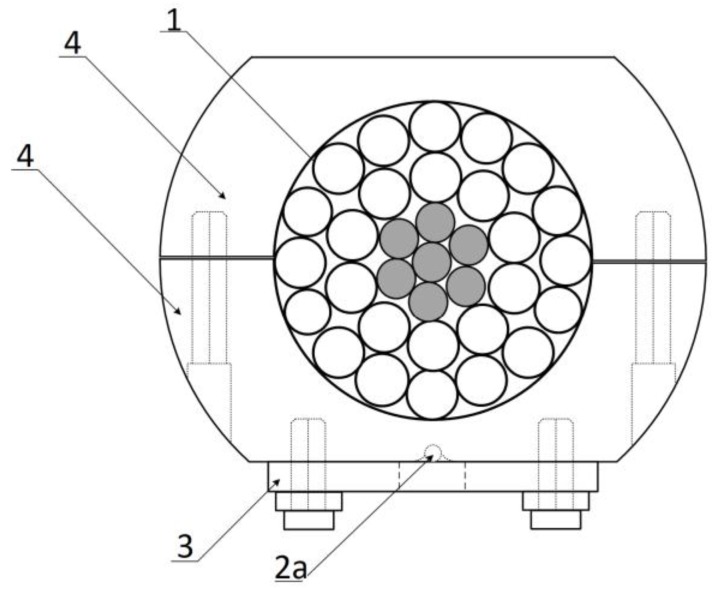
The cross-section of the sensing head of the power line sag measurement system where: 1, 2a, 3, and 4 are elements equivalent to those shown in Figure 2.
Because the components for differential interference contrast must be precisely matched to the optical system, retrofitting an existing reflected light microscope, which was not originally designed for DIC, is an undesirable approach. Instead, all of the major microscope manufacturers now offer industrial and research-grade microscopes equipped with vertical illuminators and the necessary auxiliary optical components (usually marketed in kits) to outfit a microscope for DIC observation. Several different approaches to instrument design have yielded two alternatives for the introduction of bias retardation into the differential interference contrast microscope optical system.
The parabolic approximation is sufficiently accurate as long as the sag in the span does not exceed 5% of its length [36]. The power line sag D varies with the conductor temperature, ice, wind loading, and time as the conductor creeps. The horizontal tension H is equal to the conductor tension in the middle of the span shown in Figure 4. At the endpoints where the wire is fixed to the insulators, the conductor tension F is equal to the horizontal tension H plus the conductor weight per unit length w multiplied by the sag D, according to Equation (11) [36]:
In modern microscopes, the distance between the objective focal plane and the seating face on the nosepiece is a constant value, often referred to as the parfocal distance. Therefore, a single Nomarski prism can often be mounted at a fixed distance from the objective seats (and rear focal planes) on the nosepiece in a slider frame, and service the entire magnification range with regards to beam shearing and recombination duties. In some cases, especially at the higher magnifications, variations in the position of the objective rear focal plane can be accommodated by axial translation of the Nomarski prism within the slider (illustrated in Figures 5(a) and 5(b)). This is often accomplished with a knob or lever that relocates the entire prism assembly up and down along the microscope optical axis. Reflected light microscopes that utilize a single prism for DIC are able to introduce bias retardation by laterally translating the prism across the microscope optical axis with a thumbwheel. The entire Nomarski prism slider can be removed from the optical path when the microscope is used for other imaging modes (brightfield, polarized light, darkfield, and fluorescence).
The conductor sag D can be calculated as a function of Δl, according to the reference conductor length Lref. The overhead transmission line conductor’s sag-tension calculations are typically based on the catenary equation, which describes an entirely flexible rope rigidly fixed at both ends. The catenary equation is defined using hyperbolic sine or cosine functions. However, it can be reliably approximated by a parabola. The main difference between a catenary equation and the parabolic approximation is that catenary assumes a constant weight per unit length through the conductor while the parabolic equation assumes an invariable weight per unit horizontal length. This simplification causes the sag calculation with the parabolic approximation to be smaller than when it is estimated with the catenary equation.
Modern vertical illuminators designed for multiple imaging applications usually include a condensing lens system to collimate and control light from the source. In addition, these illuminators contain an aperture iris diaphragm and a pre-focused, centerable field diaphragm to enable the microscope to operate in Köhler illumination (Figure 3). Vertical illuminators also have numerous slots and openings for insertion of light balancing and neutral density filters, polarizers, compensators, and fluorescence filter combinations housed in cube-shaped frames. When configured to operate with infinity-corrected objectives, vertical illuminators are equipped with a tube lens (see Figure 1) to focus light waves into the intermediate image plane. Both tungsten-halogen and arc-discharge lamphouses can be utilized with vertical illuminators (often interchangeably) to provide a wide range of illumination intensity and spectral characteristics.
According to Equations (14) and (19), it is shown that for OTL wire sag calculation is enough to measure an elongation of a particular section of the wire.
It should be noted that all determined sensitivity coefficients and final results are also dependent on the geometry of the transducer and the initial parameters of the CFBG sensor together with the control plate. Future work will involve an investigation into a sensitivity analysis for the function of changes of the parameters mentioned above and on the metrological conditions of the whole system.
Chris Brandmaier - Industrial Microscope Division, Nikon Instruments, Inc., 1300 Walt Whitman Road, Melville, New York 11747.
The fulfilled condition of the various sensitivity ratios of FWHMCFBG and SSHCFBG for the temperature and elongation gives the possibility of simultaneous determination of both quantities by measuring the spectrum shift (SSHCFBG) and the spectral width of the CFBG characteristic (FWHMCFBG).
The matrix M has 2 × 2 dimensions, is symmetrical for all vectors x∈ℝ2, and is real. As a result of the measurements, the sensitivity matrix M is determined and the vector of searching values sv can be calculated based on the measured magnitude vector mv. Measuring the optical parameters of the CFBG, such as FWHMCFBG and SSHCFBG allows for the determination of the fiber temperature T and elongation ∆l according to the matrix equation below:
Illustrated in Figure 8 are three specimens imaged in reflected light DIC with a full-wave retardation plate inserted behind the de Sénarmont compensator in a fixed-prism microscope configuration. Figure 8(a) reveals surface defects in a high-temperature superconducting ceramic single crystal grown from an amorphous flux at 950 degrees Celsius. Although twinning defects in the crystal are difficult to discern without applying optical staining techniques, these crystalline mishaps become quite evident and are manifested by significant interference color fluctuations when the retardation plate is installed. Similarly, adhesion failure in a magnetic thin film is clearly imaged when optical staining techniques are employed in reflected light DIC (Figure 8(b)). Separation points in the film are imaged as wrinkles that appear in spectacular relief, surrounded by interference fringes, when observed in white light. Finally, bus line details stand out in sharp color contrast on the surface of the integrated circuit presented in Figure 8(c). A wide spectrum of differential color effects are possible with integrated circuits in reflected light DIC microscopy, based on a number of factors, including the presence or absence of silicon nitride or polyimide protective coatings, phase relationships between fabrication materials, and the feature linewidth of the fabrication process.
On most reflected light microscopes, the field diaphragm can be centered in the optical pathway by partially closing the iris aperture and translating the entire diaphragm via a set of centering screws (or knobs) adjacent to the aperture opening control lever. In practice, the field diaphragm should be opened until it is just outside the viewfield or the area to be captured on film or in a digital image. The primary purpose of the field diaphragm is to control the size of the field of view and to prevent stray light from obscuring specimen details. In conjunction with the field diaphragm, the aperture diaphragm determines the illumination cone geometry and, therefore, the angle of light striking the specimen from all azimuths. The iris diaphragm size can be modulated to adjust specimen contrast, and generally should be set to a size that is between 60 and 80 percent of the objective rear aperture. Such a setting provides the best compromise between maximum resolution and acceptable contrast.
All microscope designs that employ a vertical illuminator for reflected light observation suffer from the problem of stray light generated by the reflections from the illuminator at the surface of optical elements in the system. In particular, the upper and lower planar surfaces of the Nomarski prism can be problematic in producing annoying reflections that create excessive glare and degrade image quality. To counter this effect, Nomarski prisms designed for reflected light microscopy are fabricated so that the interference plane is positioned at an angle with respect to the shear axis of the prism (see Figure 2(b)). When the interference plane of the specialized Nomarski prism is brought into coincidence with the objective rear focal plane (perpendicular to the microscope optical axis) by its positioning inside the sliding frame or fixed housing, the flat outer wedge surfaces are now inclined with respect axial illumination pathway (Figures 1, 2(b), and 5(a)). As a result, reflections are diverted away from the half-mirror, specimen, eyepieces, and camera system so as not to adversely affect image intensity and contrast.
The system shown in Figure 1 allows for the elongation and sag measurement of the OTL wire. The light source was a superluminescent light emitting diode (SLED). The Thorlabs S5FC1005S (Thorlabs, Newton, NJ, USA) was attached to a single-mode optical fiber used as a transmission light-guide. The light emitted from the SLED source illuminated the sensing CFBG with a 1 nm/cm chirp, inscribed on the hydrogen-loaded SMF-28 part at the end of the fiber. The optical fiber with the CFBG sensor was connected/glued to a thinned plate which was 1 mm in thickness and made of steel (1.0037 S235JR UNI according to the norm EN 10025). The shape of the control plate is shown in Figure 2. The plate is screwed to the semi-circular clamps fixing the control plate with the CFBG sensor to an OTL wire (Figure 2). The elongation of the OTL wire causes the clamps to move apart and increase the tension of the control plate, which is monotonically extending the length of its measuring section with the CFBG attached.
(a) the optomechanical system using a chirped fiber Bragg grating and a mechanical strain transformer where: 1: the ACSR 26/7 (Hawk) conductor; 2a: the optical fiber; 2b: the chirped fiber Bragg grating; 3: the thinned steel plate; 4: the semi-circular screwed clamps, lref: reference sensing head length; and (b) the strain distribution in the proposed steel testing plate while extending the measurement section.
For a flat span, the low point is at the center and the wire sag D is found by substituting x = S/2. Exact and approximate formulas for the sag calculations is shown in Equation (10):
The overhead transmission line wire sag measurement system where: 1: the ACSR 26/7 Hawk conductor; 2: the measuring clamps/sensing head; 3a: the optical fiber; 3b: the inscribed chirped fiber Bragg grating; 4: the light source with a stabilized super-luminescent diode; 5: the optical circulator; 6: the optical spectrum analyzer; and 7: the computer/gateway.
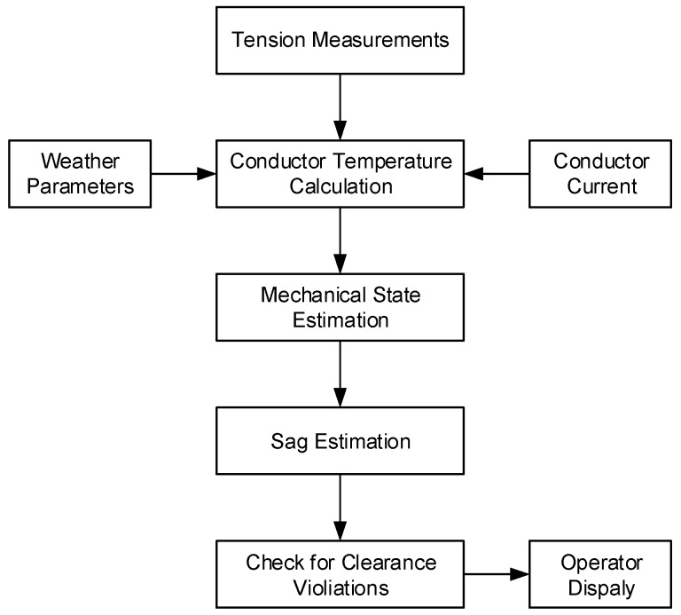
where S is the span length; σ1, σ2 = H/A is the wire stress; g = w/A is volumetric weight; A is the wire cross-sectional area; and β = 1/γ is the wire elastic elongation coefficient. For ACSR 26/7 Hawk conductors, typically α = 18.7 × 10⁻⁶ 1/K, γ = 75,000 MPa, A = 276.2 mm2, w = 9.52 N/m, and g = 34.47 N/(m·mm2) [37]. In such cases, we need to measure tension, stress, or the wire temperature to estimate the total length of the wire in the span and then calculate sag. Sometimes, a calculation of the bare conductor temperature can be done using the methods presented in [28,29,30] based on weather parameters, electric current, or conductor tension measurements. The algorithm for conductor sag calculation was investigated by [26] and is presented in Figure 5.
Michael W. Davidson - National High Magnetic Field Laboratory, 1800 East Paul Dirac Dr., The Florida State University, Tallahassee, Florida, 32310.
The vertical illuminator is a key component in all forms of reflected light microscopy, including brightfield, darkfield, polarized light, fluorescence, and differential interference contrast. A reflected light (often termed coaxial, or on-axis) illuminator can be added to a majority of the universal research-level microscope stands offered by the manufacturers. Reflected light DIC can be performed using the Nikon LV100N POL upright microscope. The primary function of a vertical illuminator is to produce and direct semi-coherent and collimated light waves to the rear aperture of the microscope objective and, subsequently, onto the surface of a specimen. Reflected light waves gathered by the objective then travel a pathway similar to the one utilized in most transmitted light microscopes. A critical component of the vertical illuminator is a partially reflecting plane glass mirror (referred to as a half-mirror; see Figure 3) that deflects light traveling from the horizontal illuminator by 90 degrees into the vertical optical train of imaging components in the microscope. The half-mirror, which is oriented at a 45-degree angle with respect to both the illuminator and microscope optical axis, also allows light traveling upward from the objective to pass through undeviated to the eyepieces and camera system.
The proposed method has a low cross-sensitivity, as seen in the final matrix of the processing system in Equation (25). An analytical determination of the OTL sag was proposed based on the CFBG spectra measurements mounted directly on the Hawk wire using the special semicircular screwed clamps forming the whole sensing head. Empirical studies have confirmed the low cross-sensitivity values (CSC11 = 0.1 pm/K, CSC21 = 22.61 pm/K, CSC12 = 6.03 pm/μm and CSC22 = 4.84 pm/μm). We have shown that such use of CFBGs and the suitable optomechanical system allows for the monitoring of the relative wire elongation and the OTL sag D. The presented method is non-sensitive to temperature changes (the FWHM width used for the determination of elongation is practically insensitive to thermal variations), provides repeatability of measurements (by the mechanical construction of clamps and the whole sensing head) and it is non-invasive .
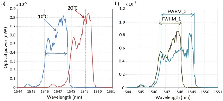
The influence of temperature variations on the measurement system described above was measured for a short segment of the power line wire with the mounted complete system (clamps, steel plate with attached optical fiber). The OTL wire segment was placed in a climate-control chamber with a temperature range established at 10–90 °C. Figure 7a shows the spectral characteristics of the CFBG reflected signal measured for border cases of the surrounding temperature: 10 °C and 90 °C. The increase of the surrounding temperature of the wire changes the CFBG spectral characteristic by shifting the whole spectrum to longer wavelengths. The spectrum is not widened so the FWHM parameter of the sensor output characteristics has a quasi-constant character. However, the shift of the spectrum could be distinguished and measured and in this paper is called SSH (spectral shift).
The correlation between image contrast and specimen orientation in reflected light DIC microscopy can often be utilized to advantage in the investigation of extended linear structures (especially in semiconductor inspection). By capturing images at several orientations, DIC microscopy is often able to present a clear representation of the complex morphology present in many extended, linear specimens. In addition, when optical sectioning methodology is coupled to azimuth-specific imaging, reflected light DIC microscopy can often reveal features that are difficult, or impossible, to distinguish using alternative techniques.
Because the interference plane in a conventional Wollaston prism is positioned in the central portion of the prism, at approximately the centerline between the two quartz wedges, it is difficult to adapt this prism design for use with standard microscope objectives in reflected light DIC microscopy. This problem arises because the interference plane of the prism must coincide and overlap with the rear focal plane of the objective, which often lies below the thread mount inside a glass lens element. On the other hand, external displacement of the interference plane in Nomarski prisms renders them ideal for use with microscope objectives since they can be positioned some distance away (for example, in the nosepiece) and still establish a conjugate relationship between the objective rear focal plane and the compound prism interference plane. In a reflected light DIC microscope, the Nomarski prism is oriented so that the interference plane is perpendicular to the optical axis of the microscope (as is the objective rear focal plane).
In reflected light DIC microscopy, the optical path difference produced by an opaque specimen is dependent upon the topographical geometrical profile (surface relief) of the specimen and the phase retardation that results from reflection of sheared and deformed orthogonal wavefronts by the surface. For a majority of the specimens imaged with DIC, the surface relief varies only within a relatively narrow range of limits (usually measured in nanometers or micrometers), so these specimens can be considered to be essentially flat with shallow optical path gradients that vary in magnitude across the extended surface. Phase changes occurring at reflection boundaries present in the specimen also produce and optical path difference that leads to increased contrast in the DIC image. These phase differentials are more likely to be found at junctions between different media, such as grain boundaries and phase transitions in metals and alloys, or aluminum and metal oxide regions in a semiconductor integrated circuit.
By the condition of the non-zero matrix determinant of Equation (24), it is possible to construct its complementary matrix based on Equation (24), which we will now write in the form:
Several mask alignment markers are illustrated in the image of a semiconductor surface presented in Figure 7(c). One of the markers has been placed on a metallic bonding pad, while the other rests on a smooth metal oxide surface. Both markers contain eight lines, equally spaced at 45-degree intervals, and having the same length. Note that the lines oriented parallel to the shear axis are very dark for the marker resting on the metal oxide surface, while the upper left line on the bonding pad marker is almost invisible. The marker lines oriented perpendicular (northeast to southwest) to the shear axis are much brighter and far more visible than lines having other orientations, although the lines parallel and perpendicular to the image boundaries are clearly visible.
Dark fieldmicroscopy
It is common to perform sag-tension calculations using only the horizontal tension component H, but the average of the horizontal and support point tension F is usually shown. The conductor length in the span can be calculated with the application of a catenary equation using Equation (12). The right side of Equation (12) corresponds to a parabolic approximation of the catenary function:
The optical parameter OP1 denotes the full-width at half maximum (FWHM) of the measured CFBG spectrum, while the OP2 parameter reflects the spectral shift (SSH). Thus, it can be assumed that OP1 and OP2 depend upon the relative elongation Δl and temperature T (Equations (3) and (4)):
Optical staining is accomplished either through translation of the Nomarski prism across the optical pathway by a significant distance from maximum extinction, or by inserting a full-wave compensator behind the quarter-wavelength retardation plate in a de Sénarmont configuration. A full range of interference colors can be observed in specimen details when the Nomarski prism is translated to extreme ranges, or the polarizer is rotated with de Sénarmont compensation coupled to a full-wave plate. With the compensator in place, the background appears magenta in color, while image contrast is displayed in the first-order yellow and second-order blue colors of the Newtonian interference color spectrum. Under these conditions, small variations in bias retardation obtained by translation of the Nomarski prism (or rotating the polarizer in a de Sénarmont compensator) yield rapid changes to interference colors observed in structures having both large and small surface relief and reflection phase gradients.
The shadow-cast orientation is present in almost every image produced by reflected light DIC microscopy after bias retardation has been introduced into the optical system. In addition, the direction of optical shear is obvious and can be defined as the axis connecting regions of the image displaying the highest and lowest intensity values. Surface features become distinguishable because shadow directions are often reversed for specimen details that posses either a higher or lower topographical profile than the surrounding surface. Because the shear axis is fixed by Nomarski prism design and other constrains involved in wavefront orientation for reflected light DIC microscopy, the axis direction cannot be altered to affect specimen contrast through a simple setting on the microscope. However, the relative phase retardation between sheared wavefronts can be reversed by relocating the Nomarski prism from one side of the microscope optical axis to the other (shifting the bias retardation value from negative to positive, or vice versa). The same maneuver can be accomplished by rotating the polarizer to the corresponding negative value on a de Sénarmont compensator. When phase retardation is altered as just described, the orientation of bright and dark edges in the image is reversed by 180 degrees.
Primary candidates for observation in reflected light DIC microscopy include a wide variety of metallographic specimens, minerals, alloys, metals, semiconductors, glasses, polymers, and composites. The high resolution afforded by the technique has been employed to ascertain specimen details only a few nanometers in size. For example, spiral growth dislocation patterns in silicon carbide crystals that are only about 30-40 nanometers high can be imaged in high relief, while thin films approximately 200 nanometers thick have been successfully observed in monochromatic yellow sodium light. Phase transitions and recrystallization processes can be examined in reflected light DIC, as well as minute details on the surface of glasses and polymers.
The typically temperature-tension calculation of the power line span is performed using Equation (16) [36] and solved using iterative methods:
Differential interference contrast
The ability to capitalize on large objective numerical aperture values in reflected light DIC microscopy enables the creation of optical sections from a focused image that are remarkably shallow. Without the confusing and distracting intensity fluctuations from bright regions occurring in optical planes removed from the focal point, the technique yields sharp images that are neatly sliced from a complex three-dimensional opaque specimen having significant surface relief. This property is often employed to obtain crisp optical sections of individual features on the surface of integrated circuits with minimal interference from obscuring structures above and below the focal plane.
Nomarski and Wollaston prisms not only separate linearly polarized light into two orthogonal components, they also produce a relative phase shift (often termed an optical path difference) in each wavefront relative to the other. The degree of phase shift between the wavefronts varies linearly with the location of the input light beam in relation to the shear direction. Thus, the prism can be laterally translated along the optical axis of the microscope in the shear direction (a process known as introduction of bias retardation) to enable adjustment of the optical path difference introduced between the orthogonal wave components. In this manner, fine-tuning of the relative intensity in the image can be manipulated to produce the distinctive shadow-cast appearance for which DIC microscopy is so well known. Images appear as if they were illuminated from a highly oblique light source originating from a single azimuth.
Bias retardation between the sheared wavefronts in reflected light DIC microscopy can be manipulated through the use of compensating plates, such as a first-order (often termed a full-wave or first-order red) plate having a retardation value equal to a full wavelength in the green region (550 nanometers) of the visible light spectrum. Compensating plates bestow greater control for adjusting the contrast of specimen details in relation to the background intensity and color values, and also enable more precise tuning of the bias value between orthogonal wavefronts. These birefringent components are also frequently employed for optical staining of opaque specimens, which are normally rendered over a limited range of grayscale values.
Confocalmicroscopy
The traditional method for establishing reflected light DIC is to employ a Nomarski prism attached to a mobile carriage within a rectangular frame (often termed a slider) that fits into the microscope nosepiece base, above the revolving objective turret (Figures 5(a) and 5(b)). In this design, bias retardation is introduced by rotating a thumbwheel positioned at the end of the slider that, in turn, translates the Nomarski prism back and forth laterally across the microscope optical axis. An alternative technique, termed de Sénarmont compensation (see Figure 6), utilizes individual fixed prisms for each objective (Figure 5(d)), and a quarter-wavelength retardation plate in combination with the linear polarizer (Figure 5(c)) to introduce an optical path difference (bias retardation) between orthogonal wavefronts.
Licensee MDPI, Basel, Switzerland. This article is an open access article distributed under the terms and conditions of the Creative Commons Attribution (CC BY) license (http://creativecommons.org/licenses/by/4.0/).
The ordinary and extraordinary wavefronts proceeding to the specimen through a Nomarski prism experience optical path differences that have a magnitude dependent upon the location of the wave as it enters the prism. After the wavefronts exit the prism, they enter the objective lens system (acting as an illumination condenser) from the rear, and are focused into a parallel trajectory before being projected onto the specimen. Reflection of the orthogonal wavefronts from a horizontal, opaque specimen returns them to the objective, but on the opposite side of the front lens and at an equal distance from the optical axis (see Figure 2(b)). The waves gathered by the objective are focused on the Nomarski prism interference plane (again on the opposite side from their journey down), which results in a phase shift that exactly offsets the original difference produced before the waves entered the objective. As a result, the positional exchange of incident and reflected waves results in cancellation of relative phase shifts across the entire microscope aperture. A system of this type is referred to as being self-compensating, and the image produced has a uniform intensity. Compensation of the reflected light DIC system can be compared to that for transmitted light, where two matched, but inverted, Nomarski (or Wollaston) prisms are used to shear and recombine the beam. In the transmitted light configuration, the condenser prism (often termed the compensating prism) is imaged onto the objective prism (referred to as the principal prism) so that optical path differences are matched at every point along the surface of the prisms. Thus, in the transmitted light configuration, the principal and compensating prisms are separate, while the principal prism in reflected light DIC microscopy also serves the function of the compensating prism.
The surveys were performed on a real overhead power transmission line. The measurement system was mounted directly on a 110 kV OTL power line wire which was energized. The proper construction of the optomechanical system, provided its compact size and weight, makes it negligible to the mechanical workings of the power line. Figure 6 shows a photograph of the measurement system mounted on an ACSR 26/7 Hawk wire.
The optical pathway, both for the entire wavefront field and a single off-axis light ray, in reflected light DIC microscopy are illustrated in Figures 2(a) and 2(b), respectively. In each case, linearly polarized light from the polarizer is deflected by the half-mirror and enters the Nomarski prism located behind the objective. Sheared wavefronts are focused by the objective lens system and bathe the specimen with illumination that is reflected in the form of a distorted wavefront (Figure 2(a)) or the profile of an opaque gradient (Figure 2(b)) back into the objective front lens. The optical path difference produced between orthogonal wavefronts enables some of the recombined light to pass through the analyzer to form a DIC image. In Figure 2(b), note that the trajectory of the light ray incident on the specimen is displaced by the same distance from the microscope optical axis as the ray reflected from the surface.
Keywords: power system monitoring, power lines sag measurement, chirped fiber Bragg gratings, quasi-periodic waveguide structures, strain measurement, elongation measurement
Light waves employed for reflected DIC microscopy must be at least moderately collimated in order to provide uniform compensation across the full beamwidth for the two required passes through the prism, and to insure that phase differences introduced by slopes and reflection boundaries in the specimen can be detected. Because the phase difference experienced by a beam on its first pass through the prism is governed by the pathway, accurate compensation of the reflected beam requires passage along a complimentary portion of the prism. In order to ensure collimation of the light beam, the microscope must be properly configured for Köhler illumination to guarantee that input waves are parallel (or nearly so) to the optical axis. A poorly collimated input beam will result in nonuniform compensation across the prism (and the resulting image), and destroys the unique phase relationship between orthogonal components at each image point.
This work was realized with the collaboration of all authors. Michal Wydra, Piotr Kisala and Piotr Kacejko contributed to the idea of this work. Michal Wydra, Piotr Kisala and Damian Harasim conceived and designed the experiments; Damian Harasim and Michal Wydra performed the experiments; Piotr Kisala, Michal Wydra and Damian Harasim analyzed the data. Michal Wydra wrote the biggest part of the article and contributed all the work referred to the transmission lines and sag-tension calculations using presented optomechanical measuring system designed by Piotr Kisala. Mechanical simulations and all the optical part of the manuscript was contributed by Piotr Kisala and Damian Harasim. Piotr Kacejko provided the funding. All the authors contributed to the production of the paper, the discussion of the results and the reviewing process of the intellectual content of the article and finally approved the manuscript.
(a) a comparison of the spectra measured for the CFBG mounted in the proposed OTL wire monitoring system for 10 °C and 90 °C surrounding temperatures; (b) a comparison of the spectra measured for CFBG: FWHM_1 refers to the measurement directly after mounting the system on the wire and FWHM_2 refers to the measurement after 0.1% relative elongation.
Polarizationmicroscopy
Köhler illumination in reflected light microscopy relies on two variable diaphragms positioned within the vertical illuminator. The basic system is configured so that an image of the lamp filament is brought into focus at the plane of the aperture diaphragm, which is conjugate to the rear focal plane of the objective (where the filament can also be observed simultaneously in focus). A field diaphragm, employed to determine the width of the illumination beam, is positioned in the same conjugate plane as the specimen and the fixed diaphragm of the eyepiece. The aperture iris diaphragm is closer to the light source, while the field diaphragm is closer to the objective (the opposite configuration from that employed for transmitted illumination). Differential interference contrast is particularly dependent upon Köhler illumination to ensure that the waves traversing the Nomarski prism are collimated and evenly dispersed across the microscope aperture to produce a high level of contrast.
An angular splitting or shear of the orthogonal wavefronts occurs at the boundary between cemented quartz wedges in a Wollaston prism, and the waves become spatially separated by an angle defined as the shear angle. At this boundary, the ordinary and extraordinary waves also exchange identities and diverge away from each other as a function of the refractive index experienced by each wave as it travels through the quartz prism. The shear angle and separation distance is constant for all incident wavefronts across the face of the prism, regardless of the entry point. The direction of wavefront shear is defined by the prism shear axis, which lies in the plane of the Wollaston prism and is parallel to the optical axis of the lower quartz wedge section. In a Nomarski prism, the wedge having an oblique optical axis produces wavefront shear at the quartz-air interface, and is responsible for defining the shear axis.
The difference between the conductor length L and span length S is defined as the conductor slack. Equation (14) shows that small changes in the slack give significant changes in the conductor sag. As it was mentioned above, conductor sag depends mainly on the total conductor length L when the span length S remains constant. The temperature dependency of the conductor length L is typically calculated using Equation (15):
Bias retardation is introduced into the reflected light de Sénarmont DIC system simply by rotating the linear polarizer in the vertical illuminator. By rotating the polarizer transmission azimuth with respect to the fast axis of the retardation plate, elliptically and circularly polarized light having an optical path difference between the orthogonal wavefronts is produced. When the polarizer axis is rotated up to 45 degrees in one direction, right-handed elliptical or circular polarizer light emerges from the de Sénarmont compensator. Rotating the polarizer in the opposite direction produces elliptical or circular wavefronts having a left-handed rotational sense. The optical path difference introduced by rotating the polarizer (over a range of plus or minus one-half wavelength) is further compounded when the orthogonal wavefronts enter the Nomarski prism and are sheared across the face of the prism. Introducing an optical path difference at the de Sénarmont compensator is analogous to the effect achieved when the objective Nomarski prism is translated across the optical path in a traditional DIC microscope configuration.
Although optical staining is also possible in transmitted light DIC, the effect is far more useful with reflected light techniques, especially when examining flat, planar specimens, such as integrated circuits that have surface relief variations restricted to relatively narrow limits. In contrast to the transparent specimens imaged with transmitted light, surface relief in opaque specimens is equivalent to geometrical thickness. In addition, localized differences in phase retardation upon reflection of incident light from an opaque surface can be compared to the refractive index variations experienced with transmitted light specimens. For many applications in reflected light DIC, specimen details are frequently superimposed on a homogeneous phase background, a factor that dramatically benefits from contrast enhancement through optical staining (interference) techniques. With the thin transparent specimens that are optimal for imaging with transmitted light DIC, the range within which optical staining can be effectively utilized is considerably smaller (limited to a few fractions of a wavelength), rendering this technique useful only for thicker specimens.
Although largely a tool restricted to industrial applications, reflected light differential interference contrast microscopy is a powerful technique that has now been firmly established in the semiconductor manufacturing arena. The millions of computer chip components fabricated each year rely heavily on reflected light DIC to ensure quality control and help prevent failure of the circuits once they have been installed. Because of the countless hours spent by technicians examining integrated circuits, microscope manufacturers are now carefully turning their attention to ergonomic considerations in the design of new reflected light instruments. The result will undoubtedly be highly refined microscopes that produce excellent DIC images, while minimizing the discomfort and neuro-muscular disorders experienced by operators who must spend long periods repetitively examining identical specimens.
The Wollaston and Nomarski prisms employed in reflected light DIC microscopy are fabricated in the same manner as those intended for use with transmitted light instruments. The single birefringent prism for reflected light is comprised of two precisely ground and polished wedge-shaped slabs of optical quartz that are identical in shape, but have differing orientations of the optical axes. In a Wollaston prism, the quartz wedges are cemented together at the hypotenuse with an orientation that positions the optical axes perpendicular to each other. Conversely, in a Nomarski prism, the axis of one wedge is parallel to the flat surface, while the axis of the other wedge is oriented obliquely. As a result of geometrical constraints, the interference plane for a Wollaston prism lies near the center of the junction between the quartz wedges (inside the compound prism), but the Nomarski prism interference plane is positioned at a remote location in space, outside the prism itself. Incident linearly-polarized light waves (parallel to the optical axis of the microscope) that enter a Wollaston or Nomarski prism are divided into two mutually perpendicular (orthogonal) components, termed the ordinary and extraordinary wave, which have identical amplitudes (70.7 percent of the original polarized wave) and are coherent (provided, of course, that the illumination source is also coherent). In order to produce orthogonal components having equal amplitudes, the linearly polarized light entering a Nomarski or Wollaston prism is oriented with the electric vector vibration direction positioned at a 45-degree angle with respect to the principal optical axis in the upper wedge of the prism.
Illustrated in Figure 4 are images of the region near a bonding wire pad on the surface of a microprocessor integrated circuit captured in brightfield, darkfield, and differential interference contrast illumination using a vertical illuminator and reflected light. The brightfield image (Figure 4(a)) suffers from a significant lack of contrast in the circuit details, but provides a general outline of the overall features present on the surface. Darkfield illumination (Figure 4(b)) reveals only slightly more detail than brightfield, but does expose discontinuities near the vertical bus lines (central right-hand side of the image) and the bonding pad edges on the left. The differential interference contrast image (Figure 4(c)) yields a more complete analysis of the surface structure, including the particulate bonding pad texture, connections from the bonding pad to the bus lines, and numerous fine details in the circuitry on the left-hand side of the image.
The full-width half-maximum (FWHM) comparison of the spectral characteristics of the signals reflected from the Bragg sensor with the value assigned to the reference length of the segment gives information on the current elongation of the OTL wire. At the same time, changes in the wire surrounding temperature cause spectral shifts to the whole CFBG spectrum and do not affect the FWHM. The linear relationship between the elongation of the conductor, its temperature, and its stress allow for the determination of the elongation value. In the case of this sensor, the matrix equation of the processing can be written as:
When the Nomarski prism is translated along the microscope optical axis in a traditional reflected light DIC configuration, or the polarizer is rotated in a de Sénarmont instrument, an optical path difference is introduced to the sheared wavefronts, which is added to the path difference created when the orthogonal wavefronts reflect from the surface of the specimen. The net result is to render the specimen image in pseudo three-dimensional relief where regions of increasing optical path difference (surface relief or reflection boundaries) appear much brighter or darker, and those exhibiting decreasing path length appear in reverse. Distinguishing features on the specimen surface appear similar to elevated plateaus or sunken depressions, depending on the gradient orientation or reflection characteristics. Unlike the situation with transmitted light DIC, the three-dimensional appearance often can be utilized as an indicator of actual specimen geometry where real topographical features are also sites of changing phase gradients.
Using Equation (13), we can write the formula for the conductor sag dependence D upon the span length S and the conductor length L, shown below:
Presented in Figure 7 are two semiconductor integrated circuit specimens, each having a significant amount of periodicity, but displaying a high degree of asymmetry when imaged in reflected light DIC. Figures 7(a) and 7(b) illustrate the same region of a microprocessor arithmetic logic unit located near the pad ring, which contains numerous bus lines, bonding wire pads and registers. When the circuit is positioned with the long axis of the bonding pad oriented perpendicular to the shear axis (northwest to southeast for all images in Figure 7), the central trapezoid-shaped region of bus lines becomes very dark and almost extinct (Figure 7(a)), losing virtually all recognizable detail. Rotating the integrated circuit by 90 degrees (Figure 7(b)), highlights the central trapezoid bus structure, but causes adjacent areas to lose contrast. In order to capture all the detail present on the surface of this integrated circuit, the optimum orientation is to position the elongated bus structure at a 45-degree angle to the shear axis of the microscope.
According to Figure 9, the total wire elongation in the span and the wire sag can be anticipated as a function of FWHM and the initial state span parameters. Let us assume that the power line span is S = 300 m and constructed with ACSR 26/7 Hawk conductors that have a per unit length weight w = 9.75 N/m [37]. The mechanical characteristics of the span describe that, for a wire temperature of 10 °C, the horizontal tension is H = 14,600 N. Using Equation (12), it is then possible to calculate the reference wire length Lref (Equation (21)) and reference sag Dref (Equation (22)):
This article aims to present the results of the application of the CFBG-based sensor for power line strain (relative elongation) to calculate its sag, as an alternative to the standard FBG sensors.


 Ms.Cici
 8618319014500