
Before Ships Used GPS, There Was the Fresnel Lens - fresnal lens
Polarization is a fundamental property of light. While many optical applications are based on systems that are “blind” to polarization, a very large number are not. Some applications rely directly on polarization as a key measurement variable, such as those based on how much an object depolarizes or rotates a polarized probe beam. For other applications, variations due to polarization are a source of noise, and thus throughout the system light must maintain a fixed state of polarization – or remain completely depolarized – to eliminate these variations. And for applications based on interference of non-parallel light beams, polarization greatly impacts contrast. As a result, for a large number of applications control of polarization is just as critical as control of ray propagation, diffraction, or the spectrum of the light. Yet despite its importance, polarization is often considered a more esoteric property of light that is not so well understood. In this article our aim is to answer some basic questions about the polarization of light, including: what polarization is and how it is described, how it is controlled by optical components, and when it matters in optical systems.
Other materials are nominally isotropic, but when they are bent or deformed in some way, they become anisotropic and therefore exhibit birefringence. This effect is widely used to study the mechanical properties of materials with optics.
Multilayer thin-film coatings have a large number of interfaces, since they are generally comprised of alternating layers of a high- and low-index layer materials. The fraction of incident light intensity Iin that is reflected (IR) and transmitted (IT) through a thin-film coating can be calculated from the indexes of refraction and the precise thicknesses of each layer. These intensity reflection and transmission functions R(l) and T(l), respectively, generally depend strongly on the wavelength of the light, because the total amount of light reflected from and transmitted through the coating comes from the interference of many individual waves that arise from the partial reflection and transmission at each interface. That is why optical filters based on thin-film coatings are called “interference filters.”
Notice from the graph above on the right that for the case of reflection from a higher-index region to a lower-index region (in this case glass-to-air, or ni = 1.5 and nt = 1.0), the reflectivity becomes 100% for all angles greater than the “critical angle” θc = arcsin(nt/ni) and for both polarizations. This phenomenon is known as “Total Internal Reflection” (TIR).For angles of incidence below the critical angle only the amplitudes of the different polarization components are affected by reflection or transmission at an interface. Except for discrete changes of p (or 180°), the phase of the light is unchanged. Thus, the state of polarization can change in only limited ways. For example, linearly polarized light remains linearly polarized, although its orientation (angle ) may rotate. However, for angles greater than θc, different polarizations experience different phase changes, and thus TIR can affect the state of polarization of a light wave in the same way birefringence does. Thus linearly polarized light may become elliptical, or vice versa, in addition to changes in the orientation.
MTF-FT features a flat-top frequency response, improved noise rejection performance of more than 10 times compared to conventional products using SANTEC’s proprietary patented technology. The improved noise rejection performance provides optimum performance for next-generation optical transceivers of 800 Gb/s, 1.2Tb/s or 1.6Tb/s. MTF-FT is compatible with Small Form Factor (SFF) industry standard compliant optical transceiver such as QSFP-DD and CFP2-DCO. The ultra-compact size (7.5 x 5.5 x 3.5 mm) and low-voltage drive enable the product to meet the demand for optical transceivers, which are constantly being reduced in size and power consumption.
To understand the polarization of light, we must first recognize that light can be described as a classical wave. The most basic parameters that describe any wave are the amplitude and the wavelength. For example, the amplitude of a wave represents the longitudinal displacement of air molecules for a sound wave traveling through the air, or the transverse displacement of a string or water molecules for a wave on a guitar string or on the surface of a pond, respectively. We will refer to the amplitude of a light wave with the letter “E.” The amplitude of a light wave represents the potential for a charged particle (such as an electron) to feel a force – formally it may represent the “electric field” of an electromagnetic wave. Because this potential vibrates along the directions transverse to the direction the wave is traveling, light is a “transverse wave,” just like the waves on a string or water surface.Because light is a transverse wave, and because there are two transverse dimensions, there are fundamentally two distinct directions in which the light wave may oscillate. Let’s call these the x and y directions for a light wave traveling along the z direction. We’ll call the two distinct waves Ex and Ey, where we denote these by vectors to remind us that they point in (or oscillate along) a certain direction (the x and y directions, respectively).The amplitude of the light wave describes how the wave propagates in position and time. Mathematically, we can write it as a “sine wave” where the angle of the sine function is a linear combination of both position and time terms:
The polarization of light reflected and transmitted at an interface between two media or at a thin-film multilayer coating can be altered dramatically. These two cases are considered below.
When the electric field of a light wave encounters the sheet, the component parallel to the chains causes electrons to oscillate along the direction of that component (Ey in the above example), thus absorbing energy and inhibiting the component from passing through the sheet. Because electrons can not respond to the other component (Ex), it is readily transmitted.
Some polarizers eliminate the non-passed polarization component (Ey in the above example) by absorbing it, while others reflect this component. Absorbing polarizers are convenient when it is desirable to completely eliminate one polarization component from the system. A disadvantage of absorbing polarizers is that they are not very durable and may be damaged by high intensity light (as found in many laser applications).When a reflective polarizer is operated in such a way that the blocked (i.e., reflected) polarization component is deflected into a convenient direction, such as 90° relative to the transmitted polarization component, then the polarizer acts like a polarizing beamsplitter, as shown below.
Because the polarization response of a tilted multilayer thin-film coating can be very strong, optical filters can make excellent polarizers. For example, a basic edge filter at a high angle of incidence exhibits “edge splitting” – the edge wavelength for light at normal incidence shifts to a different wavelength for p-polarized light than it does for s-polarized light. As a result, there is a range of wavelengths for which p-polarized light is highly transmitted while s-polarized light ishighly reflected, as shown below.
However, if the optical system is in any way sensitive to polarization, even when the incident light is unpolarized, it is important to recognize that the beamsplitter can transmit and reflect different amounts of the “s” and “p” polarization states, as shown below.
SANTEC's MTF is a single channel, world smallest Micro Electro Mechanical Systems (MEMS) tunable filter (TF) for 400G+ digital coherent transceivers. The MTFis a superior passive optical component used in CFP and CFP2 form factor transceivers to reduce optically amplified noise and to improve transmission quality. The MTF has achieved a record low-voltage specification of 12V; 5 times lower when compared with other 60V suppliers. In addition, the MTF does not need a specific high voltage IC to drive the component.
That is, E appears to oscillate along a line oriented at 45° with respect to the x axis. Hence this situation is called linear polarization.Notice that equivalently we could view the wave at a particular location (“fixed position”) and watch its amplitude evolve with time. Suppose we sit at the position z = 0. Then we see that
The angle of the reflected ray,θr, is always equal to the angle of the incident ray, θi, this result is called the “law of reflection.” The angle of the transmitted (or refracted) ray, θT, is related to the angle of incidence by the well-known “Snell’s Law” relationship: ni sin θinbsp;= nt sin θT. It turns out that s-polarized light is always more highly reflected than p-polarized light. In fact, at a special angle called “Brewster’s Angle,” denoted θB, the p-polarized component sees no reflection, or is completely transmitted. Brewster’s angle is given by θB = arctan(nt/ni). The power or intensity reflection coefficients for a light wave (i.e., the squares of the amplitude reflection coefficients) for air-to-glass (left) and glass-to-air (right) look like:
What areopticalfilters used for
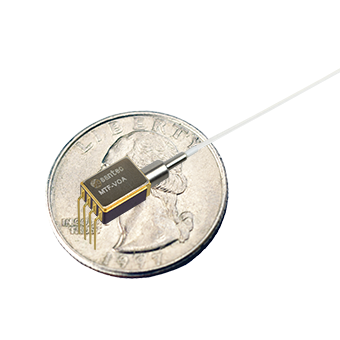
MTF-VOA is a variable optical attenuator and tunable optical filter integrated component based on electrostatic MEMS technology. It allows both tuning the center wavelength of the filter and attenuate the optical output power independently. MTF-VOA can adjust the wavelength in the range of approx. 40 nm and the attenuation range of 35 dB. MTF-VOA is compatible with Small Form Factor(SFF) industry standard compliant optical transceiver such as QSFP-DD and CDP2-DCO. The ultra compact size (7.5 x 5.5 x 3.5 mm) and low-voltage drive enable to meet the demand for optical transceiver, which are constantly being reduced in size and power consumption.
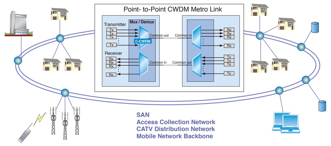
Especially designed for CWDM networks, CWDM-15 unit is optimized for wide-pass band and low loss to reduce costs and extend reach in Metro and Access equipment.
We can see that in general the light emerges in a different state of elliptic polarization. In fact, for the example illustrated above, the particular choice of L for a given difference between nx and ny causes the linearly polarized light at the input end to be converted to circularly polarized light at the other end of the birefringent material. How did this happen? Let’s look at the math. Consider the phases accumulated by the two component waves as they travel through the birefringent material. The waves can be described by
Polarization is a critical property of light for many optical systems and applications. This brief tutorial summarizes some of the most basic aspects of polarization, including how it is described, the impact of polarizing and birefringent elements on light, and how optical interfaces and filters can change the polarization of light.
Opticalfilters PDF
Most polarizing beamsplitters are very efficient polarizers for the transmitted light (i.e., the ratio of desired to undesired polarization is very high); however, the reflected light generally contains some of both polarization components.How does a polarizer work? There are different ways of making a polarizer, and they are not described in detail here (see [1] for more examples). However, as an example consider one of the most popular absorbing polarizers: the well-known Polaroid “H-Sheet.” This polarizer, invented by E. H. Land in 1938, is a plastic, Poly-Vinyl Alcohol (PVA) sheet that has been heated and then stretched in one direction, forming long, nearly parallel hydrocarbon molecule chains. After dipping the sheet into an iodine-rich ink, long iodine chains form along the hydrocarbon molecules. Electrons freely move along the iodine chains, but do not easily move perpendicular to the chains. This ability for electrons to move freely in one direction but not the perpendicular direction is the key principle upon which most absorbing polarizers are based.
Because of this relationship, a material with birefringence Dn of the appropriate thickness L to convert linear polarization to circular polarization is called a quarter-wave plate.What causes materials to be birefringent? Some materials, especially crystals, are naturally anisotropic at microscopic (sub-wavelength) size scales. For example, Calcite (CaCO3) is shown in the drawing below. The structure, and hence the response to polarized light, along the c direction is markedly different than that along the a and b directions, thus leading to a different index of refraction for light polarized along this direction.
If Ax Ay , the total wave E is linearly polarized, but it is no longer oriented at 45° with respect to the x axis. In fact we can see that it is oriented at an angle where
Optical filterdesign
C-CWDM module has been specifically designed for low cost CWDM systems where both package size and insertion loss are critical.
Optical Filterprice
Suppose the two components have equal amplitudes again, but now consider the case where these two components are not in phase, such that the angles of the sine functions are different. In particular, suppose there is a constant phase difference of p/2 between them, which corresponds to a distance of l/4 in the “fixed time” picture. The x component is
Bandpassoptical filter
The amplitude E, or the potential for a charged particle to feel a force, is vibrating along both the x and y directions. An actual charged particle would feel both of these fields simultaneously, or it would feel
where A is called the “amplitude factor,” the variable l (“lambda”) is the “wavelength” (units of nm), and the variable v (“nu”) is the “frequency” (units of Hz, or sec–1). If a snapshot of the wave could be taken at a fixed time, l would be the distance from one wave peak to the next. If one sits at a fixed point in space and counts the wave peaks as they pass by, v gives the frequency of these counts, or 1/v gives the time between peaks. The sign between the position and time terms determines the direction the wave travels: when the two terms have the opposite sign (i.e., the “–” sign is chosen), the wave travels in the positive z direction. For convenience we often use two new variables called the “wavenumber” k = 2p/l and the “angular frequency” 2pv (“omega”), which absorb the factor of 2p, so that the wave amplitude can now be written more compactly as
MDM-15 is a multi-channel WDM Multiplexer or Demultiplexer based on dielectric thin-film filter technology. The module is designed to add or drop 4/8 channels with ITU grid spacing of 100, 200 GHz.
OFM-15 is a compact and reliable bandpass filter module. It uses our proven interference filter technology and quality manufacturing techniques.
In other words, if we look down the propagation axis in the positive x direction, the vector E at various locations (and at t = 0) now looks like:
Types ofopticalfilters
WDM-15 is a compact and reliable bandpass filter module. It uses our proven interference filter technology and quality manufacturing techniques.
All of the states of polarization described above are actually special cases of the most general state of polarization, called elliptical polarization, in which the tip of the electric field vector E traces out an ellipse in the x-y plane. The two components might have unequal amplitudes Ax Ay , and also might contain a different relative phase, often denoted That is, we may write generally
The variable bandwidth – optical tunable filter is a compact MEMS-based optical component that removes noise after optical amplification in optical transceivers. While previous 1st and 2nd generation optical tunable filters could only adjust the transmitted wavelength of optical signals, our newly developed wavelength and bandwidth optical tunable filter (MTF-VB), based on santec's proprietary patented technology, can adjust not only the transmitted wavelength in the range of approximately 40 nm but also the transmitted bandwidth from 200GHz to 700GHz (3dB bandwidth). This is santec’s first compact component product supporting flexible transmission rate ,which enables ASE noise rejection with an optimal filter bandwidth for different optical signal bands from 400Gb/s to 1.2Tb/s (QPSK, 16QAM, 64QAM, etc). This product is compatible with SFF (Small Form Factor) industry standard-compliant optical transceivers such as QSFP-DD and CFP2-DCO.The ultra-compact size (9 x 5.5 x 3.5 mm) has been achieved to meet the demand for optical transceivers, which are constantly being miniaturized.
If the difference between the two phase values is p/2, then the wave emerging from the material (say into air) will be circularly polarized. This occurs when
It is also possible to take advantage of an appreciable difference in reflected or transmitted phase for p- and s-polarized light over a region of the spectrum where the reflected and transmitted intensities are essentially equal, thus forming a waveplate.
We can see that the tip of E traces out a circle as we follow the wave along the z axis at a fixed time. Similarly, if we sit at a fixed position, the tip of E appears to trace out a circle as time evolves. Hence this type of polarization is called circular polarization.
Opticalfilters HS Code
A polarizer transmits only a single orientation of linear polarization, and blocks the rest of the light. For example, a polarizer oriented along x passes x and blocks Ey.
Optical filterthorlabs
Some materials have a different index of refraction for light polarized along different directions. This phenomenon is called birefringence. For example, suppose light polarized along the x direction sees an index of nx, while light polarized along the y direction sees an index ny. Now suppose linearly polarized light passes through a piece of such a material of length L, where the linear polarization axis is oriented at 45° with respect to the x and y axes. The fixed time picture thus looks like:
When light is incident on an interface between two different media with different indexes of refraction, some of the light is reflected and some is transmitted. When the angle of incidence is not normal, different polarizations are reflected (and transmitted) by different amounts. This dependence was first properly described by Fresnel, and hence it is often called “Fresnel Reflection.” It is simplest to describe the polarization of the incident, reflected, and transmitted (refracted) light in terms of a vector component perpendicular to the plane of incidence, called the “s” component, and a component parallel to the plane of incidence, called the “p” component. The “plane of incidence” is the plane which contains the incident ray and the transmitted and reflected rays (i.e., all of these rays lie on one plane). In the example in the diagram below, the plane of incidence is the plane containing the x and z axes. That is, Es || y, while Ep lies in the x-z plane.

Unpolarized light can be polarized using a “polarizer” or “polarizing beamsplitter,” and the state of already polarized light can be altered using a polarizer and/or optical components that are “birefringent.” In this section we explore some examples of these types of components.
The amount of light output in each polarization state can be determined by simply breaking up the incident light into its two polarization components (s and p), and then calculating how much of each intensity is transmitted and reflected. For systems based on incoherent light, this level of detail is usually sufficient to keep track of the impacts of components like optical filters on polarization.For some optical systems – particularly those based on coherent light and that utilize or are sensitive to interference effects, for example – the complete state of polarization should be tracked at every point through the system. In that case, it is important to understand that optical filters based on multilayer thin-film coatings not only reflect and transmit different amounts of intensity for the s and p polarization states, but also impart different phases to the two different states. And both the amplitude and phase contributions can depend strongly on the wavelength of light. Thus, in general, an optical filter can act like the combination of a partial polarizer and a birefringent waveplate, for both reflected and transmitted light.To determine the effect of an optical filter on the light in such a system, the incident light should first be broken up into the two fundamental components associated with the plane of incidence of the filter (s and p components). Then, the amplitude and phase responses of the filter for the s and p components should be applied separately to each of the incident light components to determine the amplitudes and phases of the reflected and transmitted light components. Finally, the reflected s and p components can be recombined to determine the total reflected light and its state of polarization, and likewise for the transmitted light. These steps are illustrated in the diagram below.
and where, as before, E = Ex< + Ey. The three special cases described in sections a, b, and c above thus correspond to: (a) Ax = Ay and = 0 (linear polarization; equal amplitudes); (b)
When an optical filter is used at a non-normal angle of incidence, as is common with so-called “plate beamsplitters,” the filter can impact the polarization of the light. If the incident light is incoherent and unpolarized, and the optical system is “blind” to polarization, the standard intensity reflection and transmission functions R(l) and T(l) may be determined for the new angle of incidence, and they are sufficient to characterize the two emerging beams.
What if the two components Ex and Ey have unequal amplitude factors? We can see that the light wave is still linearly polarized.
Using this description of a single transverse orientation of a light wave, we can now consider multiple orientations to describe different states of polarization.


 Ms.Cici
 8618319014500