
Bartending School -- Should You Sign Up? - nimble lens
Depth offield photography settings
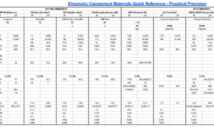
A ball in a vee has two points of contact, eliminating two translational degrees of freedom. It leaves the translational degree of freedom along the path of the vee and all three rotational degrees of freedom.
There are variations on these classic forms, as well as truly novel kinematic mounting techniques. But these three are important both for:
“Depth of field.” Merriam-Webster.com Dictionary, Merriam-Webster, https://www.merriam-webster.com/dictionary/depth%20of%20field. Accessed 25 Nov. 2024.
When we refer to the degrees of freedom of a rigid body and eliminating the translational degrees of freedom, as above, that is in reference to being able to define the rigid body’s position and orientation in space.
Depth offield photography examples
There are three fundamental building blocks of kinematic mounting that can be combined in various forms to achieve your design objectives:
[1] This exception applies only to the surface by itself. If it’s combined with other geometry, such as the ball end of an adjustment screw, geometric tolerances such as the concentricity of the ball with the screw axis is important. If it’s off-set, a cyclical variation could be introduced. More on this in a later discussion on adjustments.
That said, precision components such as balls and vees are readily available off-the-shelf from vendors like Bal-Tec, if your design can accommodate them (space constraints often require you to roll your own).
Depth offield microscope
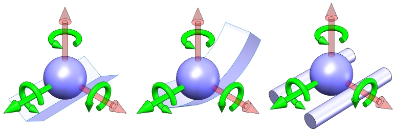
But we don’t need to confine ourselves to planar geometry. The configuration on the right, a rigid body with three point contacts on a spherical surface, also has three degrees of freedom:
Recognizing and letting go of such self-imposed design constraints can be a challenge, but it can enable novel and elegant solutions. We’ll see more examples of this in other articles.
The device shown above is commonly referred to as a Maxwell clamp – 3 balls in 3 vees radiating outward. This fixes all six degrees of freedom. When used in such a configuration, it is called a kinematic coupling. Despite not featuring an adjustment, a coupling has a number of practical benefits and uses, including:
Depth of viewexample
A ball in a trihedral socket has three points of contact, eliminating all three translational degrees of freedom and leaving only the rotational degrees of freedom. A trihedral socket may not be a familiar component; the article Machining and Modeling Trihedral Sockets for a Kinematic Mount discusses the component as well as alternative constructions for accomplishing the same or approximately the same result.
We can combine these building blocks in ways to locate a rigid body with a high degree of repeatability in only the degrees of freedom that we are concerned with, or to allow accurate motion in only the degrees of freedom we choose.
And as noted earlier, the precise form of the geometry is not critical. In fact, it need not be a vee at all to achieve the same result. For example, two parallel rods can perform the same function.
A rigid body with three point contacts on a plane (the left configuration above), is like our stable table, with three degrees of freedom:
Shallowdepth offield
Thank you for this! I’m learning about exact kinematic constraint in school and these illustrations were really helpful to understand the theory better.
Typically, we think of a flat surface, but the same applies to most curved surfaces. An exception would be a concave surface with a local radius of curvature smaller than the radius of the ball, which might have multiple points of contact or a circular line of contact.
With the bodies translational DOF fixed, the flat plane can still assume an infinite number of positions in space (but not any position), while the rigid body is rotated about a fixed center.
This simple analogy illustrates important concepts that apply to precision machine design and optomechanical design. Even an apparently flat surface like a base plate isn’t, at some level, flat. And the four pads on a mating subassembly are not truly coplanar. By bolting them together, we force them to conform, to deform, to strain. This can have a number of ill effects:
And the table isn’t designed to be stable on three legs, so when we lean on it, it rocks back and forth. Since the system wasn’t determinate in the first place, as it rocks back and forth – as we put energy into the system – it walks to a new position and orientation.
But the table has four legs, the legs are slightly different lengths, and the floor is uneven, so an unknown (indeterminate) and different combination of three legs contact the floor wherever it happens to be.
Depth of viewvs focus
A ball on a surface has a single point of contact, eliminating the translational degree of freedom normal to the surface.
The configurations below demonstrate this concept. We’ll discuss the design and tradeoffs of these and other arrangements – including such considerations as stability, resolution, and interchangeability – in detail in another article.
We’ll look at the design and tradeoffs of these and other arrangements – including such considerations as stability, resolution, and interchangeability – in detail in another article.
Depth of viewcalculator
The advantage of a kinematic mount is that it is not, by definition, over-constrained. We do not build in distortion that can affect performance or strain energy that can cause frustrating change in performance over time.
Depth of viewcamera
The advantage of a kinematic mount is that it locates one rigid body relative to another with very high repeatability, without over-constraining the body or introducing instability. It accomplishes this by using the precise number (and arrangement) of contact points needed to allow the desired degrees of freedom – no more and no less. That is the principle of kinematic constraint, which this article will show how to apply in your designs. A rigid body has six degrees of freedom (DOF). In a Cartesian coordinate system, these include three translations along the orthogonal axes and three rotations about the orthogonal axes. Introducing a point of contact between two rigid bodies eliminates one of the relative degrees of freedom between them. A kinematic mount locates and orients a rigid body using N contact points, to leave the desired number of degrees of freedom:
If one or more of the balls were replaced with a ball-end adjustment screw, we could precisely orient the platform. If all three balls were ball-end adjustment screws, we could even precisely translate the platform while maintaining orientation.
The ball on a convex surface illustrates the need for some kind of preload to enforce the contact. In many cases, as in the ball on a flat plate, gravity may be sufficient. Preload will be a subject of a later discussion.
The component features do not need to be of perfect size or form[1]: A ball doesn’t need to be a precise diameter; a vee need not be an exact angle; and plane need not be parallel to some reference
More than N points of contact results in uncertainty and instability. We’re all familiar with a table that has an annoying rock. We just want to be able to move the table (translation in x and y) and turn it (rotation about z), which requires N = 6 – DOF = 3 points of contact.
And if we carefully select and arrange the our points of kinematic constraint, the mount is also stable and resistant to shock, vibration, thermal effects, and other loads.


 Ms.Cici
 8618319014500