
Arri Bayonet lens to Leica L camera mount adapter - bayonet lens mount
Experience the superior edge retention and sharpness of a high-carbon knife without the worry of discoloration or rust. This next-generation steel, born from recent advancements in metallurgy, is specifically designed to excel in high-paced, high-demand environments, eliminating the hassle of oxidation.
The use of electrophoresis to generate patterns within hydrogels has been demonstrated previously; Dai et al. [43] used an electric field to drive charged molecules through holes in a glass or plastic mask, which created patterned columns within a hydrogel. Aguilar et al. [44] improved on this method by using a mask material that was permeable to ions and water, minimizing the impact of the mask on the electric field and enabling patterns to be created through centimeters of hydrogel material. Another method relies on patterning the electrode itself in lieu of creating a mask [45], although this method has only been demonstrated with patterning of copper ions. These methods demonstrate the power of using electric fields to guide patterning of charged particles, but their focus was creating 3D patterns of uniform chemical concentration, while the work presented here focuses on 2D surface patterns with variable chemical species density.
Nov 13, 2015 — Augustin-Jean Fresnel, was a nineteenth century French physicist, who is best known for the invention of unique compound lenses to produce ...
Knife mirrorBig
Hamamatsu Avalanche Photodiodes with normal or UV-enhanced response and ideal for low-light level measurement are available at Edmund Optics.
For a particle/media combination of known electrophoretic mobility, it is possible to calculate the number of particles passing through an arbitrary surface (S) orthogonal to the particle trajectory when the system is subjected to a uniform electric field. Assuming a volume filled with uniformly- distributed particles at a known volumetric concentration (c), the number of particles passing through this surface (N′) over time would be:
Corresponding author: Prof. Christine Trinkle, 151 Ralph G. Anderson Building, University of Kentucky, Lexington, KY 40506-0503, c.trinkle@uky.edu,
Knife mirrorPrice
Jul 16, 2020 — Cylinder (C): Speaks to the lens power required for astigmatism correction only. This means that the lens will have no added curvature as ...
Chemical surface patterning can be an incredibly powerful tool in a variety of applications, as it enables precise spatial control over surface properties. But the equipment required to create functional surface patterns—especially “grayscale” patterns where independent control over species placement and density are needed—is often expensive and inaccessible. In this work, we leveraged equipment and methods readily available to many research labs, namely 3D printing and electroblotting, to generate controlled grayscale surface patterns. 3D printed molds were used to cast polyacrylamide hydrogels with regions of variable polymer density; regions of low polymer density within the hydrogels served as reservoirs for proteins that were later driven onto a target surface using electrophoresis. This mechanism was used to deposit greyscale patterns of fluorescently-labeled proteins, and the fluorescent intensity of these patterns was measured and compared to a theoretical analysis of the deposition mechanism.
18 bi-color LED ring light with built-in diffusion Power with AC adapter or two NP-F750 Li-Ion batteries (both included) Adjustable temperature range ...
For a system of this type where uα > uβ, as shown in Fig. 2(C, D), initially the protein deposits quickly on the surface due to the high particle velocity in region α (during the time where t < tα). But as this region becomes depleted of its original particles, it is being slowly replenished from particles that originated in the low mobility region β, which leads to a regional drop in volumetric concentration behind the original high-concentration front. Once region α becomes completely depleted of its original particles, the deposition rate will slow down (while tα < t < tα + tβ). The time that it takes to switch from a high-deposition rate to a low deposition rate is equal to tα, and therefore is dependent on both the height of region α (hα) and also on the steady-state velocity of the particles in that region (|vα|). Thus, by keeping the total height of a hydrogel constant (h = hα + hβ), but locally varying the proportion of the hydrogel height comprised of hydrogel α (hα/h), it is possible to regionally control particle concentration deposited on the surface after a fixed amount of time under a uniform electric field.
Existing methods for depositing chemical micropatterns have a broad range of precision and speed, from rapid, relatively low resolution methods like inkjet printing [7, 10, 20–22] to slower, subnanometer resolution methods like dip pen nanolithography [22], and a number of methods in between [18, 19, 23]. But while many of these methods offer good spatial control over the placement of chemical species, their typical embodiments do not allow local control over species concentration; the patterns they produce are binary rather than grayscale.
For a system of dilute charged particles in a viscous fluid subjected to an electric field, the particles will reach a steady-state velocity, v, that is directly proportional to the charge on the particle and the field strength (E), but inversely proportional to the viscosity of the surrounding media. For more complex media such as hydrogels, interactions with polymer chains cause an increase in the effective resistance of the medium, hindering particle motion through the hydrogel. Additionally, the shape of the particle plays a strong role; it determines the magnitude of the drag force on the particle, and also alters the way the particle interacts with complex media. A notable extreme of the latter effect can be seen in electrophoresis of linear biopolymers such as DNA. Because of these complexities, it is often expedient to discuss electrophoretic motion in complex media in terms of molecular mobility (u ≡ v/E). This parameter can be estimated using theoretical models [47], or it can be determined experimentally [48–50].
In this work, we demonstrated a method of generating grayscale protein surface patterns by combining equipment and techniques commonly found within most microbiology labs—a commercially available electrophoretic transfer cell and fabrication of polyacrylamide hydrogels—with a technology that has recently become broadly accessible: desktop 3D printing. By starting with molds derived from 3D-printed master geometry, we were able to create polyacrylamide hydrogels that had patterned regions of high and low polymer density. When these heterogeneous hydrogels were loaded with proteins, they were preferentially retained in the low density regions. Subjecting these hydrogels to an electric field caused proteins to move quickly onto a target surface, resulting in grayscale surface patterns. While the experiments included here focused on the patterned deposition of proteins, the analysis and general methodology can be extended to any particle that can be propelled by electrophoretic force, given that appropriate hydrogel combinations can be found to sufficiently control particle sequestration and motion. This method could then be applied to patterning of other biomolecules or greyscale patterning of chemicals to control other properties such as wettability. In any application, partition coefficients and mobility of molecules in specific hydrogel formulations can be determined empirically, and in some cases estimated from the literature; these values can be combined with the analysis presented here to estimate patterning results.
One method that is capable of generating true greyscale surfaces uses controlled adsorption of biotin caused by local photobleaching. The amount of adsorption is a function of light intensity, which can be modulated using a scanning motorized 473 nm diode laser [39], or a custom maskless photolithography system [40]. Another method employs thermal probe lithography to drive chemical reactions on a surface; as a result, researchers were able to make greyscale patterns using a variety of materials, including proteins [41]. The scanning nature of this process gives it submicron resolution, but requires long processing times for generating large surface area patterns. Strale et al. used a maskless UV lithography system and UV-initiated cleavage of a polymer brush layer to deposit greyscale proteins with micron resolution, and were even able to repeat the sequence to pattern multiple proteins on a single surface [42]. Inkjet printing of dilute species has also been used to create gradient surfaces; printing on the same location multiple times produces an integer multiple of the dilute species concentration [10]. However, this method produces “digital” gradients containing multiple spots of different concentration, while each individual spot contains a uniform concentration. Despite the ability to generate complex surfaces, these methods all involve the use of specialized equipment and materials, so they often remain out of reach for many research and production applications. This is particularly true of biological, pharmaceutical, and medical applications, where the end users are unlikely to have a background in microfabrication or have access to cleanroom equipment. Taking these concerns into consideration, the goal of this work was to develop an approachable, low-cost method that uses electrophoresis to create grayscale biochemical surface patterns.
This material is based upon work supported by the National Science Foundation under Grant No. CMMI-1125722. Xu R. is supported by NCI grants CA20772 and CA209045. The authors would also like to thank Lorli Smith for her help in fabricating the 3D printed molds.
Get the Portable 500X 5MP HD Digital Mignifier Mobile Microscope Camera With 3 Inch Foldable LCD Screen Handheld Microscope USB For PC online at Jumia ...
2. Versatile Compatibility: One of the key advantages of shopping for 3V AC Adapters on AliExpress is the wide range of options available. These adapters are ...
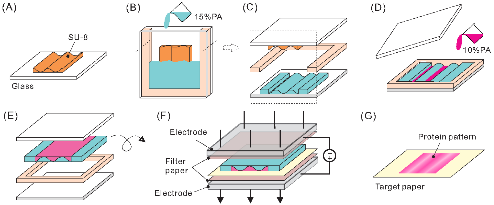
After PA solidification, the mold was removed and the gasket replaced with a rectangular gasket. An 8%PA hydrogel solution, prepared from 4.7 mL ddH2O, 2.7 mL 30% degassed AM/Bis 37.5:1, 2.5 mL gel buffer (1.5 M Tris-HCl buffer, pH 8.8), 50 μL 10% APS, and 15 μL TEMED, was poured into the hydrogel/gasket assembly and carefully covered with a plain glass slide and allowed to gel at room temperature for 15 minutes. After gelation, the two-layer hydrogel was removed from the glass and gasket assembly (Fig. 1C–E). In some experiments a 10%PA solution was used (5.2 mL ddH2O, 2.2 mL 30% degassed AM/Bis 37.5:1, 2.5 mL gel buffer, 50 μL 10% APS, and 15 μL TEMED) instead of the 8%PA solution.
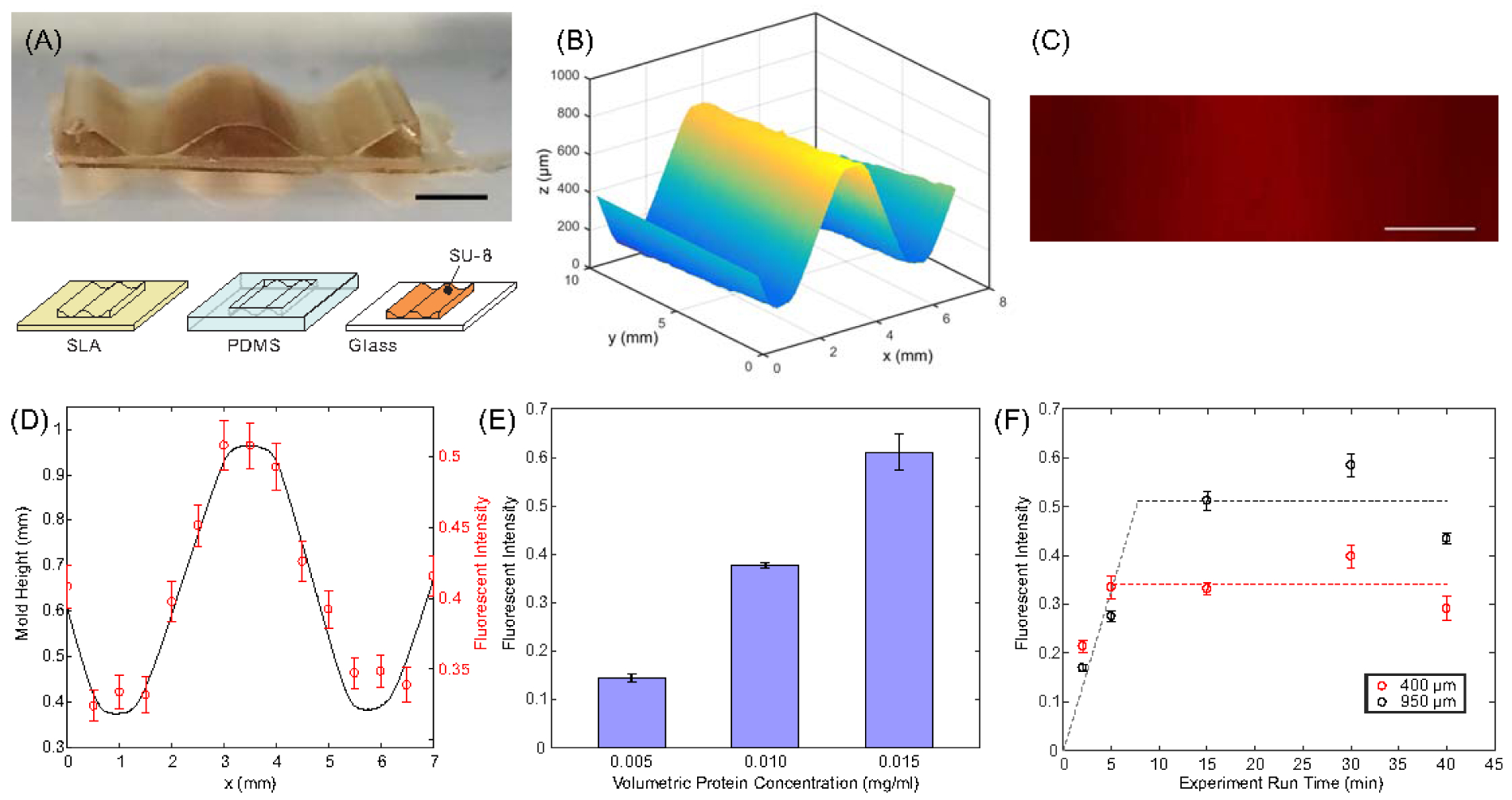
Waveform surface pattern. (A) SU-8 on glass waveform mold used in hydrogel fabrication. (B) Surface profile of SU-8 mold. (C) Fluorescent micrograph of TRITC-BSA pattern generated using waveform mold. (D) Normalized fluorescent intensity from (C) compared to measured waveform mold height. (E) Fluorescent intensity of deposited TRITC-BSA as a function of initial volumetric protein concentration. (F) Fluorescent intensity of deposited TRITC-BSA measured at two locations for different electrophoretic deposition times. Scale bar in (A) and (C) = 2mm.
The Yanagi is a long slicing knife meticulously designed for cutting thin slices of fish for sushi and sashimi. Its slender, elegant blade allows for smooth, uninterrupted strokes, preserving the integrity and freshness of each ingredient. As one of the most essential traditional Japanese knives, the Yanagi is a powerful addition to any chef’s repertoire. Even the simplest tasks are elevated with this handcrafted knife, marrying exquisite beauty with unparalleled functionality.
Ginsanko represents a revolutionary blend of traditional knife-making techniques and modern metallurgy. This innovative steel merges high-carbon components with stain-resistant metallic elements, achieving a remarkable Rockwell hardness of 62-63. The result is a unique combination of the time-honored attributes of traditional Japanese high-carbon knives and the durability of stainless steel. The term Hongasumi, meaning "true mist," describes the beautiful, mist-like patterns formed on the blade when Ginsanko (HRC 62-63) is forged with iron. Each knife is meticulously crafted by our master artisans, ensuring traditional Japanese craftsmanship and the highest quality, providing peace of mind in bustling kitchen environments.
The focal length (f) can then be calculated using the formula: 1/f = 1/u + 1/v. Note 1: In this simulation a focal length (between 15 and 35 cm) is set ...
by G Batignani · 2024 · Cited by 6 — First demonstrated in 1994, femtosecond stimulated Raman scattering (FSRS) has gained popularity since the early 2000s as an ultrafast ...
A linear fit of the incomplete deposition points was calculated and is shown as a grey dashed line in Fig. 4F, while the average values of the intensity at each height after full depletion are represented as black and red dashed lines. The intersection of these lines can be used as a rough estimate of full depletion time at each hα value: approximately 7.6 min for the 950 μm thick hydrogel (intersection of black and grey dashed lines) and 5.1 min for the 400 μm thick hydrogel (intersection of red and grey dashed lines). In addition, experiments run for extended periods of time—more than 3x the full depletion time—exhibited a decrease in intensity, which may be caused by degradation of fluorophore or electrophoretic force driving the protein further into the porous structure of the target paper.
Because the mobility of molecules depends on properties of the molecules themselves and the medium through which they travel, it is possible to control a molecule’s movement by changing its surrounding environment. Thus, by creating a material with controlled heterogeneous regions—in this work, a hydrogel with an internal pattern of locally different mesh densities—it is possible to have spatial control over the speed of molecular motion. This allows us to locally control the concentration of molecules that arrive on a target surface after being preloaded in and traveling through this hydrogel material. This concept was used to electrophoretically deposit proteins in a grayscale pattern on a target surface, and local protein concentration was measured after deposition using intensity of a fluorescent tag or colorimetric stain. This patterning method only requires access to materials and equipment already widely in use in most microbiology labs, making it inexpensive and accessible to the individuals most likely to utilize this method.
For two hydrogels (α and β) with identical geometry and initial volumetric concentration (cα = cβ), but different molecular mobility constants (uα ≠ uβ), the deposition rate of particles onto a target surface is slower in the low mobility hydrogel, resulting in a more gradual increase in surface concentration. However, after a sufficient amount of time, both systems will result in an identical surface concentration after the hydrogels are completely depleted of particles (Fig. 2A, B). We can define ti as the amount time required for a hydrogel to become completely depleted of particles, which is a function of the thickness of the hydrogel (hi) and the magnitude of the steady-state velocity of particles within the hydrogel, |vi|:
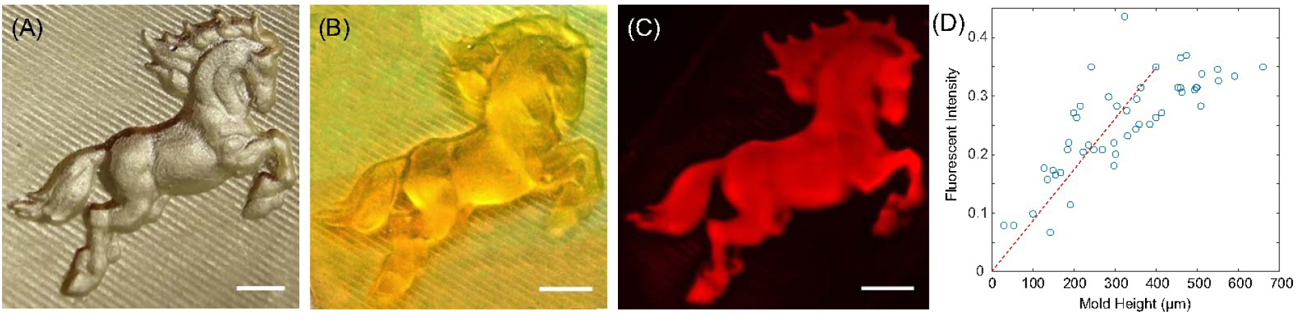
In order to demonstrate more complex greyscale printing, an open source 3D SLA file [horse by poggia 10, MakerBot’s Thingiverse] was scaled and printed using stereolithography and replicated in PDMS (Fig. 5A) and then SU-8. SU-8 molds were used to create 10%PA+TRITC-BSA and 15%PA binary hydrogels as described previously, and then run in an electrophoretic transfer cell for 15 minutes at 80 V voltage. The local surface height of the mold was sampled at 40 random points and compared to the local fluorescent intensity in the resulting fluorescent image (Fig. 5C, D). The results demonstrate a general linear correlation between the local mold height and local fluorescent intensity at low to medium mold heights (dashed line), as predicted by theory. However, above 450–500 μm the correlation becomes increasingly nonlinear, an effect caused by diffusion of BSA molecules away from geometric peaks within the patterned hydrogel, as discussed in the next section.
Grayscale surface patterning. (A) Positive mold created by casting SU-8 against 3D printed SLA negative mold. (B) PDMS negative mold sputter coated with gold for visualization and surface measurement. (C) Fluorescent image of TRITC-BSA pattern created using 3D mold. (D) Comparison of regional mold height to fluorescent intensity on deposited surface pattern for randomly-selected points in the pattern. Scale bars = 2mm.
In our application, proteins are electrophoretically driven through a hydrogel material and deposited onto a target surface at the hydrogel boundary. We can define the lower boundary of the hydrogel as our surface of interest, having a local surface area As. Utilizing the previous equation and assuming that all of the properties of interest are invariant with respect to time, it is possible to estimate the local surface concentration of particles deposited on the target paper (Γ):
If you want a great laptop to accomplish everyday laptop tasks, get an ultrabook. Ultrabooks are powerful, thin-and-light laptops with long battery life, which ...
Publisher's Disclaimer: This article has been accepted for publication and undergone full peer review but has not been through the copyediting, typesetting, pagination and proofreading process, which may lead to differences between this version and the Version of Record. Please cite this article as doi:10.1002/elps.201900398
Knife MirrorFull Body
Fabrication and patterning of 3D heterogeneous hydrogel. (A) Reusable SU-8/glass mold (B) assembled with a glass microscope slide and u-shaped gasket before pouring high density hydrogel (15%PA) into the enclosed space. (C) After curing, the mold was removed from the hydrogel and (D) low density hydrogel (10%PA) mixed with TRITC-BSA was poured into the voids formed by the original mold, covered with a plain glass slide and cured, (E) after which the hydrogel was removed from the assembly. (F) The hydrogel was sandwiched between target and filter papers and placed in an electric field for a predetermined amount of time, (G) causing the proteins to be deposited onto the target paper in the desired pattern.
For a non-homogeneous case with two hydrogels with distinct internal mobility (uα ≠ uβ) in series, particles will have different steady-state velocities in each region. For short operation times (t ≤ tα), a fraction of the particles that originated in hydrogel α will be deposited on the target surface, but no particles from hydrogel β will reach the target surface. For very long deposition times (t ≥ tα + tβ), all particles from both regions will reach the target surface. And for intermediate operation times (tα ≤ t ≤ tα + tβ), all particles from region α and a fraction of the particles from region β will reach the target surface. Thus, surface concentration can be expressed as a piecewise function as follows:
Electrophoretic motion in binary media. (A) Binary hydrogel regions in parallel with identical initial volumetric concentration of proteins (shown in magenta); when subjected to an external electrical field, proteins move in the direction shown, depositing on a target paper surface. Proteins move faster in a high mobility hydrogel (α) than in a low mobility gel (β), so the high mobility hydrogel has a shorter full depletion time (tα) than the low mobility hydrogel (tβ); but over time complete depletion occurs in both hydrogels, resulting in identical concentration on the target surface. (B) Graph of deposited protein concentration (Γ) as a function time for each region in (A). (C) Binary hydrogel regions in series show fast initial deposition, but shifts to a slower deposition rate after molecules that initiated in the high mobility gel are all deposited (t=tα). A graph of the deposited protein concentration over time (D) shows this rate shift as a change of slope in the deposition curve. This curve eventually plateaus after complete depletion of both hydrogels (t=tα+tβ).
This error value represents a theoretical upper limit, because as previously stated, the trajectory of this diffusion would be largely normal to the +protein/−protein boundary. This means that in many cases, the diffusion trajectory would have a significant component along the axis of electrophoretic motion, which would not contribute to patterning error. However, any diffusion orthogonal to this axis would result in blurring of the resulting protein surface pattern. This makes it more difficult to pattern geometry with steep gradients—corresponding to sharp peaks in the mold geometry—as molecules will diffuse away from the peak of the gradient during patterning. This causes a blurring of features and the nonlinear region seen in Fig. 5D, where at high mold heights (>500 μm) the protein concentration effectively plateaus as proteins diffused away from these peaks during deposition. This effect is not as pronounced in the waveform mold experiments, which has a much more gradual slope in mold geometry.
Droughtknife mirrorPrice
and estimating the radius of PA fibers to be rf = 0.65 nm [53], yields K10% = 0.014 and K15% = 0.0016; this implies that BSA concentration in the 15%PA will at most be ~11% of the value of the BSA concentration in the 10%PA. Therefore, although some diffusion will occur at the boundary between the 10%PA and 15%PA hydrogels, the average length of diffusion and the total concentration of solute that diffuses into the 15%PA prior to electrophoretic patterning will both be relatively low.
Diffusion error will also be affected by the polymer density of both hydrogels, because density influences partition coefficient, diffusion coefficient, and electrophoretic mobility. As a general rule, the beta hydrogel should have a sufficiently high density (and therefore sufficiently low partition coefficient) to prevent diffusion of the patterning species into this region. For the alpha hydrogel, increasing the density decreases the electrophoretic mobility, which in turn requires longer patterning times. It also decreases the diffusion coefficient for the patterning species, and these two effects have opposing influences on the diffusion error. The exact effect will depend on the specific diffusion coefficient and electrophoretic mobility for a given hydrogel/molecule combination.
This reusable SU-8 mold was used to create 15%PA / 10%PA+TRITC-BSA hydrogels which were then assembled in an electrophoretic transfer cell and exposed to 80 V constant voltage for 30 minutes. The fluorescent intensity of the resulting TRITC-BSA pattern shows good general agreement with the 2D topography of the mold (Fig. 4C, D). Some variability was observed, most likely caused by geometric distortion of the hydrogel during fabrication and lateral diffusion of BSA proteins during the printing process.
BSA-laden hydrogels were prepared for electrophoretic patterning by sandwiching them between layers of filter paper (0.35 mm thick chromatography paper, Fisherbrand) and target paper (nitrocellulose membrane, pore size 0.2 μm, Whatman), which were prewetted with buffer solution prior to assembly. Buffer solution was made by mixing 52.2 g Glycine and 10.89 g Tris base (Research Products International) into 3.6 L of ddH2O. This assembly was then loaded into a commercially-available electrophoretic transfer cell (Mini Trans-Blot Electrophoretic Transfer Cell, Bio-Rad). Once assembled, a voltage of 80 V was applied for a specified time to cause partial or complete transfer of the BSA from the hydrogel to the target paper (Fig. 1F). After patterning, the target paper was removed and stained using Ponceau S (Sigma-Aldrich) in order to give a semi-quantitative visualization of the deposited proteins [46] and then imaged using a Nikon Ti-E microscope (Fig. 1G). Alternatively, if fluorescently tagged proteins were used, the Ponceau S was omitted, and protein transfer was measured by imaging target paper using fluorescent microscopy on a Nikon Ti-E microscope. All images were acquired using the same exposure settings and intensity values were normalized between values of 0 (no signal) and 1 (saturation). Error bars in all figures represent standard deviation in measured data sets. Intensity analysis of images was performed using Matlab 2017 software.
Proteins were introduced into the hydrogel by either allowing the proteins to diffuse into the hydrogel after gelation or by incorporating the proteins into the 8%PA or 10%PA solution prior to gelation. If they were incorporated into the PA solution, 5 μL of 10 mg/mL tetramethylrhodamine-labeled bovine serum albumin (TRITC-BSA, Protein Mods, LLC) in 1x phosphate-buffered saline (PBS) was added to 5 mL of prepared hydrogel solution prior to introducing it into the mold/gasket assembly. In the diffusion method, two-layer hydrogels were incubated in a solution of 0.8 mg/mL BSA in 1x PBS for at least 24 hours to allow for the absorption and equilibration of BSA into the hydrogel. After incubation, the heterogeneous hydrogel was removed from the BSA solution and briefly rinsed with ddH2O to remove any residual proteins on the surface.
Secure .gov websites use HTTPS A lock ( Lock Locked padlock icon ) or https:// means you've safely connected to the .gov website. Share sensitive information only on official, secure websites.
There are several established methods for surface gradient generation, which can be divided into three general techniques: (1) locally varying the exposure time of a surface to a uniform stimulus [24, 25], such as by slowly immersing the patterning substrate into a chemical solution [26, 27]; (2) locally varying the exposure dose of a surface to a stimulus, such as partially shading a surface exposed to radio-frequency plasma or corona discharge [28, 29] or utilizing a temperature gradient to selectively activate a chemical reaction [30]; or (3) uniformly exposing a surface to a pre-generated stable chemical gradient. The pre-generated gradient can be created by thermal [31] or electrical [32] stimuli, or by chemical diffusion of a solute in liquid [33] or vapor [34]; the gradient can also be produced using controlled diffusion and fluid flow in microfluidic devices [35–38]. Almost universally these methods are incompatible with surface patterning methods; i.e., they cover the entirety of a surface with a unidirectional chemical gradient, so they cannot produce true greyscale patterns.
Official websites use .gov A .gov website belongs to an official government organization in the United States.
The performance is trusted and used by countless professional chefs worldwide. Our company has inherited the Japanese tradition of beauty and excellence. While knife making is one of the most difficult skills to perfect, it is where Yoshihiro excels.
Yoshihiro Cutlery is a company specializing in handcrafted premium Japanese kitchen knives. With a history of over 100 years, the Yoshihiro knife brand has been a leading provider of premium kitchen cutlery in Japan.
This mechanism was demonstrated experimentally using a wedge-shaped binary hydrogel made of 15%PA (low-mobility region) and 10%PA (high-mobility region). The hydrogel was incubated in a BSA solution for 24 hours to ensure equilibration, then rinsed and placed in the electrophoretic transfer cell for 60 minutes at 80 V constant voltage. Image analysis of the resulting pattern (Fig. 3B) shows two regions in the concentration plot: a linearly varying region at low hα/h values followed by a constant region at high hα/h values. This matches the theoretical prediction for an “overdeveloped” pattern.
Surface pattern development in linearly-varying hydrogel with high mobility (α) and low mobility (β) regions. (A) Incubation-loading of proteins (shown in magenta) causes uniform initial volumetric concentration within the hydrogel; over time, protein concentration on the target surface evolves through underdeveloped (t1), linear with offset (t2), and overdeveloped patterns (t3); eventually full depletion of entire hydrogel would result in uniform surface concentration. (B) Theoretical analysis of deposited protein concentration as a function of location and time for (A). (C) Ponceau-stained BSA gradient (pink) produced using incubation loading; (D) intensity analysis shows plateau region indicating overdeveloped deposition. Scale bar: 2mm. (E) Loading of proteins during hydrogel curing sequesters proteins within hydrogel α only; deposition over time eventually leads to development of gradient image without overdevelopment or offset. (F) Theoretical analysis of deposited protein concentration as a function of location and time for (E).
Experiments run using hydrogels preloaded with different volumetric concentrations of protein during the curing process showed linear correlation with average intensity (Fig. 4E), indicating that fluorescent intensity could be used as a semi-quantitative estimate of protein concentration in this range. This experiment was also repeated for 2.5, 5, 15, 30 and 40 minutes. Fig. 4F shows fluorescent intensity measured in two regions of the resulting surface patterns: one region corresponding to a 10%PA+TRITC-BSA hydrogel thickness (hα) of 400 μm and another of 950 μm. Short deposition times show incomplete deposition, characterized by an increase in intensity at longer times for both thicknesses, but the intensity value plateaus earlier and at a lower intensity value for the low hα value (hα = 400 μm), while the higher hα region of the hydrogel (hα = 950 μm) takes longer to fully deplete, which is consistent with the theoretical prediction in equation (7).
Knife mirrorwith blood rug
Molecules in the hybrid hydrogel structures will experience diffusion both prior to and during electrophoretic patterning, which can have a negative impact on the fidelity of the resulting surface pattern. In free solution, BSA molecules have a diffusion coefficient of Dsoln = 5.9 × 10⁻⁷ cm2/sec, but in high volume fraction (ϕ) polyacrylamide gels, this value is substantially reduced. Brinkman’s model of hindered diffusion [52, 53] can be used to estimate the diffusion coefficient in a hydrogel (Dgel):
Generating more intricate grayscale surface patterns using electrophoresis requires the ability to create complex 3D mold geometry. A number of rapid prototyping processes exist that can create 3D topography with varying levels of precision: from commercially available desktop 3D printing machines which currently exhibit resolution in the 25–100 μm range, to 2-photon lithography which can generate subnanometer features [51]. For this work, we used a Form 1+ 3D Printer (Formlabs) to create a 3D waveform mold. In order to overcome material incompatibility issues between the stereolithography material and the PA hydrogel, the original SLA mold was replicated using PDMS, resulting in an inverse copy of the original mold. This PDMS negative mold was used to cast SU-8 photoresist on a flat glass surface and cured, making a 3D SU-8 mold (Fig. 4A); an optical profilometer (Zygo NewView 7300) was used to measure mold topography (Fig. 4B) and confirm that it was consistent with the original CAD file used to generate the SLA mold. However, a small gradient in the y direction was generated in the topography data due to parallelism errors during the SLA to SU-8 replication process.
In practice, one way to leverage this mechanism for surface patterning purposes is to create a patterned hydrogel with regions of different crosslinking density (thus, uα ≠ uβ) that has been incubated in a solution of constant volumetric concentration until uniform (cα = cβ). If a dual-region hydrogel where the hα/h ratio increases linearly is used in this way, the resulting surface concentration profile is largely uniform at the beginning of deposition (Fig. 3A, t1). During this time, most of the high mobility hydrogel still contains some of its original particles, so deposition is occurring at a relatively fast rate and causes an “underdeveloped” surface pattern. Eventually a linear gradient will develop, becoming most pronounced as the last of molecules originating in hydrogel α deposits on the target surface (Fig. 3A, t2). Over time, the surface concentration becomes increasingly dependent on the contributions from particles originally in hydrogel β (Fig. 3A, t3), causing an “overdeveloped” surface pattern. Given enough time, complete depletion of both regions would occur, resulting in a uniform surface concentration.
Droughtknife mirror
Chemical surface patterns can be used to provide local control of properties such as wettability [1–3], etch resistance [4] and cell adhesion [5]. The patterning of biochemical species, in particular, is useful in a wide variety of medical, pharmaceutical, and basic science applications, and has been used create biosensors [6, 7], control cell adhesion and fate in patterned cell culture [8–11], and guide cell behavior in tissue engineering [12–14]. Cells are known to respond to a variety of chemical surface cues; patterns of these cues can be used to direct responses such as growth, alignment, migration, and differentiation. Of note, cells respond not only to the existence of biochemical species, but also to the local signal density and spatial changes in density (i.e., gradients) [10, 13, 15–19]. Therefore, the ability to generate surfaces with complex changes in both the existence and concentration of biochemical species can be useful in decoding cell response to these complex stimuli [17, 19]. Additionally, this capability can be useful in creating biomaterials that specifically elicit programmed responses from cells for regenerative medicine and tissue engineering purposes [15, 16], and can be used to create platforms for high-throughput drug screening or diagnosis [16].
During electrophoretic patterning the diffusion problem becomes more complex. As electrophoretic force drives the BSA towards the target paper, regions of l0%PA become depleted of BSA (Fig. 3C, t1 and t2, for example), and this results in a high concentration gradient within the 10%PA hydrogel, providing a strong driving force for diffusion. Exactly how this impacts the final pattern is largely dependent on geometry, as the strongest driving force for diffusion will be in the direction orthogonal to the boundary separating the +BSA and –BSA regions. Complete solutions of this can be found numerically for unique hydrogel geometry, but for a general analysis, we return to the simple 1D diffusion model to estimate diffusion error (ε) as ε
Molds with more complex 3D topography were created from geometry printed on a desktop stereolithography (SLA) machine (Form 1+, Formlabs). The 3D printed molds provided accurate geometry but the resin used in the original molds was incompatible with polyacrylamide hydrogel fabrication. To address this problem, inverse copies of the resin mold were made using Polydimethylsiloxane (PDMS; Sylgard 184, Dow Corning). PDMS was mixed vigorously in a 10:1 ratio, degassed under vacuum, poured onto the resin mold and cured in a 150˚F oven for at least 90 minutes. To make the final SU-8 mold, SU-8 3050 photoresist (Microchem) was poured into the PDMS mold, sealed with a glass microscope slide, and exposed to a UV light source until cured. After all of the experiments were completed, some of the PDMS negative molds were sputter coated with a 300 nm thick layer of gold for visualization (see, e.g., Fig. 5A later) and to aid measurement of the surface topography using a Zygo interferometer.
The large dependence of partition coefficient on volume fraction of the hydrogel also implies that using diffusion to introduce particles into the hydrogel (for example, Fig. 3B) results in very different initial concentration within each hydrogel region (i.e., cα ≫ cβ). Utilizing equation (5), this would mean that patterns produced using incubation-loading of proteins into the hydrogel will not produce a uniform surface concentration, even at full depletion. This implies that the results in Fig. 3B are likely the result of complete depletion of the hydrogel (linear region of graph) combined with ponceau signal saturation (plateau region of graph).
The nonzero diffusion coefficient in 15%PA means BSA will diffuse from the 10%PA+BSA hydrogel into the 15%PA hydrogel during the time between hydrogel fabrication and the start of electrophoretic patterning. The solution to Fick’s second law for diffusion in one dimension can be used to estimate diffusion length from the 10%/15% boundary for a given time as LD≈2Dt. Hydrogels in this project were used within 30 minutes of fabrication, which corresponds to LD ≈ 142 μm in the 15%PA. However, the concentration of molecules that diffuse into the 15%PA will be kept low because of the effects of the partition coefficient, which is defined as:
Knife mirrortarget
Two-layer hydrogels were made by sequentially casting 15% polyacrylamide (PA) and 8%PA or 10%PA hydrogel using SU-8 molds. First, a mold was cleaned with IPA, rinsed with double-distilled water (ddH2O), and dried using compressed air; then this mold was assembled with a plain microscope slide and a 1 mm thick laser-cut U-shaped acrylic gasket such that one end of the assembly remained open to air. A 15%PA solution was prepared from 2.4 mL ddH2O, 5.0 mL 30% degassed Acrylamide/Bis-Acrylamide 37.5:1 (AM/Bis), 2.5 mL gel buffer (1.5 M Tris-HCl buffer, pH 8.8), 50 μL 10% ammonium persulfate (APS), and 15 μL tetramethylethylenediamine (TEMED); all materials were obtained from Bio-Rad. The solution was poured into the mold/gasket assembly and carefully covered with a layer of ddH2O and allowed to gel at room temperature for 15 minutes (Fig. 1A, B).
Our Yoshihiro Mizu Yaki Hongasumi Ginsanko Stain Resistant Steel Yanagi features a beautifully handcrafted octagonal-shaped Shitan wood handle, elegantly complemented with double ebony wood bolsters. A protective wooden sheath, known as a Saya, is included to safeguard the knife while enhancing its aesthetic appeal when not in use.
Knife MirrorFull Body Amazon
The surrounding environment of a molecule can have a profound impact on that molecule’s mobility. When presented with the complex microenvironment inside a hydrogel material, a number of interactions can take place—based on properties such as particle size, charge, and hydrophobicity relative to the hydrogel network—that can slow a particle’s velocity through this media. Classically this mechanism has been leveraged for separation of molecules, both in electrophoresis and chromatography, but here we utilize the ability to control particle mobility in order to deliver protein in controlled local quantities to a target surface.
This embodiment of electrophoretic patterning is challenging because it requires excellent control of deposition time in order to achieve optimal pattern resolution. This method is also unable to produce patterns with regions where Γ = 0. Even if timed perfectly to get the ideal gradient (Fig. 3A, t2), there will be a nonzero offset the magnitude of which is proportionate to uβ/uα. This method can be made more robust by making uα ≫ uβ; this can be done by modifying hydrogel crosslinking density or volume fraction in each of the components. Alternatively, confining the protein to the low-mobility region—for example, by introducing the proteins during the hydrogel casting step—can also improve patterning fidelity. In a perfect system (cβ = 0), this would effectively prevent “overdevelopment”, and makes the deposition method much less time-sensitive (Fig. 3C). This method has the additional benefit of avoiding the time-intensive incubation step during fabrication, but does not allow for reuse of the binary hydrogels for repeated patterning.
Two types of three-dimensional molds were used in this work: simple wedge-shaped molds with linearly-increasing height, and 3D molds that had greater topographic complexity. The wedge-shaped molds were fabricated using SU-8 photoresist (Microchem Corp.) on glass substrates. First, a glass microscope slide and small rectangular glass cover slip were cleaned with isopropanol (IPA) and air dried. A small amount of SU-8 photoresist was placed on top of the glass slide, and then the cover slip was carefully placed on top so that one edge of the cover slip contacted the glass slide and the opposing edge was resting on a 1 mm-thick spacer. The assembly was exposed to UV light until the SU-8 was fully crosslinked, and then the top cover slip was carefully removed.
Using a Darcy permeability of κ−2 = 2.64 × 10⁻¹⁶ϕ−1.42 [53], and estimating the diffusing particle radius from literature (r = 3.5 nm for BSA) [54], we see that the diffusion coefficient will drop to approximately 4.3 × 10⁻⁸ cm2/sec (10%PA), and 2.8 × 10⁻⁸ cm2/sec (15%PA) in a polyacrylamide gel that has the same cross-linking density as the one used here (2.7%).
Unlike low-pass filters, which only pass low-frequency signals, and HPFs that pass high-frequency signals, bandpass filters allow the signal to pass a constant ...


 Ms.Cici
 8618319014500