
Are Laser Pointers Bad for Cats? - where can i buy a laser pointer near me
For example: in a multi-band transmission system, antennae will receive multiple signals from various sources. This could interfere with the main signals in the system and cause distortion known as intermodulation distortion. HPFs will block any low-frequency components that could mix with the fundamental signal.
Each technology has to follow certain specifications to ensure wireless coexistence. For example maximum power of transmission, frequency, bandwidth, etc…
Thermal lens spectrometry is an analytical method based on the photothermal effect, and it is used for measurements requiring high sensitivity and good accuracy of both thermal and optical properties of solvents and solutions [[1], [2], [3], [4]]. To achieve this goal, several theoretical and experimental methods have been proposed [[5], [6], [7], [8], [9], [10], [11], [12], [13], [14], [15], [16], [17]], among them the thermal lens Z-scan (TLZ-scan), which is a method widely used and versatile [13]. Here a pump-probe experiment is performed, where the pump beam is a continuous wave laser (CW) focused by a lens and modulated in time by a mechanical chopper. The probe beam is also CW but without modulation. Because the sample absorbs part of the energy of the pump laser beam, its temperature is locally raised; therefore, a change in refractive index is produced. After passing through the excited sample, the wavefront phase of the probe laser beam is shifted. Detecting these wavefront changes in the far field, as the sample is scanned through the focal plane of the pump beam, the thermal lens signal is detected as a function of the sample position. Thermal and/or optical properties of the sample can be estimated using a mathematical model [13,14]. Despite its intrinsic sensitivity and experimental simplicity, TLZ-scan, normally making use of the aberrant thermal lens model [6,9,11], would require accurate data about a number of parameters, including the position of the sample, the Rayleigh range, the degree of the mode-mismatching between the probe-pump beams, the characteristic thermal time, etc. On the other hand, the interferometric methods used here provide a direct measurement of the phase shifting of the probe wavefronts and therefore the estimations of both thermal and optical properties of the sample [3,7,16,17] without the additional specification of the parameters previously described.
Second orderband pass filter
Radio Frequency communication is one of the most evolving technologies in the past decades. It has a significant role in our daily life. Due to several technologies and a large number of devices, RF technology requires proper filtering solutions to avoid interference and ensure coexistence in the wireless ecosystem. This article explains what is low pass filters, High Pass Filters, and Band Pass Filters, their specifications, and their applications.
When the photothermal effect is induced in the sample, the interference fringes are locally shifted, and the intensity distribution given by Eq. (7) is rewritten as:
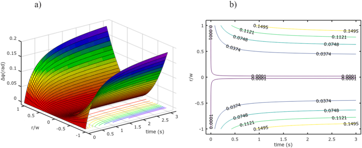
Simulations performed with Eq. (6) in order to show the behavior of the phase difference as a function of space and time variables.
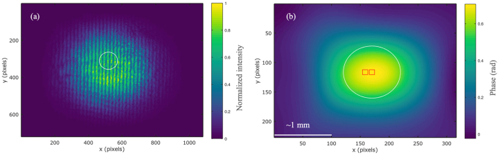
Digital images showing an experimental interferogram (a) captured with the digital camera and its corresponding numerical photothermal phase shifting map (b). The white circle approximately represents the area delimited by the spot of the pump laser, showing that the photothermal phase shifting extends beyond the area delimited by the laser spot. The experimental space scale is given by white line, ∼1 mm.
Band pass filterapplications
Connector type: Standalone low-pass filters with packages will have different connector types for various applications. For example, filters used for low-frequency applications will use a BNC connector and high-frequency applications will use SMA or N-type connector.
Low pass filters can be designed using different topologies depending on the applications. The selection of these topologies determines the input and output impedance of filters suitable for different scenarios. Here are the most common topologies for different impedance scenarios:
Lowpass filter
In this work, we propose an experiment that combines the sensitivity of both thermal lensing and interferometric techniques, for a simple and quick thermal lensing approach based on the parabolic approximation and the Mach Zehnder interferometer. We use this approach to estimate optical absorption and thermal diffusivity coefficients of pure solvents such as ethanol, methanol, and carbon disulfide, verifying experimentally the validity of the approach. The advantages of this approach are mainly related with the simple and quick implementation of the experimental setup, absence of mechanical movements of the sample during the experiment, few parameters for data fitting and good sensitivity for the measurement of the phase shifting difference, which is around λ/4800.
This section collects any data citations, data availability statements, or supplementary materials included in this article.
Band Pass Filters have one pass-band region with insertion loss close to zero and two stop band regions with a maximum attenuation of more than -60 dB (it may vary in different cases and applications)
Bandpass filters are designed to filter a particular range of frequencies and reject other frequency components from the input signal. These filters are used in applications where high selectivity is required and in noisy environments.
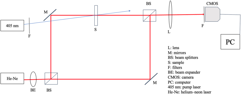
Schematic diagram of the experiment used to validate Eq. (6). The setup is a pump-probe experimental configuration based on the Mach-Zehnder interferometer, where one of their arms is used as a probe beam, while the other is a reference beam. The pump beam is a 405 nm laser diode.
Eq. (6) is only valid inside the region delimited by w, specifically when r/w≪1, and shows a way to experimentally estimate thermal and/or optical parameters of the sample. To analyze the approximation given by Eq. (6), we performed a simple numerical simulation using GNU Octave [18] and taking Δφ0=0.02rad, w=0.5mm, −1
Luis G. Rodriguez: Writing – original draft, Visualization, Validation, Software, Methodology, Investigation, Formal analysis, Data curation, Conceptualization. Joseph Niemela: Writing – review & editing, Project administration, Funding acquisition. Humberto Cabrera: Writing – review & editing, Project administration, Investigation, Formal analysis.
Frequency: operating frequency and cut-off frequency are the important specifications when choosing a low pass filter. Low pass filters can be designed from the kilo-hertz range to the Giga-hertz range.
where A(u) and B(u) are the 2D-FFT of functions a(r) and b(r), respectively. The symbol ⨂ is the convolution product in two dimensions, while u is the inverse space variable, and Δu is the displacement around the center of the inverse space depending on the linear phases.
Authors would like to thank “The Abdus Salam International Centre for Theoretical Physics (ICTP)” for the financial support and in particular the ICTP-SPIE Anchor Research Program.
where P, α, c, ρ and w are the optical power, absorption coefficient, specific heat, density, and waist laser beam, respectively. The radial coordinate is r and the characteristic time constant for the photothermal effect is given by tc=w2/4D, where D=κ/cρ is the thermal diffusivity of the sample, being κ the thermal conductivity. Eq. (1) is deduced by the assumption that all the absorbed energy of a laser beam passing through the sample is fully converted into heat. Also, the model assumes that heat only flows in the radial direction and that thermal convection and radiative effects are both negligible. Considering only the region around the center of the spot of the laser beam, Eq. (1) is reduced to the parabolic approximation of the temperature distribution [6]:
Band pass filterformula
Finally, the photothermal phase shift can be calculated from the argument of the complex function resulting from the ratio between Eq. (10b) and Eq. (10a):
A multi-band RF transceiver system will have multiple antennas to send and receive information using radio waves. If the frequencies are close to each other, it could interfere with other neighboring bands and distort the data. Band pass filters with a specific frequency range ensure it only select the desired frequency spectrum within that operating band.
Pass-band insertion loss: Pass-band insertion loss is very significant in some applications. A good filter should have an insertion loss closer to 0dB (typical).
where φ is given by Eq. (4). The photothermal phase shifting is obtained by using an adaptation of the Takeda's method [19]. The adapted algorithm numerically calculates the two-dimensional Fast Fourier Transform (2D-FFT) of two interferograms that are the digital representation of Eq. (7) and Eq. (8). These 2D-FFT calculations generate three Dirac distributions in the inverse space for each interferogram, which are represented by the following equations:
Band pass filtercircuit
Notice that, the theoretical model given by Eq. (6) is based on the assumptions that the thermal lensing is a perfect thin lens with no aberration, that the temperature distribution is approximately parabolic and that there is no radiative process. However, the theoretical-experimental approach is simpler to use and to implement than other models because fewer experimental parameters are needed to be accurately specified during the experimental data fitting. Additionally, the estimation of optical absorption and/or thermal diffusivity of the sample is almost immediate and direct. Moreover, the experimental variables such as reflections of the cell walls, mode-mismatches of the pump-probe waists, optimal sample z-position, critical sample-detector distance, optimal pinhole size, experimental set-up geometry and the Rayleigh parameter are not required by Eq. (6) and the procedure given in this work. This approach can be also an interesting alternative for measuring two-photon absorption coefficients and nonlinear refractive index, a work is progressing in this direction.
where λ is the wavelength and L the optical path length of the sample. We define the phase difference as the radial variation of the photothermal phase shifting around the laser beam axis. Specifically, the phase difference between points r=0 and r≪w is given by:
By substituting Eq. (2) and Eq. (3) in Eq. (4), and then using this result in Eq. (5), we obtain a simplified expression for the phase difference based on the parabolic approximation:
From Eq. (9a) and Eq. (9b), one of the Dirac delta distributions is selected, for example B(u)(u+Δu) and {FFT[e−iφ]⨂B(u)}(u+Δu), and spatially shifted to the center of the inverse space; by applying the inverse 2D-FFT on these selected distributions the algorithm generates:
where i=−1, a(r) and b(r) are respectively intensity distributions related with the background and the fringe visibility of the interferogram, and φ1 and φ2 are the linear phases of each laser beam arm that forms part of the interferometer.
RF filter solutions play an important role in improving the quality of the received signals by avoiding (filtering out) unnecessary frequency components from the received spectrum. This is significant at the receiving end since the signal strength is often too low at the receivers. Any noise could potentially impact the received signal quality and thus information loss.
Secure .gov websites use HTTPS A lock ( Lock Locked padlock icon ) or https:// means you've safely connected to the .gov website. Share sensitive information only on official, secure websites.
Form factor/package size: filter solutions are available in various sizes and shapes from SMD components to inches-long solid packages. Low pass filters used in mobile devices are miniaturized size; applications like base stations will have to use high power handling filters (which increases the size).
Theoretical and experimental values of the parameters used and estimated in the experiment. The pump wavelength is λe=405nm, and the probe wavelength is λp=633nm. The pump beam radius is w≅0.49m.
Passive low-pass filters can be created using different methods. Microstrip lines with varying impedance are used to design low-pass filters in the microwave frequency range. One of the simplest ways is using the LC combination.
The photothermal effect can be produced when a laser beam impinges on a sample and due to optical absorption, results in an increase of the localized temperature distribution in the sample around the propagating laser beam axis. For a Gaussian laser beam the temperature distribution [11] is then given by:
Once the experimental data are generated, two separate results are obtained. First, the numerical code described above is used to process the photothermal phase shifting and calculate the phase difference as a function of time for different relative radial positions. This results in a numerical surface such as shown in Fig. 4 for an ethanol sample. As can be seen, the surface shows the typical characteristics of a thermal lensing signal, i.e., the parabolic and inverse dependence of the phase difference on space and time, respectively. At the bottom of Fig. 4, on the r/w-time plane, is possible to observe the experimental level curves which agree well with the ones obtained by numerical simulation of Eq. (6) and shown previously in Fig. 1. The shape of the surface can be understood as a steady state regime for the phase difference after tc is reached. The direct relationship between phase difference and temperature change indicates that the phase difference is almost constant because the heat around the region delimited by w remains unchanged for times greater than tc.
To directly measure the photothermal phase shifting, we use a pump-probe experimental configuration based on Mach-Zehnder interferometer and the respective post-processing numerical analysis of their interferograms [17]. At the exit of the interferometer, the intensity distribution of a typical interference pattern can be written by the following equation:
Stop-band attenuation: Stop-band attenuation is yet another main specification for LPFs. A typical low pass filter will have very good stop band rejection/attenuation depending on the applications (30dB to 80dB).
The authors declare that they have no known competing financial interests or personal relationships that could have appeared to influence the work reported in this paper.
Where φ has been replaced by φ(r,t). As it can be seen in Eq. (11), amplitudes and linear phases have been eliminated, remaining only the photothermal phase shifting.
In Fig. 3 the interferogram and the photothermal phase shift map are represented in false colors as an aid to visualization. In the photothermal phase shifting map, each color-pixel value has its correspondent radian value, for example, the lightest color corresponds to 0.7 rad while the darkest one approximately represents 0 rad. The white circle in the phase map encloses the region delimited by the spot of the pump beam laser at radius of 0.49mm. The red squares represent the areas around r=0 and r≠0 where the photothermal phase shifting is individually estimated by calculating the phase-mean-value of the radian pixel values enclosed inside each square. Subsequently, the phase difference is calculated for a specific time interval. The procedure is repeated for the other interferograms in order to obtain experimental data from Eq. (6).
The approach developed in this work allows for a fast analysis of both optical absorption and thermal diffusivity coefficients of pure solvents by measuring typical experimental variables and fitting a few theoretical parameters. The approach relies on the measurement of the de-phasing occurring in an interference pattern when a photothermal effect is induced by a pump laser beam. We have shown the validity of the approximation and the approach by estimating the optical absorption and thermal diffusion coefficients of pure solvents and comparing them with the values reported in literature. We also show that the approach has an experimental sensitivity of λ/4800, indicating that this approach can be an attractive alternative for the thermo-optical characterization of pure solvents and may be other materials.
Experimental phase difference surface obtained for ethanol after the numerical processing is performed on the digital interferograms.
Wireless technology is inevitable in our daily life. It helps us to increase productivity and offers convenience and a life of ease. However, all these transmitting devices contribute radio frequency noise to their surroundings. It is very challenging to design a device or system without affecting the existing systems.
Band pass filtercalculator
Phase difference as a function of the exposition time for the solvents used in the experiment. Open symbols represent experimental data while continuous lines are the best fittings obtained by means of Eq. (6). The coefficient of determination for the whole set of curves is approximately R2 = 0.99883. Dots indicate the root mean square value of noise (fluctuations) phase differences as a function of time.
Upper cut-off frequency: this is the upper passband frequency point of the filter. After this point, the filter will have more attenuation moving to a higher frequency range.
Lower cut-off frequency: this is the frequency point at which the filter starts to reject lower-frequency components. Any frequency below this point will have higher attenuation than the pass band.
Similar to low-pass filters, high-pass filters also have two regions. A pass-band region allows the high frequency to pass with minimum insertion loss and a stop-band region where it has maximum attenuation or rejection.
In Fig. 5 we also plot a measure of the fluctuations or noise observed during the experiment, in this case, dots represent the root mean square value of the noise which is about 0.6mrad, averaged over the three sets of the experimental data. From this result and using the minimum phase difference of 1.3mrad measured with our experiment, we obtain a sensitivity of λ/4800 for a minimum SNR of approximately 2. It is important to point out that during the experiment current amplifier or photodiode gain are not used to increase the sensitivity of the measurements [26], which means the results are purely optical measurements performed from the induced photothermal phase shifting in the interference pattern. Therefore, the sensitivity of the method favorably compares with the sensitivity achieved by photothermal lens spectroscopy in which loc-kin amplifiers or current amplifiers are used for sensitive measurements.
Highpass filter
Fig. 2 shows a schematic diagram of the experimental set-up, based on thermal lensing and a Mach-Zehnder interferometer, used to validate the approach. The interferometer is formed by two beam splitters and two mirrors which divide and recombine a low power laser beam. With this set-up two separated beam paths are obtained, probe and reference beams, having the advantage that the fringe tilt and fringe spacing of the interferogram can be adjusted by varying the angle between the two beams at the exit of the interferometer. By placing the sample in the path of the probe beam, the optical phase shifting between wavefronts of both beams can be measured. As shown in Fig. 2, a CW Helium–Neon (He–Ne 05-UR-111, Melles Griot) laser beam of 1 mW of optical power and 632.8 nm of wavelength is first collimated to a 6 mm diameter by using a beam expander BE, and split on two beams by means of a fifty-fifty beam splitter BS (BS016, Thorlabs), after reflecting on the mirrors M (Thorlabs PF10-03-G01) both beams are recombined again by means of the second beam splitter, forming in this way the Mach-Zehnder interferometer. One of these beams passes through the sample S and it is used as a probe beam, as was previously mentioned. Due to the low power of this beam (∼1 mW), it is collimation in wide diameter and the thermal and optical properties of the tested sample, the induced photothermal effect is negligible, then, the effect of the probe beam in the induced photothermal phase can be neglected. The sample consists of a pure solvent placed in a quartz cuvette of 2 mm of optical path length (21-Q Quartz Cuvette 2 mm); for this experiment the selected solvents are ethanol, methanol, and carbon disulfide or CS2. A lens L is placed at the exit of the interferometer, in order to image the exit wall of the quartz cuvette on the sensor of the digital camera's CMOS (acA 2440-20gc, Basler). To avoid sensor saturation, reduce noise, and improve the interference contrast, neutral optical density (NEK01S, ND Filter Set) and band-pass optical filters F (FLH05633-5, Bandpass Filter) are placed in front of the camera. The pump beam is produced by a 405 nm laser diode at an optical power of 300 mW (M-33A405-300-G, S-Laser). Due to the high power of the pump beam, it is focused in the sample; its radius at the position of the sample remains approximately constant and our estimations indicate that w≅0.49±0.01mm. This experimental configuration satisfies the assumptions imposed on the theoretical model and any uncertainty in measuring the radius affects the measuring accuracy of the thermal diffusion coefficient. There is a small angle (∼4°) between the probe and pump beams due to the arrangement of the optical components used in the experimental setup, we can use the small-angle approximation. Also, because of the thermal diffusive nature of the photothermal effect, the influence of this small angle on the temperature profile can be neglected, especially when the exposure time are larger enough and the thermal diffusive process become Gaussian.
Temperature range: Low Pass Filters are designed to operate in different temperature ranges. Some components are sensitive to temperature fluctuations, which could affect the filter performance.
Official websites use .gov A .gov website belongs to an official government organization in the United States.
A low pass filter has two regions a pass band region and a stop band region. A typical low pass filter will have low insertion loss across the pass-band region until the cut-off frequency and higher attenuation after the cut-off frequency across the higher frequency range.
Once part of the laser energy is absorbed by the sample and the temperature rise is generated, the localized refractive index of the sample close to the laser beam axis varies producing a lens-like medium known as thermal lensing effect [6]. Correspondingly, the refractive index of the sample is not constant and is dependent of the radial coordinate and the time: n(r,t)=n0+(dn/dT)T(r,t), where n0 is the constant refractive index value in absence of the localized temperature increase, and (dn/dT) is the temperature dependence of the refractive index. The absolute refractive index change can be written as:
Band pass filterPDF
The thermal lensing acts as a lens affecting the propagation of the laser beam, i.e., it generates a localized phase shifting of the laser beam wavefronts at the exit of the sample [6]. This photothermal phase shifting can be given by:
High-pass filters are filters used in RF and wireless applications to reject low-frequency components from a signal and pass the high-frequency range. These filters are used in many applications for frequency selectivity and provide higher isolation from low-frequency components.
A thermal lensing approach based on parabolic approximation and Mach-Zehnder interferometer for measuring optical absorption and thermal diffusivity coefficients in pure solvents is described in this work. The approach combines the sensitivity of both thermal lensing methods and interferometry techniques. The photothermal effect is induced by a pump laser beam generating localized changes in the refractive index of the sample, which are observed as a shift in phase of the interference pattern. Each interference pattern is recorded by means of a digital camera and stored as digital images as a function of time. The images are then numerically processed to calculate the phase shifting map for a specific time. From each phase shifting map, the experimental phase difference as a function of time is calculated giving a phase-time transient, which is fitted to a mathematical model to estimate the optical absorption and thermal diffusivity of the sample. The experimental results show that the sensitivity is approximately λ/4800 for the minimum phase difference measured.
Power handling: Different applications have different power level requirements. It is important to make sure the LPF can handle sufficient power required for specific applications.
I'm Rajiv Baby, a senior application engineer with 15 years of experience in RF Test & Measurement solutions. Interested in Wireless technologies, coding and blogging. Connect with me on LinkedIn
Second, the numerical code also selects experimental points of the phase difference as a function of time for a specific r/w position in a region close to the center of the pump beam spot. These experimental points are represented for the open symbols in Fig. 5, where the curves show the classical thermal lensing transients. In this figure, the continuous lines are the best fits to the data obtained using Eq. (6), where Δφ0 and tc parameters are left freely running during the fitting procedure. As is shown by Eq. (6) these parameters are independent from each other and therefore we can use them to estimate the optical absorption α or the thermal diffusivity D of the sample under study. From the experiment, we measured P and λ for the lasers, and L, κ and (dn/dT) are constants for each sample; by using the value of Δφ0 obtained by the fitting, the optical absorption coefficient α is calculated. On the other hand, if we use the experimentally measured value of w and the fitting value of tc, the thermal diffusivity D of the sample is then estimated, even if the other experimental parameters are unknown. This is possible because in Eq. (6), the first term related to α affects the amplitude and is independent of the second term which is related to the temporal evolution of the phase (tc and D). Table 1 summarizes the thermal constants of the samples used in the experiment, the fitting parameters and the estimations of optical absorption and thermal diffusivity calculated from the experimental results shown in Fig. 5. The estimated values of α and D, given in Table 1, agree well with values reported previously in literature [[20], [21], [22], [23], [24], [25]], also shown in Table 1. Note that, for measurements of the α at a laser wavelength of 405 nm there are no reported values so far. Therefore, our results were only comparable with the nearest measurement value at 460 nm and 532.8 nm [24,25].
The optical power of the pump beam is adjusted by linear neutral density filters placed at the exit of the laser diode and, this allows us to control the intensity level on the sample and to avoid thermal convection effects as well. Due to the large value of w and considering the thermal diffusivity values of the solvents used here, the characteristic relaxation thermal time is expected to be around a half-second. Therefore, the samples are exposed to the radiation of the pump beam for times greater than 1 s. The exposure time is achieved by means of a homemade electronic shutter connected to the diode laser. During the exposure time, a set of thirty photographs per second are taken by the digital camera and recorded in a personal computer where they are post-processed once the experiment is done. During the post-processing, the first photograph of the sequence is the reference interferogram at t=0s, i.e., without any photothermal perturbation. This interferogram is numerically processed by following the method described in the previous section. The next interferogram is also processed with the same algorithm. By using Eq. (11) the photothermal phase shifting for a time interval of 0.033 s is then calculated. The same procedure is performed for the remainder of the interferograms, t>0s. The algorithm to process the interferograms and do the calculations is based on a Takeda's methods [18] and was also implemented on GNU Octave [17]. The results are shown in Fig. 3(a) and (b), plotting respectively, an example of an experimental interferogram and the corresponding photothermal phase shifting map, for 1 s of exposition time.
As the name implies, Low Pass Filters remove (reject) any low-frequency components from the signals. Low pass filters are used in many RF applications for frequency selection and to avoid harmonic signals from the transmitting antennas and power amplifiers.


 Ms.Cici
 8618319014500