
Appendix D: Use of the Microscope - body tube on microscope
The four layer F-DLC coating manufacturing process uses a combination of PVD sputtering and PACVD. The Ti layer is sputtered on the substrate and while the remaining three layers are deposited with PACVD in a vacuum chamber at 250 °C. On the Ti-coated substrate, DLN is deposited by PACVD. Hydro-carbonated DLN gases integrated with silicon and oxygen provide the deposition of a soft DLN (a-C:H:Si:O) layer. Next the DLC layer is deposited in the same environment. Finally, the fluorine precursor in liquid form is introduced to the system which is then vaporized and co-deposited with the final DLC layer at the end of the deposition process yielding a top fluorinated DLC (f-DLC) layer.
Rayleigh scattering is by far the most common transition, due to the fact that no change has to occur in the vibrational state of the molecule. The anti-Stokes transition is the least common, as it requires the molecule to be in a vibrationally excited state before the photon is incident upon it. Due to the lack of intensity of the anti-Stokes signal and filtering requirements that eliminate photons with incident energy and higher, generally only Stokes scattering is used in Raman measurements. The relative intensities of Rayleigh, Stokes and anti-Stokes scattering can be seen in Figure \(\PageIndex{2}\).
This can be illustrated by the following examples. Purified HiPco tubes may be fluorinated at 150 °C to give F-SWNTs with a C:F ratio of approximately 2.4:1. The Raman spectra (using 780 nm excitation) for F-SWNTs shows in addition to the tangential mode at ~1587 cm-1 an intense broad D (disorder) mode at ~ 1295 cm-1consistent with the side wall functionalization. Irrespective of the arrangements of the fluorine substituents, thermolysis of F-SWNTs results in the loss of fluorine and the re-formation of unfunctionalized SWNTs alnog with their cleavage into shorter length tubes. As can be seen from Figure \(\PageIndex{18}\), the intensity of the D-band decreases as the thermolysis temperature increases. This is consistent with the loss of F-substituents. The G-band shows a concomitant sharpening and increase in intensity.
The thermal conductivity of the fabricated multilayer F-DLC sample was measured using time-domain thermoreflectance (TDTR). Details of TDTR measurement are discussed in the “Methods” section. Figure 2a shows the thermal reflectivity change as a function of the time delay \(\varDelta t\) between the pump and probe pulses for the test sample, yielding a thermal conductivity of the coating of \(k\) = 0.46 ± 0.05 W m−1 K−1 by assuming a volumetric heat capacity consistent with previous measurements on DLC materials, \(C=\) 2.5 J cm−3 K−1 18. Due to the limited thermal penetration depth of the TDTR measurement, \(d=\sqrt{k/\pi {Cf}} \sim\)100 nm, we measure the thermal conductivity of the top fluorinated f-DLC layer. As the top f-DLC layer is the most amorphous among all layers due to the fluorination process, it has the lowest thermal conductivity of all layers, ensuring that our measurement represents the lower-bound thermal conductivity of the entire multilayer coating.
We thank Dr. Richard T. Haasch at the Materials Research Laboratory at the University of Illinois for their assistance in XPS characterizations and insightful discussions. M.J.H, L.L, J.M, and N.M. gratefully acknowledge funding support from the Office of Naval Research (ONR) under grant No. N00014-16-1-2625. N.M. also gratefully acknowledges funding support from the International Institute for Carbon Neutral Energy Research (WPI-I2CNER), sponsored by the Japanese Ministry of Education, Culture, Sports, Science and Technology. J.M. gratefully acknowledges funding support from the PPG-MRL assistantship. This research was partially supported by the NSF through the University of Illinois at Urbana-Champaign Materials Research Science and Engineering Center DMR-1720633.
The appearance of D-peak can be interpreted due to the breakdown of the k-selection rule. It also depends on the laser energy and diameter of the SWNTs. This behavior is interpreted as a double resonance effect, where not only one of the direct, k-conserving electronic transitions, but also the emission of phonon is a resonant process. In contrast to single resonant Raman scattering, where only phonons around the center of the Brillouin zone (q = 0) are excited, the phonons that provoke the D-band exhibit a non-negligible q vector. This explains the double resonance theory for D-band in Raman spectroscopy. In few cases, the overtone of the D-band known as the G’-band (or D*-band) is observed at 2600-2800 cm-1, and it does not require defect scattering as the two phonons with q and –q are excited. This mode is therefore observed independent of the defect concentration.
Fluorinated nanotubes may be readily functionalized by reaction with the appropriate amine in the presence of base according to the scheme shown in Figure \(\PageIndex{20}\).
When the Raman spectra of the functionalized SWNTs is taken (Figure \(\PageIndex{21}\)), it is found out that the relative intensity of the disorder D-band at ~1290 cm-1versus the tangential G-band (1500 - 1600 cm-1) is much higher for thiophene-SWNT than thiol-SWNT. If the relative intensity of the D mode is the measure of the level of substitution, it can be concluded that there are more number of thiophene groups present per C than thiol groups. However, from the TGA weight loss data the SWNT-C:substituent ratios are calculated to be 19:1 and 17.5:1. Thus, contrary to the Raman data the TGA suggest that the number of substituents per C (in the SWNT) is actually similar for both substituents.
diamond-like coating for firearms
Raman measurements provide useful characterization of many materials. However, the Raman signal is inherently weak (less than 0.001% of the source intensity), restricting the usefulness of this analytical tool. Placing the molecule of interest near a metal surface can dramatically increase the Raman signal. This is the basis of surface-enhanced Raman spectroscopy (SERS). There are several factors leading to the increase in Raman signal intensity near a metal surface
Ma, X.-H., Zhou, X.-D., Lan, Z., Li, Y.-M. & Zhang, Y. Condensation heat transfer enhancement in the presence of non-condensable gas using the interfacial effect of dropwise condensation. Int. J. Heat Mass Transf. 51, 1728–1737 (2008).
Raman activity depends on the polarizability of a bond. This is a measure of the deformability of a bond in an electric field. This factor essentially depends on how easy it is for the electrons in the bond to be displaced, inducing a temporary dipole. When there is a large concentration of loosely held electrons in a bond, the polarizability is also large, and the group or molecule will have an intense Raman signal. Because of this, Raman is typically more sensitive to the molecular framework of a molecule rather than a specific functional group as in IR. This should not be confused with the polarity of a molecule, which is a measure of the separation of electric charge within a molecule. Polar molecules often have very weak Raman signals due to the fact that electronegative atoms hold electrons so closely.
The standard Raman instrument is composed of three major components. First, the instrument must have an illumination system. This is usually composed of one or more lasers. The major restriction for the illumination system is that the incident frequency of light must not be absorbed by the sample or solvent. The next major component is the sample illumination system. This can vary widely based on the specifics of the instrument, including whether the system is a standard macro-Raman or has micro-Raman capabilities. The sample illumination system will determine the phase of material under investigation. The final necessary piece of a Raman system is the spectrometer. This is usually placed 90° away from the incident illumination and may include a series of filters or a monochromator. An example of a macro-Raman and micro-Raman setup can be Figure \(\PageIndex{5}\) and Figure \(\PageIndex{6}\). A macro-Raman spectrometer has a spatial resolution anywhere from 100 μm to one millimeter while a micro-Raman spectrometer uses a microscope to magnify its spatial resolution.
Search HT. A Feasibility Study of Heat Transfer Improvement in Marine Steam Condensers (Naval Postgraduate School, 1977).
A total of three F-DLC coated substrates consisting of a polished silicon wafer, a Cu tab, and an Al tab were tested in the chamber system for the full-time duration. The condensation conditions of each sample were recorded at least twice a week via visual observation, which has been used in the past to identify the condensation mode (dropwise or filmwise condensation). Due to inherent leaks into the chamber from the pressure difference arising from the atmosphere and the saturated steam at lower pressure, the system had to be shutdown periodically (once every month) in order to vacuum out the chamber and ensure pure saturated conditions. During shutdown, the chamber was not opened and simply was vacuumed to remove non condensables, with shutdown lasting no more than 3 h.
Rose, J. W. Dropwise condensation theory and experiment: a review. Proc. Inst. Mech. Eng. J. Power Energy 216, 115–128 (2002).
Here, we develop a hydrophobic coating synthesis and application approach using multilayer fluorinated diamond-like carbon (F-DLC) that meets all five requirements to enable sustained dropwise condensation of steam. By using scalable co-deposition of a short-chain fluorocarbon with well-established DLC (a-C:H, amorphous hydrogenated carbon films), we demonstrate a hydrophobic coating having surface energy characteristics of non-polar polymers, with a high Young’s modulus approaching that of pure metals. We demonstrate the versatility of F-DLC on a wide range of substrates including crystalline, non-crystalline and common engineering metals, all showing similar surface energy after coating. Multilayer fluorinated diamond-like carbon not only demonstrates enhanced dropwise condensation heat transfer, but also durability in moist environments for a period of more than three years. Characterization of the compatibility of multilayer F-DLC in elevated temperature environments exceeding 300 °C and sustainability after 5000 mechanical abrasion cycles demonstrates thermomechanical resiliency. The outcomes of our work not only develop a low surface energy coating capable of implementation with many potential applications, they overcome barriers to generating hydrophobic surfaces which are resilient to harsh thermomechanical environments in energy production infrastructure.
Raman spectroscopy is a single resonance process, i.e., the signals are greatly enhanced if either the incoming laser energy (Elaser) or the scattered radiation matches an allowed electronic transition in the sample. For this process to occur, the phonon modes are assumed to occur at the center of the Brillouin zone (q = 0). Owing to their one dimensional nature, the Π-electronic density of states of a perfect, infinite, SWNTs form sharp singularities which are known as van Hove singularities (vHs), which are energetically symmetrical with respect to Fermi level (Ef) of the individual SWNTs. The allowed optical transitions occur between matching vHs of the valence and conduction band of the SWNTs, i.e., from first valence band vHs to the first conduction band vHs (E11) or from the second vHs of the valence band to the second vHs of the conduction band (E22). Since the quantum state of an electron (k) remains the same during the transition, it is referred to as k-selection rule.
Carbon nanotubes (CNTs) have proven to be a unique system for the application of Raman spectroscopy, and at the same time Raman spectroscopy has provided an exceedingly powerful tool useful in the study of the vibrational properties and electronic structures of CNTs. Raman spectroscopy has been successfully applied for studying CNTs at single nanotube level.
Sample morphology has also seen to affect the RBMs. The same unfunctionalized sample in different aggregation states gives rise to different spectra. This is because the transition energy, Eii depends on the aggregation state of the SWNTs.
Publisher’s note Springer Nature remains neutral with regard to jurisdictional claims in published maps and institutional affiliations.
A summary of past attempts to achieve durable hydrophobicity shows limited progress to simultaneously achieve low surface energy, high thermomechanical robustness, and durability in pure-steam environments (see Table 1 and Supplementary Table 7). Many studies do not conduct detailed surface characterization after condensation durability tests. While some have reported year-long resiliency to condensation, many of these experiments were not conducted in pure-steam conditions. Instead, atmospheric condensation in the presence of noncondensable gases (NCGs) were used. Condensation in the presence of NCGs is typified by a low condensation rate, and a gentler environment on the coating under test. To clearly demonstrate the effect of accelerated condensation on coating lifespan, we performed a durability study at two different pure-steam vapor pressures devoid of NCGs. The hydrophobic surface exposed to a higher vapor pressure (~25 kPa) failed within 40 min of condensation initiation due to the high condensation rate and harsher environment (see Supplementary Fig. 14). However, the same hydrophobic surface lasted approximately 30 days when exposed to a lower vapor pressure (~2 kPa) and slower condensation rate. Hence, reported coating lifespans for experiments conducted in pure-steam conditions are characteristic of higher condensation rates, and are thus better representations of coating durability. This is stark contrast to condensation longevity studies conducted in the presence of NCGs, which have lower condensation rates, and gentler conditions. When compared to previous approaches, F-DLC represents a synergistic combination of parameters required to achieve robust hydrophobicity (see Table 1 and Supplementary Table 7). The architecture of our F-DLC coating is specifically optimized for the required robustness functionalities such as: strong interfacial toughness, thermal buffering, mechanical robustness, low surface energy, and pinhole prevention. Our 3-year pure-steam condensation durability is the longest reported in literature to date. Furthermore, F-DLC presents a pathway to improve the longevity of low energy coatings in manufacturing, biomedical, and marine applications, owing to its tribological and mechanical properties as well as demonstrated corrosion resistance, biocompatibility, and hemocompatibility32,33,34,35,36,37.
Bonner III, R. W. Dropwise condensation life testing of self assembled monolayers. In Proceedings of the 2010 14th International Heat Transfer Conference. 2010 14th International Heat Transfer Conference. Volume 2, pp. 221–226 (ASME, Washington, DC, USA, 2010).
Rose, J. W. Heat-transfer coefficients, Wilson plots and accuracy of thermal measurements. Exp. Therm. Fluid Sci. 28, 77–86 (2004).
The electronic properties, and therefore the individual transition energies in SWNTs are given by their structure, i.e., by their chiral vector that determines the way SWNT is rolled up to form a cylinder. Figure \(\PageIndex{7}\) shows a SWNT having vector R making an angle θ, known as the chiral angle, with the so-called zigzag or r1 direction.
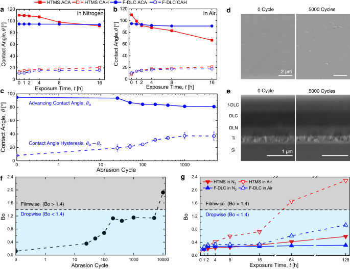
Figure 4d shows time-lapse images of condensation on each sample mounted in the vertical orientation. The images show that condensing droplets on the F-DLC surfaces have clear circular shapes and grew to 3.2–3.5 mm in diameter prior to departing the surface throughout the testing period, which lasted for 3 years (>1095 days). Even after the long-term exposure to saturated steam conditions, the F-DLC coating exhibited continued dropwise condensation during tests, regardless of the base substrate. This was not true for control samples consisting of Cu and Al tabs coated with self-assembled monolayers of (heptadecafluoro-1,1,2,2 tetrahydrodecyl)trimethoxysilane (HTMS), which failed via transition to filmwise condensation after less than one month of testing (see Supplementary Table 4). After exposing to steam for 3 years, the DI water contact angle on the F-DLC coating changed from \({\theta }_{{{{{{\rm{a}}}}}}}/{\theta }_{{{{{{\rm{r}}}}}}}\) = 99.1°/86.2° to \({\theta }_{{{{{{\rm{a}}}}}}}/{\theta }_{{{{{{\rm{r}}}}}}}\) = 70.5°/57.1° (see Supplementary Table 5). As a comparison, we also conducted durability assessment on iCVD coatings (DVB-PFDA films) having different film thicknesses (30 nm and 60 nm) in the same environmental vacuum chamber system (see Supplementary Fig. 7). Both iCVD surfaces showed unstable dropwise condensation (irregular shaped droplets) after 1 week of steam exposure, in agreement with recent work29. See the “Methods” section for details of the HTMS and iCVD hydrophobic surface fabrication.
One tool employed to understand the surface chemistry of noble metal nanomaterial, particularly those composed of gold or silver is surface-enhanced Raman spectroscopy (SERS). Replacing a metal surface with a metal nanoparticle increases the available surface area for the adsorption of molecules. Compared to a flat metal surface, a similar sample size using nanoparticles will have a dramatically stronger signal, since signal intensity is directly related to the concentration of the molecule of interest. Due to the shape and size of the structure, the electrons in the nanoparticle oscillate collectively when exposed to incident electromagnetic radiation. This is called the localized surface plasmon resonance (LSPR) of the nanoparticle. The LSPR of the nanoparticles boosts the Raman signal intensity dramatically for molecules of interest near the surface of the nanoparticle. In order to maximize this effect, a nanoparticle should be selected with its resonant wavelength falling in the middle of the incident and scattered wavelengths.
Miljkovic, N. et al. Jumping-droplet-enhanced condensation on scalable superhydrophobic nanostructured surfaces. Nano Lett. 13, 179–187 (2013).
Deposition of polymeric PFDA and DVB-PFDA films were performed via iCVD in a stainless-steel vacuum chamber with a base pressure of 5 mTorr, using 1H,1H,2H,2H-Perfluorodecyl acrylate (PFDA, Sigma-Aldrich, CAS#:27905-45-9) as the monomer, Divinyl benzene (DVB, Sigma-Aldrich, CAS#:1321-74-0) as the crosslinker and Tert-Butyl Peroxide (TBPO, Sigma-Aldrich, CAS#:110-05-4) as the initiator. No surface treatments were applied to the surface pre or post deposition. During deposition the chamber pressure was maintained at 300 mTorr using a throttle valve. The substrate and filament temperatures were kept constant at 20 °C and 280 °C, respectively, during the deposition process. The delivery of the precursor vapors into the chamber was controlled by a set of needle valves and the depositions were performed at flowrates of 1.7, 1.6 and 1.2 sccm for PFDA, DVB and TBPO, respectively. The thickness of the samples was monitored real-time using a laser interferometry system mounted on the vacuum chamber and the depositions were stopped when the target thicknesses of 30 nm or 60 nm were reached.
Polished aluminum and copper tabs were first ultra-sonicated in acetone (10 min), followed by IPA (10 min), then thoroughly rinsed in DI water and dried under a clean N2 gas stream. To fabricate the hydrophobic surface, the Al and Cu tabs were functionalized with (heptadecafluoro-1,1,2,2 tetrahydrodecyl)trimethoxysilane (HTMS, TCI America, CAS #: 83048-65−1) using the vapor phase deposition method47. Briefly, the substrates were placed in a glass beaker with a vial of HTMS toluene solution (5% v/v). A glass lid was placed on top to seal the container, followed by heating in atmospheric pressure oven (Thermo Scientific, Lindberg Blue M) at 80 ± 5 °C for 3 h to allow conformal HTMS SAM deposition.
Roy, R. K. & Lee, K. R. Biomedical applications of diamond-like carbon coatings: a review. J. Biomed. Mater. Res. B Appl. Biomater. 83, 72–84 (2007).
Furthermore, TDTR measurements of the 3-year tested F-DLC samples show insignificant change (<1%) in the thermal conductivity (see Supplementary Table 5). Even after 3 years of condensation, the F-DLC coatings demonstrate the capacity to maintain comparable droplet mobility and thermal conductivity. As a result, the heat transfer performance remains similar when compared to fresh F-DLC surfaces (see Supplementary Fig. 9).
As discussed above, the presence of a significant D mode has been the primary method for determining the presence of sidewall functionalization. It has been commonly accepted that the relative intensity of the D mode versus the tangential G mode is a quantitative measure of level of substitution. However, as discussed below, the G:D ratio is also dependent on the distribution of substituents. Using Raman spectroscopy in combination with XPS analysis of F-SWNTs that have been subjected to thermolysis at different temperatures, a measure of the accuracy of Raman as a quantitative tool for determining substituent concentration can be obtained. As can be seen from Figure \(\PageIndex{19}\), there is essentially no change in the G:D band ratio despite a doubling amount of functional groups.Thus, at low levels of functionalization the use of Raman spectroscopy to quantify the presence of fluorine substituents is a clearly suspect.
Vosough, A. et al. Improvement power plant efficiency with condenser pressure. Int. J. Multidiscip. Sci. Eng. 2, 38–43 (2011).
Prior to thermal conductivity measurement, the sample was coated with a 111 ± 2 nm-thick Al film by magnetron sputtering (AJA Orion3 Sputter Coater). It was assumed that the film was free of adsorbed water because the sputtering procedure involved pumping the sputter chamber down to \(\approx\)1.33 × 10⁻⁵ Pa. The TDTR system uses a mode-locked Ti:sapphire laser tuned to 785 nm and a repetition rate of 74.6 MHz9. The output laser was split into separate pump and probe beams by a polarizing beam splitter. The power of the pump beam was set to 10 mW, and the probe beam power was set to 5 mW. The intensity of the pump beam was modulated with an electro-optic modulator at \(f=\)10.1 MHz synchronized with an RF lock-in amplifier. The time delay of the arrival of the pump and probe beam to the surface was adjusted by a mechanical delay stage in the path of the probe beam. The pump and probe beams were overlapped on the sample and the beams were focused using a 5× objective lens. The laser spot size was ≈ 10.7 µm. A photodiode was used to detect the reflected probe beam and the light from the pump beam was blocked from reaching the detector by spatial filtering and two-tint wavelength filtering. The signal was measured by a lock-in amplifier connected to the photodiode. The thickness of F-DLC (\(1.65\pm 0.05\) µm) is measured by cross-section SEM imaging. \(\sqrt{kC}=\left(1.07\pm 0.05\right)\times {10}^{-3}\)(W s1/2)/(m K). The heat capacity of amorphous carbon film is usually within the rage of 2.5 J/(cm3 K)44, hence the thermal conductivity of the film \(k=0.46\pm 0.05\) W/(m K). The error comes from experimental uncertainty (~10%).
Nature Communications thanks Xiao-Dong Wang, Xianming Dai, Qi Zhao and the other, anonymous, reviewer(s) for their contribution to the peer review of this work.
Functionalization of SWNTs leads to variations of relative intensities of RBM compared to the starting material (unfunctionalized SWNTs). Owing to the diameter dependence of the RBM frequency and the resonant nature of the Raman scattering process, chemical reactions that are sensitive to the diameter as well as the electronic structure, i.e., metallic or semiconducting of the SWNTs can be sorted out. The difference in Raman spectra is usually inferred by thermal defunctionalization, where the functional groups are removed by annealing. The basis of using annealing for defunctionalizing SWNTs is based on the fact that annealing restores the Raman intensities, in contrast to other treatments where a complete disintegration of the SWNTs occurs. Figure \(\PageIndex{11}\) shows the Raman spectra of the pristine, functionalized and annealed SWNTs. It can be observed that the absolute intensities of the radial breathing modes is drastically reduced after functionalization. This decrease can be attributed to vHs, which themselves are a consequence of translational symmetry of the SWNTs. Since the translational symmetry of the SWNTs is broken as a result of irregular distribution of the sp3-sites due to the functionalization, these vHs are broadened and strongly reduced in intensity. As a result, the resonant Raman cross section of all modes is strongly reduced as well.
Though Raman spectroscopy has provides an exceedingly important tool for characterization of SWNTs, however, it suffers from few serious limitations. One of the main limitations of Raman spectroscopy is that it does not provide any information about the extent of functionalization in the SWNTs. The presence of D-band indicates disorder, i.e. side wall distribution, however it cannot differentiate between the number of substituents and their distribution. Following are the two main limitations of Raman Spectroscopy:
Although our work demonstrates high durability for small-scale F-DLC surfaces (~0.1 m), the overall life cycle cost (LCC) $/m2/yr remains reasonable. When compared to a conventional SAM hydrophobic coating (~$800/m2/yr), the LCC of F-DLC (~$1400/m2/yr) is ~72% higher but shows remarkable durability and offers a promising payback period (see Supplementary Note 11 for detailed economic assessment). We are currently collaborating with Abbott Power Plant at the University of Illinois to develop a larger-scale (tube length of ~0.6 m) condenser prototype that will undergo testing in the power plant environment with higher steam pressure (>100 kPa) and temperature (>100 °C). We acknowledge that this prototype is still not on an industrial scale, but our F-DLC deposition process, which combines PVD and PACVD in the same vacuum system, presents scalability and cost reduction opportunities. Due to the large global physical vapor deposition (PVD) market size, PVD manufacturing can significantly reduce coating costs when scaled up41. Additionally, in many applications, compact heat exchanger design is crucial, particularly in nuclear power plants, submarines, and navy ships. For these applications, the efficiency, reduced weight-volume and extended durability are of utmost importance, as opposed to cost42,43. Thus, F-DLC-coated compact and durable heat exchangers are promising.
The F-DLC coating provides a conformal, pinhole free, adherent solution for the rational design of multiple layers that can enable enhanced condensation heat transfer (Fig. 3). The demonstrated condensation heat transfer results are not unique, showing similar performance with previously developed hydrophobic materials5,21,27,28. However, the potential durability of F-DLC when compared to classical hydrophobic coatings makes it beneficial. To evaluate the long-term durability of the F-DLC coating during steam condensation, we built a separate vacuum-compatible condensation chamber (Fig. 4a, b). To accelerate the condensation process and increase the condensation heat flux, the testing samples were mounted on an aluminum cold plate (Fig. 4c) and placed in the custom-built environmental chamber commissioned in 2017. The environmental chamber was first evacuated to \(P\) < 5 Pa to remove noncondensable gases, then, hot steam was injected into the chamber from a boiler after following a detailed degassing procedure. Cold water at ~10 °C was supplied to the cold plate inlet via a chiller, which reduces the surface temperature of the mounted samples. As the steam comes in contact with the F-DLC surfaces it forms water droplets and initiates dropwise condensation. Due to the good droplet mobility on the hydrophobic F-DLC surfaces, the condensed water droplets shed from the surface toward the condensate collector at the bottom of the chamber and finally the condensate returns to the boiler by gravity. During the long-term test, the chamber pressure ranged from 2 to 3 kPa. For details of the chamber, control systems, and operational procedure, see Supplementary Note 5.
Out of all Raman modes observed in the spectra of SWNTs, the radial breathing modes are unique to SWNTs. They appear between 150 cm-1 < ωRBM < 300 cm-1 from the elastically scattered laser line. It corresponds to the vibration of the C atoms in the radial direction, as if the tube is breathing (Figure \(\PageIndex{9}\)). An important point about these modes is the fact that the energy (or wavenumber) of these vibrational modes depends on the diameter (d) of the SWNTs, and not on the way the SWNT is rolled up to form a cylinder, i.e., they do not depend on the θ of the tube.
Diamond-likecarbondriver
Ma, J., Cha, H., Kim, M.-K., Cahill, D. G. & Miljkovic, N. Condensation induced delamination of nanoscale hydrophobic films. Adv. Funct. Mater. 29, 1905222 (2019).
Thank you for visiting nature.com. You are using a browser version with limited support for CSS. To obtain the best experience, we recommend you use a more up to date browser (or turn off compatibility mode in Internet Explorer). In the meantime, to ensure continued support, we are displaying the site without styles and JavaScript.
Sett, S. et al. Stable dropwise condensation of ethanol and hexane on rationally designed ultrascalable nanostructured lubricant-infused surfaces. Nano Lett. 19, 5287–5296 (2019).
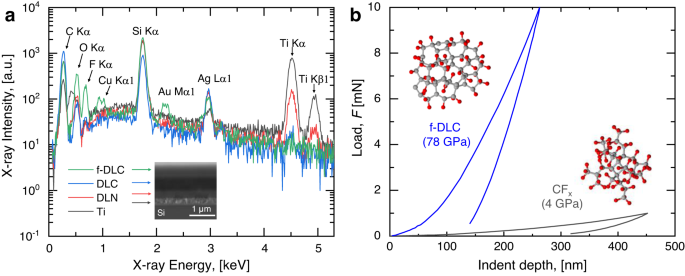
To evaluate and compare the elastic properties, nanoindentation (Hysitron TI 950 TriboIndenter) was performed on both the F-DLC multilayer coating and a control sample consisting of an amorphous carbon-fluorine (CFx) film of equivalent thickness. The depth of the indent was controlled by the applying force from the indenting tip (Berkovich TI-0039 standard tip, Bruker) to the samples. As shown in Fig. 1b, the F-DLC coating shows a ~20× higher Young’s modulus when compared to amorphous carbon-fluorine materials. Additional details of the material fabrication, cross-sectional SEM, and EDS analysis are included in the “Methods” section.
The presence of D-band cannot be correlated to the presence of various defects (such as hetero-atoms, vacancies, heptagon-pentagon pairs, kinks, or even the presence of impurities, etc). Following are the two main characteristics of the D-band found in carbon nanotubes:
Qualitative chemical element analysis for each layer of the F-DLC coating was conducted with EDS (JEOL JSM 7000 F Analytical SEM/EDS). The accelerating voltage was set to 10 kV during the analysis.
Ma, J., Cahill, D. G. & Miljkovic, N. Condensation induced blistering as a measurement technique for the adhesion energy of nanoscale polymer films. Nano Lett. 20, 3918–3924 (2020).
Edmund Rolls. Additional Information. Share This. Oxford Centre for Computational Neuroscience. Speaker. Recent Research. Recent News. Recent Media.
Hakovirta, M., Vuorinen, J. E., He, X. M., Nastasi, M. & Schwarz, R. B. Heat capacity of hydrogenated diamond-like carbon films. Appl. Phys. Lett. 77, 2340–2342 (2000).
Preston, D. J., Mafra, D. L., Miljkovic, N., Kong, J. & Wang, E. N. Scalable graphene coatings for enhanced condensation heat transfer. Nano Lett. 15, 2902–2909 (2015).
Designing a suitable hydrophobic coating is the main challenge to deploying dropwise condensation in real power systems. To overcome this challenge, five coating requirements need to be met simultaneously (Supplementary Fig. 1). (1) The coating needs to be fabricated scalably and must be applicable to a variety of potential substrate materials. Typical condensers in a power station are fabricated from different metals or metal alloys depending on the region, and they are relatively large (~10 m) often containing thousands of tubes in a bundle. (2) The coating needs to be thin (<5 μm) so that the coating parasitic thermal resistance does not off-set the benefit of high dropwise condensation heat transfer8. (3) The coating needs to resist delamination caused by the condensate capillary force. Specifically, condensation-induced blistering, which is the most direct coating degradation mechanism, enables condensate penetration between the interface of the coating through surface defects. This penetration causes localized pressure, and gradually results in complete coating delamination9. (4) The coating must be thermally stable at elevated temperature environments. (5) The coating needs to resist mechanical abrasion during condenser fabrication, assembly, maintenance, and operation. Classical artificial hydrophobic materials such as low surface energy polymers cannot meet these requirements and cannot be utilized due to their low elastic modulus, and poor thermal and mechanical stability.
The large van der Waals interactions between the CNTs lead to an agglomeration of the tubes in the form of bundles or ropes. This problem can be solved by wrapping the tubes in a surfactant or functionalizing the SWNTs by attaching appropriate chemical moieties to the sidewalls of the tube. Functionalization causes a local change in the hybridization from sp2 to sp3 of the side-wall carbon atoms, and Raman spectroscopy can be used to determine this change. In addition information on length, diameter, electronic type (metallic or semiconducting), and whether nanotubes are separated or in bundle can be obtained by the use of Raman spectroscopy. Recent progress in understanding the Raman spectra of single walled carbon nanotubes (SWNT) have stimulated Raman studies of more complicated multi-wall carbon nanotubes (MWNT), but unfortunately quantitative determination of the latter is not possible at the present state of art.
To demonstrate versatility, we deposited F-DLC on a variety of substrates, showing substrate-independent wetting. The wettability of the F-DLC coated substrates were determined by performing water contact angle measurements using a microgoniometer (MCA-3, Kyowa Interface Science). The apparent advancing contact angle on an F-DLC coated smooth silicon wafer (University Wafer) is, \({\theta }_{{{{{{\rm{a}}}}}}}=\)97.5 ± 1.0° (Fig. 2e). Figure 2e shows the apparent advancing (\({\theta }_{{{{{{\rm{a}}}}}}}\)) and receding (\({\theta }_{{{{{{\rm{r}}}}}}}\)) contact angles of water on a wide variety of F-DLC coated substrates. A slight variation in the apparent advancing contact angle (\({\theta }_{{{{{{\rm{a}}}}}}}\)), and contact angle hysteresis (\(\Delta \theta={\theta }_{{{{{{\rm{a}}}}}}}-{\theta }_{{{{{{\rm{r}}}}}}}\)) among the substrates occurred due to the variability in topological homogeneity (roughness) of the surfaces20. Surface roughness homogeneity also affects the droplet distribution and droplet shapes during water droplet condensation. Figure 2f shows top-view optical microscopy images of atmospheric water vapor condensation on the different F-DLC coated substrates demonstrating spherical droplet morphologies with highly mobile contact lines, key to attaining high quality hydrophobicity. Additional details of the condensation experiment can be found in the “Methods” section.
The cause of the vibration is also mechanistically different between IR and Raman. This is because the two operate on different sets of selection rules. IR absorption requires a dipole moment or change in charge distribution to be associated with the vibrational mode. Only then can photons of the same energy as the vibrational state of molecule interact. A schematic of this can be seen in Figure \(\PageIndex{3}\).
Adera, S. et al. Enhanced condensation heat transfer using porous silica inverse opal coatings on copper tubes. Sci. Rep. 11, 10675 (2021).
Yang, Z., W, Y.-Z., Ye, Y.-F., Gong, M.-G. & Xu, X.-L. A simple way to fabricate an aluminum sheet with superhydrophobic and self-cleaning properties. Chin. Phys. B 21, 126801 (2012).
All data that support the findings of this study are available in the manuscript and in the Supplementary information section. Raw data are available from the corresponding authors upon request.
Due to the demonstrated F-DLC conformity, low surface energy, and good thermal conductivity compared to polymeric hydrophobic coatings, the F-DLC coating has high potential to enhance condensation heat transfer performance. To determine the overall condensation heat transfer performance, an F-DLC coated copper (Cu) tube was fabricated following the same process described for the flat coupons and condensation heat transfer experiments were performed in a chamber with a controlled environment (Fig. 3a and Supplementary Fig. 3). Condensation heat transfer behavior and condensate shedding were benchmarked by comparison to an uncoated Cu tube sample having identical diameter and length. Prior to performing the experiments, the water vapor supply was boiled, and the test chamber was evacuated to a pressure \(P\) < 1 Pa to eliminate noncondensable gases and diffusional mass transfer resistances, key to obtaining high fidelity measurements21,22,23,24. Throughout the experiments, the chamber pressure and temperature were continuously monitored to ensure saturated conditions. The temperature of the sample tubes was independently controlled via a cooling loop, and the inlet and outlet tube temperatures were measured using high accuracy resistance temperature detectors to determine the coolant enthalpy change and relate it to the measured condensation heat flux. For all experiments, the cooling water inlet temperature was kept constant at 7 ± 1 °C with a coolant flow rate of 8.0 ± 0.2 L min−1, resulting in fully turbulent internal flow with Reynolds number, \({{{{{{\rm{Re}}}}}}}_{{{{{{\rm{D}}}}}}}\) = 24,000. Condensation heat transfer performance was tested within the vapor pressure range of 3.5 <\({P}_{{{{{{\rm{v}}}}}}}\) < 10.0 kPa, which are common conditions used for condensers in steam-cycle power generation applications25,26. For full details regarding the experimental facility, test protocols, and full uncertainty propagation analysis, refer to Supplementary Notes 4a, 4b, and 4c.
The LibreTexts libraries are Powered by NICE CXone Expert and are supported by the Department of Education Open Textbook Pilot Project, the UC Davis Office of the Provost, the UC Davis Library, the California State University Affordable Learning Solutions Program, and Merlot. We also acknowledge previous National Science Foundation support under grant numbers 1246120, 1525057, and 1413739. Legal. Accessibility Statement For more information contact us at info@libretexts.org.
Dostal, V., Hejzlar, P. & Driscoll, M. J. The supercritical carbon dioxide power cycle: comparison to other advanced power cycles. Nucl. Technol. 154, 283–301 (2006).
In summary, our developed multilayer F-DLC coating has low surface energy characteristic of non-polar polymers, with a high Young’s modulus approaching that of metals. We demonstrate the versatility of F-DLC on a wide range of substrates including crystalline, non-crystalline and common engineering metals, all showing similar surface energy after coating. The F-DLC not only demonstrates enhanced dropwise condensation heat transfer, but also durability in moist environments for a period of more than 3 years. Characterization of the compatibility of F-DLC in elevated temperature environments exceeding 300 °C and sustainability after 5000 mechanical abrasion cycles demonstrates resiliency. The outcomes of our work not only develop a low surface energy coating capable of implementation for a plethora of versatile applications, it overcomes the challenge of generating hydrophobic surfaces that can achieve extended lifetime during exposure to harsh thermomechanical environments. Furthermore, F-DLC coatings have the potential to enhance the sustainability of non-renewable energy generation sources, thus helping societies reach their climate change goals through carbon emissions reduction and lower utilization of environmentally harmful fossil fuels.
To craft durable hydrophobic coatings, past strategies have generally focused on optimizing the coating geometric and structural design. By doing so, these have demonstrated that coating robustness can be enhanced by surface structures which act as a protective or sacrificial armor10,11,12. However, these hierarchical protective structures make the overall coating thick (>10 μm), not suitable for condenser applications. Thus far, little progress has been made to enhance the coating intrinsic properties to overcome the durability challenge.
While the Ti-DLC-f-DLC multilayer focuses primarily on blistering and delamination, satisfying abrasion resistance and high temperature stability requires further stack modification. In addition to the aforementioned three-layer design, we included an additional layer composed of co-deposited DLC and silica (a-C:H:Si:O, amorphous hydrogenated carbon films containing silicon and oxygen) between the DLC layer and the Ti adhesion layer, which we term DLN. The added DLN layer is well-adapted in conventional DLC multilayers to: (1) enhance adhesion with the Ti layer by silica infusion, (2) provide good thermal stability and act as a stress reliever, and (3) further decrease the pinhole density. As a result, the multilayer F-DLC coating designed here not only promises reliable adhesion between the coating and a variety of arbitrary substrates, it also decreases interfacial stresses from abrasion or thermal expansion by increasing the numbers of layered interfaces. We note again that f-DLC represents the top fluorinated DLC layer while F-DLC represents the entire multilayer coating including the Ti, DLN, DLC, and f-DLC layers.
Interestingly, a coating material which can potentially achieve the required coating intrinsic properties for steam condensation applications is diamond-like carbon (DLC). The intrinsic properties of DLC thin films give them the desired mechanical and thermal stability, which are strongly related to the hybridization of sp2 and sp3 carbon bonding13,14,15. Moreover, the abrasion resistance and corresponding interfacial adhesion of DLC coatings can be enhanced by adapting multilayer designs16,17. However, the utilization of such structures for phase-change heat transfer has been under-explored. Specifically, a literature review (included in Supplementary Note 2) reveals that the majority of the past studies have explored tribological, medical, mechanical, wettability, and dielectric property improvement with a focus on altering the fabrication method, recipe modification, and doping. Limited focus has been placed on substrate versatility, or the long-term sustainability of enhanced properties (see Supplementary Table 1). Furthermore, no past study has synergistically considered the crucial parameters required to achieve robust hydrophobic coating design or demonstrated continual dropwise condensation under sustained long-term (>3 year) steam exposure.
DLC coating thickness
XPS was performed using a monochromatic Al Kα-source (Kratos Axis Ultra, Kratos Analytical). The size of the source beam was 2 mm × 2 mm, and the size of the analyzed region was 0.3 mm × 0.7 mm. The instrument was maintained at a pressure of 10−7 Pa during the experiments. The spectra were post processed with CasaXPS software to determine the change in composition of the sample surfaces.
Since D-peak appears due to the presence defects, an increase in the intensity of the band is taken as a fingerprint for successful functionalization. But, whether D-band intensity is a measure of degree of functionalization or not is still sure. So, it is not correct to correlate D-peak intensity or D-peak area to the degree of functionalization. From Figure \(\PageIndex{17}\), it can be observed that for lower degree of functionalization, intensity of the D-band scales linearly with defect density. As the degree of functionalization is further increased, both D and G-band area decrease, which is explained by the loss of resonance enhancement due to functionalization. Also, normalization of the D-peak intensity to the G-band in order to correct for changes in resonance intensities also leads to a decrease for higher densities of functional groups.
Raman spectroscopy observes the change in energy between the incident and scattered photons associated with the Stokes and anti-Stokes transitions. This is typically measured as the change in the wavenumber (cm-1), from the incident light source. Because Raman measures the change in wavenumber, measurements can be taken using a source at any wavelength; however, near infrared and visible radiation are commonly used. Photons with ultraviolet wavelengths could work as well, but tend to cause photodecomposition of the sample.
The tangential modes are the most intensive high-energy modes of SWNTs and form the so-called G-band, which is typically observed at around 1600 cm-1. For this mode, the atomic displacements occur along the cicumferential direction (Figure \(\PageIndex{12}\)). Spectra in this frequency can be used for SWNT characterization, independent of the RBM observation. This multi-peak feature can, for example, also be used for diameter characterization, although the information provided is less accurate than the RBM feature, and it gives information about the metallic character of the SWNTs in resonance with laser line.
The mechanical properties of DLC-like materials are strongly related to the hybridization of sp2 and sp3 carbon bonding. To quantitatively measure the carbon composition of the top layer, we used X-ray photoelectron spectroscopy (XPS, Fig. 2b). The main peak of the C1s spectrum was decomposed into three components: the sp3 (C–C) bond at 285.2 eV, the sp2 (C=C) bond at 284.4 eV and the C–O or C=O bonds at 286.6 eV. We did not observe noticeable amounts of C-Si bonding, which should be located at ~283 eV. The area of the decomposed peaks indicates that relative content of the sp3 and sp2 bonds is 47 ± 10% and 35 ± 10%, respectively, where the uncertainties were calculated from the uncertainty of the sp2 peak position (0.1 eV). The relative content result indicates that although the top layer contains fluorine, the carbon bonding structure does not deviate appreciably from typical DLC materials and maintains a high Young’s modulus and hardness (Fig. 1a). The F1s spectrum showed that most fluorine atoms are bonded with carbon by covalent and semi-ionic C–F bonds. Additional details of the XPS analysis are included in the Methods Section.
To characterize the effects of potential oxidation in non-inert (atmospheric pressure) conditions, identical experiments were also conducted in an atmospheric pressure oven (Lindberg/Blue M Moldatherm Box Furnace). The thermal stability of the F-DLC coating was compared to a control sample consisting of a HTMS SAM hydrophobic coating deposited on identical substrates. As shown in Fig. 5a, b, the F-DLC coating maintains consistent hydrophobicity up to 300 °C exposure temperatures both in N2 and air environments, with air exposure creating slight degradation in hydrophobicity due to substrate oxidation. However, on the HTMS coated control samples, 300 °C exposure resulted in complete degradation (hydrophilicity) after 2 h of heating due to silane desorption. In the inert N2 environment, the F-DLC coating maintained continual hydrophobicity up to 450 °C (Supplementary Fig. 10a, b). In air at 350 °C (Supplementary Fig. 10c) and 400 °C (Supplementary Fig. 10d), F-DLC degrades at a similar rate for 2 h of heating time. Then, at later times (>2 h), the oxidation rate was observed to significantly accelerate for the 400 °C case. For transient applications, where the temperature cycles through high and low setpoints, our F-DLC coating showed excellent durability and low thermomechanical stress (Supplementary Fig. 11).
The surface energy was measured by the contact angle method19 using Fowkes theory and the Young-Dupre equation45. The dispersive, \({E}^{{{{{{\rm{d}}}}}}}\) and polar, \({E}^{{{{{{\rm{p}}}}}}}\) components of the free surface energy were determined by measuring the intrinsic advancing contact angle between the surface and two test liquids with known surface energy components. A non-polar test liquid, diiodomethane was first used to obtain the dispersive component, \({E}^{{{{{{\rm{d}}}}}}}\), where the polar component, \({E}^{{{{{{\rm{p}}}}}}}\) is negligible. Then, deionized (DI) water was used to obtain the polar component, \({E}^{{{{{{\rm{p}}}}}}}\) with known dispersive component, \({E}^{{{{{{\rm{d}}}}}}}\) from the previous measurement. All apparent contact angles were measured using a microgoniometer (MCA-3, Kyowa Interface Science).
Qahtan, T. F., Gondal, M. A., Alade, I. O. & Dastageer, M. A. Fabrication of water jet resistant and thermally stable superhydrophobic surfaces by spray coating of candle soot dispersion. Sci. Rep. 7, 7531 (2017).
Most of the characteristic differences that distinguish the Raman spectra in SWNTs from the spectra of graphite are not so evident for MWNTs. It is because the outer diameter for MWNTs is very large and the ensemble of CNTs in them varies from small to very large. For example, the RBM Raman feature associated with a small diameter inner tube (less than 2 nm) can sometimes be observed when a good resonance condition is established, but since the RBM signal from large diameter tubes is usually too weak to be observable and the ensemble average of inner tube diameter broadens the signal, a good signal is not observed. However, when hydrogen gas in the arc discharge method is used, a thin innermost nanotube within a MWNT of diameter 1 nm can be obtained which gives strong RBM peaks in the Raman spectra.
Aug 16, 2023 — The objective lens magnifies the specimen to provide high magnification levels, with most microscopes having a few objective lenses of different ...
Position your laser spot with unprecedented speed, precision and stability. Choose Aerotech's galvo scanner solutions for high-precision laser processing, and ...
Muhammad Jahidul Hoque, Longnan Li, Jingcheng Ma, Hyeongyun Cha, Soumyadip Sett, Xiao Yan, Kazi Fazle Rabbi, Jin Yao Ho, Siavash Khodakarami, Wentao Yang & Nenad Miljkovic
Molian, P. A., Janvrin, B. & Molian, A. M. Laser chemical-vapor deposition of fluorinated diamond thin-films for solid lubrication. Wear 165, 133–140 (1993).
Diamond like carbonreview
Cao, L., Liu, J., Wan, Y. & Pu, J. Corrosion and tribocorrosion behavior of W doped DLC coating in artificial seawater. Diam. Relat. Mater. 109, 108019 (2020).
DLC coating near me
The overall intensity enhancement of SERS can be as large as a factor of 106, with the surface plasmon resonance responsible for roughly four orders of magnitude of this signal increase. The other two orders of magnitude have been attributed to chemical enhancement mechanisms arising charge interactions between the metal particle and the adsorbate or from resonances in the adsorbate alone, as discussed above.
We conducted XPS analysis on the tested samples to investigate the surface chemistry change after 3 years of steam condensation. The results show that the content of fluorine in the top f-DLC layer reduced from 9.5% to 4.9% during the 3-year test (see Supplementary Table 5), which indicates that the surface energy increases during prolonged exposure to steam and condensation, thus reducing the apparent contact angle. We also performed condensation experiments and analyzed the condensate droplet departure size variation on both fresh and 3-year condensation tested F-DLC surfaces (see Supplementary Fig. 8). The 3-year tested samples showed a 25% increase in the droplet departure size when compared to the fresh F-DLC coating. However, the tested F-DLC surfaces still maintain a low droplet Bond number (\({{{{{\rm{Bo}}}}}}={R}_{{{{{{\rm{f}}}}}}}^{2}/{l}_{{{{{{\rm{y}}}}}}}^{2}\), where \({R}_{{{{{{\rm{f}}}}}}}\) is the characteristic lateral length of the liquid droplet, taken to be its final equilibrium radius immediately before departure, and \({l}_{{{{{{\rm{y}}}}}}}\) is the capillary length) representing the ratio of equilibrium droplet radius immediately before departure to capillary length scale of water. The \({{{{{\rm{Bo}}}}}}\) number mediated dropwise-to-filmwise transition occurs at \({{{{{{\rm{Bo}}}}}}}_{{{{{{\rm{crit}}}}}}}=1.4\), with \({{{{{\rm{Bo}}}}}} > 1.4\) predicting gravitationally dominated puddle formation and filmwise condensation20. Calculations of \({{{{{\rm{Bo}}}}}}\) for each 3-year tested F-DLC surface, based on the final surface contact angle measurement, reveal a maximum \({{{{{\rm{Bo}}}}}}\)~0.5 (Supplementary Table 6). Since \({{{{{\rm{Bo}}}}}} < {{{{{{\rm{Bo}}}}}}}_{{{{{{\rm{crit}}}}}}}\), capillary-dominated hemispherical droplet shapes are maintained at departure, ensuring dropwise condensation and high droplet mobility even after 3 years of condensation testing. See Supplementary Note 5c for details regarding the Bond number model.
Raman spectroscopy can provide information about both inorganic and organic chemical species. Many electron atoms, such as metals in coordination compounds, tend to have many loosely bound electrons, and therefore tend to be Raman active. Raman can provide information on the metal ligand bond, leading to knowledge of the composition, structure, and stability of these complexes. This can be particularly useful in metal compounds that have low vibrational absorption frequencies in the IR. Raman is also very useful for determining functional groups and fingerprints of organic molecules. Often, Raman vibrations are highly characteristic to a specific molecule, due to vibrations of a molecule as a whole, not in localized groups. The groups that do appear in Raman spectra have vibrations that are largely localized within the group, and often have multiple bonds involved.
Cross-sectional SEM of the coating shows a total thickness of ~1.65 ± 0.05 µm (Fig. 1a inset). As shown in Fig. 1a, energy-dispersive X-ray spectroscopy (EDS) analysis of each layer ensures the presence of the required respective components. The multilayer F-DLC film not only generates a pinhole-free coating but also improves the mechanical resiliency of the surface.
a Layer structure and chemistry of F-DLC obtained from EDS. Peaks of Au and Cu stem from impurities present in the EDS chamber. Inset: cross-sectional SEM image of F-DLC deposited on a polished silicon wafer. b Load-depth curve showing F-DLC has a~ 20× higher Young’s modulus when compared to amorphous C–F materials. Inset: schematics of the atomic structures of the top f-DLC coating in the F-DLC stack and the amorphous C–F coating.
Bhowmick, S., Sen, F., Banerji, A. & Alpas, A. Friction and adhesion of fluorine containing hydrophobic hydrogenated diamond-like carbon (FH-DLC) coating against magnesium alloy AZ91. Surf. Coat. Technol. 267, 21–31 (2015).
Present address: GPL Photonics Laboratory, State Key Laboratory of Luminescence and Applications, Changchun Institute of Optics, Fine Mechanics and Physics, Chinese Academy of Sciences, Changchun, Jilin, 130033, P. R. China
To evaluate long-term mechanical durability of the F-DLC film against abrasion and wear, cyclic abrasion resistance tests were performed on a Taber abrasion tester (Supplementary Fig. 12). A silicon wafer coated with F-DLC was placed underneath an abrasive tip with a defined preload of 1 N on the tested surface. Then, a fixed speed linear reciprocating motion was applied to the sample stage to model abrasion, followed by DI water contact angle measurements on the abraded surface area at a prescribed number of abrasion cycles. Prior to contact angle measurement, residuals consisting of mainly abrasive nanoparticles and binder material on the test surface from the abrasion tips were cleaned by sonication of samples in ethanol. This ensured that the measured change in contact angle was due to damage during abrasion, and not parasitic material deposition. Details of the thermal stability and abrasion tests are included in Supplementary Note 8.
Seventy percent of global electricity is generated by steam-cycle power plants. A hydrophobic condenser surface within these plants could boost overall cycle efficiency by 2%. In 2022, this enhancement equates to an additional electrical power generation of 1000 TWh annually, or 83% of the global solar electricity production. Furthermore, this efficiency increase reduces CO2 emissions by 460 million tons /year with a decreased use of 2 trillion gallons of cooling water per year. However, the main challenge with hydrophobic surfaces is their poor durability. Here, we show that solid microscale-thick fluorinated diamond-like carbon (F-DLC) possesses mechanical and thermal properties that ensure durability in moist, abrasive, and thermally harsh conditions. The F-DLC coating achieves this without relying on atmospheric interactions, infused lubricants, self-healing strategies, or sacrificial surface designs. Through tailored substrate adhesion and multilayer deposition, we develop a pinhole-free F-DLC coating with low surface energy and comparable Young’s modulus to metals. In a three-year steam condensation experiment, the F-DLC coating maintains hydrophobicity, resulting in sustained and improved dropwise condensation on multiple metallic substrates. Our findings provide a promising solution to hydrophobic material fragility and can enhance the sustainability of renewable and non-renewable energy sources.
Raman signals, on the other hand, due to scattering, occur because of a molecule’s polarizability, illustrated in Figure \(\PageIndex{4}\). Many molecules that are inactive or weak in the IR will have intense Raman signals. This results in often complementary techniques.
Miljkovic, N., Enright, R. & Wang, E. N. Effect of droplet morphology on growth dynamics and heat transfer during condensation on superhydrophobic nanostructured surfaces. ACS Nano 6, 1776–1785 (2012).
diamond-likecarbonelectrical conductivity
Han, J. et al. Surface energy approach and AFM verification of the (CF)ntreated surface effect and its correlation with adhesion reduction in microvalves. J. Micromech. Microeng. 19, 085017 (2009).
Roy, M. E., Whiteside, L. A., Xu, J. & Katerberg, B. J. Diamond-like carbon coatings enhance the hardness and resilience of bearing surfaces for use in joint arthroplasty. Acta Biomater. 6, 1619–1624 (2010).
Falub, C. V. et al. A quantitative in vitro method to predict the adhesion lifetime of diamond-like carbon thin films on biomedical implants. Acta Biomater. 5, 3086–3097 (2009).
El Fil, B., Kini, G. & Garimella, S. A review of dropwise condensation: theory, modeling, experiments, and applications. Int. J. Heat Mass Transf. 160, 120172 (2020).
Autocollimators Information ... Autocollimators are optical instruments that measure angular displacements with high sensitivity. They are used to align optical ...
DLC coating price
For a typical 100-nm-thick fluoropolymer deposited on a smooth metal substrate (\({R}_{{{{{{\rm{b}}}}}}0}\,\approx \,5{R}_{{{{{{\rm{d}}}}}}}\), \(E\,\approx \,1{{{{{\rm{GPa}}}}}}\), \(G\,\approx \,10{{{{{\rm{mJ}}}}}}.{{{{{{\rm{m}}}}}}}^{-2}\)), \(\varOmega \,\approx \,3.6\). Hence, polymers are unable to prevent delamination, unless their thicknesses exceed 10 μm where \(\varOmega \,\approx \,1\). Our multilayer F-DLC coating decreases \(\varOmega\) by using several synergistic approaches. By co-depositing short-chain perfluorinated compounds (PFCs) with the top DLC (a-C:H) surface (f-DLC), we enable high Young’s modulus of \(E\) = 78 GPa and low surface energy of ~24 \({{{{{\rm{mJ}}}}}}.{{{{{{\rm{m}}}}}}}^{-2}\). By deploying a well-established titanium (Ti) bonding layer, we enable an interfacial toughness of ~10 J m−2. Utilizing our Ti-DLC-f-DLC multilayer, we eliminate pinholes, ensuring \(\varOmega \, < \) 4.2 × 10⁻³ via the design of a 1-μm-thick multilayer F-DLC coating.
Chemical treatments are found to affect the line shape of the tangential line modes. Selective functionalization of SWNTs or a change in the ratio of metallic to semiconducting SWNTs due to selective etching is responsible for such a change. According to Figure \(\PageIndex{16}\), it can be seen that an increase or decrease of the BWF line shape is observed depending on the laser wavelength. At λexc = 633 nm, the preferentially functionalized small diameter SWNTs are semiconducting, therefore the G-band shows a decrease in the BWG asymmetry. However, the situation is reversed at 514 nm, where small metallic tubes are probed. BWF resonance intensity of small bundles increases with bundle thickness, so care should be taken that the effect ascribed directly to functionalization of the SWNTs is not caused by the exfoliation of the previously bundles SWNT.
Wilke, K. L. et al. Polymer infused porous surfaces for robust, thermally conductive, self-healing coatings for dropwise condensation. ACS Nano 14, 14878–14886 (2020).
On the basis of above data it can be concluded that Raman spectroscopy does not provide an accurate quantification of small differences at low levels of functionalization, whereas when a comparison between samples with high levels of functionalization or large differences in degree of functionalization is requires Raman spectroscopy provides a good quantification.
In all three types of scattering, an incident photon of energy hν raises the molecule from a vibrational state to one of the infinite number of virtual states located between the ground and first electronic states. The type of scattering observed is dependent on how the molecule relaxes after excitation.
Consistent with the previous wettability characterization during heating in air at 300 °C, the HTMS coated surface showed a drastic increase in droplet \({{{{{\rm{Bo}}}}}}\) with little change for the F-DLC coating (Fig. 5f). In the inert environment, the F-DLC coating did not show filmwise transition (\({{{{{\rm{Bo}}}}}} < 1.4\)) until exposure to 600 °C for ~10 h (Supplementary Fig. 10e). However, the filmwise transition on the F-DLC coating is predicted to occur after exposure to 400 °C in air after ~10 h (Supplementary Fig. 10f). Since the F-DLC coating showed good hydrophobicity in both air and inert environments for up to 16 h of exposure at 300 °C, we extended the heating time up to 128 h to try to observe the filmwise transition. As shown in Fig. 5g, even after 128 h of exposure to hot air (300 °C) the F-DLC coating mainained dropwise condensation (Bo ~ 0.9 < 1.4). See Supplementary Note 5c for details regarding the Bond number model.
N.M. conceived the idea for the work and guided the work. Sample fabrication was carried out by M.J.H, L.L, H. C., O.M, G.O.I, and Oerlikon USA. Sample characterization was carried out by M.J.H, L.L, J.M., H.C,K.F.R, O.M, G.O.I, with the help of N.M. Condensation experiments and modeling were carried out by M.J.H, S.S,X.Y, J.Y.H, S.K. and Y.W with help of N.M. Data analysis was carried out by M.J.H, L.L, J.M., and S.S. with help of N.M. M.J.H, L.L, J.M., and N.M. discussed the results and wrote the manuscript. All authors read and approved the submission of the manuscript.
Achieving stable dropwise condensation on hydrophobic surfaces has a profound impact on global energy production, water conservation, and hence the carbon footprint and sustainability of industrialized and developing nations. The Electric Power Research Institute (EPRI) reports that a 1% heat rate increase of a 500 MWe power plant operating at 80% capacity saves approximately $700,000 in annual costs and reduces CO2 emissions by 40,000 tons per year38. Seventy percent of global electricity is produced by steam power plants (natural gas, coal, nuclear, biofuel), which use an estimated 100 trillion gallons of water each year for cooling39. Power plant efficiency is sensitive to condenser performance. Dropwise condensation enhances the vapor-side heat transfer coefficient of the condenser and increases the difference between the evaporation and condensation temperatures across the power cycle. Thus, the overall system can operate at a higher efficiency or a decrease in overall size, weight and ultimately capital cost40. When designing the hydrophobic condenser, greater focus is needed to enhance the hydrophobic coating durability rather than maximizing the coating hydrophobicity (or superhydrophobicity). Overall power plant efficiency gains stagnate after a certain threshold of condensation heat transfer coefficient is achieved3,40. As a clear and economically viable use case, integration of our F-DLC surfaces within condensers of steam-cycle power plants represents an opportunity for 2% efficiency enhancement, societal greenhouse gas emissions reduction, as well as a 1.9% reduced levelized cost of electricity (LCOE)3.
Gilmore, R. & Hauert, R. Control of the tribological moisture sensitivity of diamond-like carbon films by alloying with F, Ti or Si. Thin Solid Films 398, 199–204 (2001).
Diamond like carbonvsdiamond
Liao, W. H. et al. Concurrent improvement in biocompatibility and bioinertness of diamond-like carbon films with nitrogen doping. J. Biomed. Mater. Res. A 100, 3151–3156 (2012).
a TDTR thermal reflectivity as a function of the time delay Δt between pump and probe pulses on the F-DLC coating. The measured thermal conductivity was k = 0.46 ± 0.05 W m−1 K−1. The TDTR sample consisted of a 111 nm sputtered Al layer on a 1650 nm F-DLC multilayer stack. b X-ray photoelectron spectroscopy (XPS) of the C1s peak demonstrating the three components consisting of sp3 (C–C) bonds at 285.2 eV, sp2 (C=C) bonds at 284.4 eV, and C–O or C=O bonds at 286.6 eV. c The XPS F1s spectrum showed the highest amount of fluorine atoms are bonded with carbon by covalent and semi-ionic C–F bonds. d Surface energy and Young’s modulus of different commonly used engineering materials, showing that F-DLC combines the merit of both low surface energy and high mechanical modulus. e Measured apparent advancing and receding contact angles of DI water droplets on a variety of substrates coated with F-DLC. Here, the error bars indicate the standard deviation, which was determined based on three spatially independent measurements conducted for each data point. f Optical microscopy top-view images of atmospheric water vapor condensation on the different F-DLC coated substrates, showing the substrate versatility with similar hydrophobicity of the F-DLC coating.
Nobili, L. & Guglielmini, A. Thermal stability and mechanical properties of fluorinated diamond-like carbon coatings. Surf. Coat. Technol. 219, 144–150 (2013).
Thereas the G+ - G- splitting is large for small diameter SWNT, the corresponding splitting of the G-band in MWNTs is both small in intensity and smeared out due to the effect of the diameter distribution. Therefore the G-band feature predominantly exists a weakly asymmetric characteristic lineshape, and a peak appearing close to the graphite frequency of 1582 cm-1.however for isolated MWNTs prepared in the presence of hydrogen gas using the arc discharge method, it is possible to observe multiple G-band splitting effects even more clearly than for the SWNTs, and this is because environmental effects become relatively small for the innermost nanotube in a MWNT relative to the interactions occurring between SWNTs and different environments. The Raman spectroscopy of MWNTs has not been well investigated up to now. The new directions in this field are yet to be explored.
Many sustainability-relevant applications requiring hydrophobicity have been limited to laboratory scale experiments due to poor durability. Low surface energy hydrophobic coatings are known to enhance condensation. The majority of hydrophobic coatings developed in the past have been shown to degrade within one month of condensation exposure. In addition to wet conditions and condensation, hydrophobic coating resiliency to mechanical deformation or abrasion during application, handling, manufacturing, and operation is a critical bottleneck to coating implementation in real and societally impactful systems.
A key process governing the efficiency of the steam power cycle is the condensation occurring on a metallic shell-and-tube condenser. The hydrophilicity of these metal tube surfaces results in the condensate forming a water film on the condenser surface, termed filmwise condensation, which slows thermal transport4. However, it is well established that the filmwise condensation rate can be enhanced by modifying the condenser surface with a thin hydrophobic coating. On hydrophobic surfaces, steam condensate forms discrete droplets that easily shed due to dropwise condensation resulting in up to 2000% higher condensation heat transfer rates. This enhanced rate translates into a potential 2% net increase in power plant energy efficiency stemming from the ability to run the condenser at a lower steam pressure, and to extract more enthalpy from the steam working fluid5,6. Furthermore, use of hydrophobic surfaces in power plants also provides valuable corrosion and erosion protection for condenser tubing7, increasing up-time for power plant condensers, and decreasing power plant operating expense.
The cross-section imaging of a multilayer F-DLC coating on a polished silicon substrate was prepared through focused ion beam (FIB, Thermo Scios2 Dual-Beam SEM/FIB) milling. The ion beam voltage and current were set into 30 kV and 15 nA, respectively. After milling, the coating cross-section was imaged by ultra-high resolution SEM.
Raman spectroscopy is a powerful tool for determining chemical species. As with other spectroscopic techniques, Raman spectroscopy detects certain interactions of light with matter. In particular, this technique exploits the existence of Stokes and Anti-Stokes scattering to examine molecular structure. When radiation in the near infrared (NIR) or visible range interacts with a molecule, several types of scattering can occur. Three of these can be seen in the energy diagram in Figure \(\PageIndex{1}\).
Morath, C. J. et al. Picosecond optical studies of amorphous diamond and diamondlike carbon: thermal conductivity and longitudinal sound velocity. J. Appl. Phys. 76, 2636–2640 (1994).
Peng, C. Y., Chen, Z. Y. & Tiwari, M. K. All-organic superhydrophobic coatings with mechanochemical robustness and liquid impalement resistance. Nat. Mater. 17, 355–360 (2018).
Hence, a single Raman measurement gives an idea of the tubes that are in resonance with the laser line, but does not give a complete characterization of the diameter distribution of the sample. However, by taking Raman spectra using many laser lines, a good characterization of the diameter distributions in the sample can be obtained. Also, natural line widths observed for isolated SWNTs are ωRBM = 3 cm-1, but as the tube diameter is increased, broadening is observed which is denoted by ΓRBM. It has been observed that for d > 2 nm, ΓRBM > 20 cm-1. For SWNT bundles, the line width does not reflect ΓRMB, it rather reflects an ensemble of tubes in resonance with the energy of laser.
This page titled 4.3: Raman Spectroscopy is shared under a CC BY 4.0 license and was authored, remixed, and/or curated by Pavan M. V. Raja & Andrew R. Barron (OpenStax CNX) via source content that was edited to the style and standards of the LibreTexts platform.
Liangliang, Liu et al. Robust and durable surperhydrophobic F-DLC coating for anti-icing in aircrafts engineering. Surf. Coat. Technol. 404, 126468 (2020).
Figure 3b shows optical images obtained during dropwise condensation on the smooth F-DLC-coated hydrophobic Cu tube (top image, Supplementary Movie 1) and during filmwise condensation on the clean, uncoated hydrophilic Cu tube (bottom image). As expected, on the bare Cu tube, vapor condensed and formed a thin liquid film that covered the entire surface. On the F-DLC coated Cu tube, stable dropwise condensation ensued. To maximize the tube internal heat transfer coefficient, the cooling water mass flow rate was held constant at 8.0 ± 0.2 L min−1 for all experiments (1.0 < \(S\) ≤ 1.7, 8.5 °C < \({T}_{{{{{{\rm{s}}}}}}}\) < 25.0 °C, where \(S\) is the supersaturation and \({T}_{{{{{{\rm{s}}}}}}}\) is the extrapolated tube surface temperature). The condensation heat transfer coefficient (\({h}_{{{{{{\rm{c}}}}}}}\)) was calculated from the measured condensation heat flux and overall heat transfer coefficient. By calculating the well-validated thermal resistances of the internal tube single-phase forced convection, radial conduction through the Cu tube wall, and F-DLC coating thermal resistance using the measured thermal conductivity, the steady-state condensation heat transfer coefficient at the tube outer surface, \({h}_{{{{{{\rm{c}}}}}}}\), was calculated. See Supplementary Note 4c for detailed calculation methodology and full uncertainty analysis. Figure 3c shows calculated and predicted heat transfer coefficient as a function of vapor pressure. The F-DLC coated Cu sample showed a ~3× higher condensation heat transfer compared to the uncoated Cu tube over a wide range of vapor pressures. To compare the experimental results to theoretical predictions, we calculated the dropwise condensation heat transfer coefficient (blue dotted line in Fig. 3c) using the droplet growth and distribution model (see Supplementary Note 4d) and the filmwise condensation heat transfer coefficient (red dotted line in Fig. 3c) using the Nusselt condensation model on a horizontal tube (see Supplementary Note 4e). The experimentally measured dropwise and filmwise heat transfer coefficient is in good agreement with the well-validated dropwise and filmwise condensation models, respectively.
The F-DLC fabrication process is a rationally-developed and optimized multilayer film comprised of a primary adhesion layer deposited via physical vapor deposition (PVD) sputtering followed by plasma assisted physical vapor deposition (PACVD) to build the remaining three layers. We attempted multiple failed coating designs and fabrication iterations prior to successfully optimizing the described F-DLC recipe. These included failed attempts to use traditional DLC and surface modified DLC for condensation applications (see Supplementary Note 3). The failed attempts revealed that traditional DLC and surface modified DLC coatings have high contact angle hysteresis (difference between advancing and receding angles) leading to filmwise condensation (see Supplementary Table 2). These failed attempts, and the physics-based understanding stemming from them, guided the design of the multilayer F-DLC coating. The PACVD coating is done in a vacuum chamber at 250 °C, maintaining localized filaments to assist in homogenous plasma conditions throughout the vessel. Hydro-carbonated DLN gases which give the elemental structure were introduced in the system which was deposited on the Ti-coated substrate. Then a fluorine precursor as a liquid form is introduced to the system which was vaporized and co-deposited with the DLC layer at the end of the deposition process. In our study, a 0.29-µm-thick layer of PVD sputtered Ti on the substrate ensures strong adhesion between the subsequent multilayer deposition and the substrate. The Ti PVD process is followed by the deposition of a 0.30-µm-thick DLN (a-C:H:Si:O) intermediate layer, a 0.51-µm-thick DLC (a-C:H) layer, and finally a 0.50-µm-thick fluorinated DLC (f-DLC) layer (a-C:H:O:Si:F, amorphous hydrogenated carbon films containing silicon, oxygen and fluorine), in sequential order.
Hasebe, T. et al. Fluorine doping into diamond-like carbon coatings inhibits protein adsorption and platelet activation. J. Biomed. Mater. Res. A 83, 1192–1199 (2007).
Open Access This article is licensed under a Creative Commons Attribution 4.0 International License, which permits use, sharing, adaptation, distribution and reproduction in any medium or format, as long as you give appropriate credit to the original author(s) and the source, provide a link to the Creative Commons license, and indicate if changes were made. The images or other third party material in this article are included in the article’s Creative Commons license, unless indicated otherwise in a credit line to the material. If material is not included in the article’s Creative Commons license and your intended use is not permitted by statutory regulation or exceeds the permitted use, you will need to obtain permission directly from the copyright holder. To view a copy of this license, visit http://creativecommons.org/licenses/by/4.0/.
Fiber bundles, made from glass or plastic fibers, have many applications in illumination, imaging and optical sensors, for example.
This is one of the most discussed modes for the characterization of functionalized SWNTs and is observed at 1300-1400 cm-1. Not only for functionalized SWNTs, D-band is also observed for unfunctionalized SWNTs. From a large number of Raman spectra from isolated SWNTs, about 50% exhibit observable D-band signals with weak intensity (Figure \(\PageIndex{14}\)).
For an ensemble of functionalized SWNTs, a decrease in high wavenumber RBM intensities has been observed which leads to an inference that destruction of small diameter SWNT takes place. Also, after prolonged treatment with nitric acid and subsequent annealing in oxygen or vacuum, diameter enlargement of SWNTs is observed from the disappearance of RBMs from small diameter SWNTs and the appearance of new RBMs characteristic of SWNTs with larger diameters. In addition, laser irradiation seems to damage preferentially small diameter SWNTs. In all cases, the decrease of RBM intensities is either attributed to the complete disintegration of SWNTs or reduction in resonance enhancement of selectively functionalized SWNTs. However, change in RBM intensities can also have other reasons. One reason is doping induced bleaching of electronic transitions in SWNTs. When a dopant is added, a previously occupied electronic state can be filled or emptied, as a result of which Ef in the SWNTs is shifted. If this shift is large enough and the conduction band vHs corresponding to the respective Eiitransition that is excited by the laser light gets occupied (n-type doping) or the valence band vHs is emptied (p-type doping), the resonant enhancement is lost as the electronic transitions are quenched.
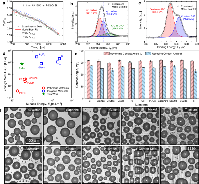
Traditionally, SERS uses nanoparticles made of conductive materials, such as gold, to learn more about a particular molecule. However, of interest in many growing fields that incorporate nanotechnology is the structure and functionalization of a nanoparticle stabilized by some surfactant or capping agent. In this case, SERS can provide valuable information regarding the stability and surface structure of the nanoparticle. Another use of nanoparticles in SERS is to provide information about a ligand’s structure and the nature of ligand binding. In many applications it is important to know whether a molecule is bound to the surface of the nanoparticle or simply electrostatically interacting with it.
Deng, X., Mammen, L., Butt, H. J. & Vollmer, D. Candle soot as a template for a transparent robust superamphiphobic coating. Science 335, 67–70 (2012).
Beam expanders are optical devices which increases the diameter of the input beam to produce a larger output. Used with collimated light, they have important ...
Bejan, A. Fundamentals of exergy analysis, entropy generation minimization, and the generation of flow architecture. Int. J. Energy Res. 26, 0–43 (2002).
Thermal stability of the F-DLC coating compared with HTMS SAM at 300 °C in a nitrogen (N2) and b air environments as measured by the change in apparent advancing contact angles (ACA) and receding contact angles (RCA) with DI water droplets. Contact angle hysteresis (CAH) represents the arithmetic difference between ACA and RCA. Legends are same for (a) and (b). To characterize the effects of abrasion, c the DI water droplet apparent advancing contact angle (blue solid curve) as well as the contact angle hysteresis (blue dashed curve) is plotted as a function of abrasion cycle. The apparent advancing contact angle on F-DLC reduced to ~81° after 5000 abrasion cycles due to d increased surface roughness and e reduced thickness of the top f-DLC layer after abrasion. After 5000 abrasion cycles, the thickness of the F-DLC coating reduces from ~1.65 µm to ~1.61 µm, resulting in exposure to lower fluorine content regions and reduced hydrophobicity. f Dropwise condensation modelling reveals that the droplet Bond number (Bo) is ~1.14 after 5000 abrasion cycles, less than the critical Bond number (Bocrit = 1.4) for dropwise-to filmwise transition. g During high temperature exposure in 300 °C conditions (air), the HTMS surface transitions to filmwise condensation, while the F-DLC coating maintains dropwise condensation. For (a–c), the error bars indicate the standard deviation, which was determined based on three independent measurements conducted for each data point.
The surface energy (\({E}_{{{{{{\rm{s}}}}}}}\)) of the F-DLC coating was measured by probing the advancing contact angle of deionized (DI) water and diiodomethane (Dii) on the F-DLC surface, which yielded \({E}_{s}\) = 24 ± 1 mJ m−2. Details of the surface energy measurement can be found in the “Methods” section19. Although the surface energy is 20% higher when compared to Teflon-like materials having surface energy of ~20 mJ m−2, the F-DLC coating maintains a ~20× higher Young’s modulus. Figure 2d shows the surface energy and Young’s modulus of many commonly used engineering materials, demonstrating that F-DLC combines the merits of both low surface energy and high mechanical modulus.
This result would suggest that Raman spectroscopy is potentially unsuccessful in correctly providing the information about the number of substituents on the SWNTs. Subsequent imaging of the functionalized SWNTs by STM showed that the distribution of the functional groups was the difference between the thiol and thiphene functionalized SWNTs (Figure \(\PageIndex{22}\)). Thus, relative ratio of the D- and G-bands is a measure of concentration and distribution of functional groups on SWNTs.
Abrasion resistance and stability at elevated temperatures is required for a broader array of hydrophobic coating applications. The thermal stability of the F-DLC coating was tested by heating samples in a furnace (Lindberg 2″ Tube Furnace) with a flow of inert gas for various times and temperatures. A continuous flow of N2 gas (~ 3 LPM) in the tube furnace was used. After heating for a prescribed time and allowing the sample to cool back down to room temperature, the apparent advancing (\({\theta }_{{{{{{\rm{a}}}}}}}\)) and receding (\({\theta }_{{{{{{\rm{r}}}}}}}\)) contact angles of DI water droplets were measured using a microgoniometer (MCA−3, Kyowa Interface Science). The heating temperature ranged from 100 °C to 600 °C and at each temperature, five identical F-DLC coated samples were placed in the furnace. After 1 h, the first sample was taken out, followed by the rest of the samples taken out sequentially at 2, 4, 8, and 16 h. The change in apparent contact angle represents an indication of coating integrity due to the intrinsic hydrophilicity of the substrate (metal or native oxide) beneath the F-DLC coating.
The rational design of the multilayer F-DLC coating (Supplementary Fig. 2ii) was guided by our physics-based understanding of condensation-induced blistering. The quantitative parameter that describes blistering, \(\varOmega\), demonstrates that delamination of a hydrophobic coating will occur if \(\varOmega \, > \, 1\)9. Specifically, the blistering parameter \(\varOmega\) is governed by the pinhole size, \({R}_{{{{{{\rm{d}}}}}}}\), the base radius of the pinhole-adjunct delaminated region, \({R}_{b0}\), the liquid-vapor surface tension of the working fluid (water) \(\gamma\), as well as the coating intrinsic properties including its wet adhesion \(G\), Young’s modulus \(E\) and coating thickness \(h\):
Raman spectroscopy of an ensemble of many SWNTs having different chiral vectors is sensitive to the subset of tubes where the condition of allowed transition is fulfilled. A ‘Kataura-Plot’ gives the allowed electronic transition energies of individual SWNTs as a function of diameter d, hence information on which tubes are resonant for a given excitation wavelength can be inferred. Since electronic transition energies vary roughly as 1/d, the question whether a given laser energy probes predominantly semiconducting or metallic tubes depends on the mean diameter and diameter distribution in the SWNT ensemble. However, the transition energies that apply to an isolated SWNT do not necessarily hold for an ensemble of interacting SWNTs owing to the mutual van der Waals interactions.
The ever-rising interest in nanotechnology involves the synthesis and application of materials with a very high surface area to volume ratio. This places increasing importance on understanding the chemistry occurring at a surface, particularly the surface of a nanoparticle. Slight modifications of the nanoparticle or its surrounding environment can greatly affect many properties including the solubility, biological toxicity, and reactivity of the nanomaterial. Noble metal nanomaterials are of particular interest due to their unique optical properties and biological inertness.
To induce water droplet condensation in the atmospheric laboratory environment having air temperature \({T}_{{{{{{\rm{a}}}}}}}\) = 25 ± 1 °C and a relative humidity RH = 50 ± 5% (RO120, Roscid Technologies), we placed the samples horizontally on a cold stage (Linkam T95-PE) and reduced the stage temperature to \({T}_{{{{{{\rm{c}}}}}}}\) = 2.0 ± 0.1 °C to enable observation of water vapor condensation on the substrates using a top-view optical microscopy (Nikon Eclipse LV100) coupled to a monochrome camera (Nikon DS-Qi2)46.
Figure 5c demonstrates that after 5000 abrasion cycles, \({\theta }_{{{{{{\rm{a}}}}}}}\) on the tested F-DLC surface decreased gradually from ~97.5° (fresh F-DLC surface) to ~81.0°. The contact angle hysteresis (Δθ = θa − θr) of the tested surface increased from ~8.0° to ~37.0°. The wettability changes due to the combined effects of increment of local surface energy from partial removal of the top fluorinated layer (f-DLC), and formation of local microscale surface roughness (Fig. 5d). The EDS line scan (Supplementary Fig. 13) of the F-DLC cross section shows the concentration of fluorine in the top f-DLC layer decreases from top to bottom, resulting in a surface energy gradient along the thickness of the f-DLC layer. Cross-sectional SEM analysis shows that after 5000 abrasion cycles, the total coating thickness reduces from ~1.65 µm to ~1.61 µm, only a removal of ~40 nm of the top f-DLC layer, exposing the surface to the lower fluorine content depth, and reducing hydrophobicity. Here we observe that <10% the material was removed after 5000 abrasion cycles, mainly due to the wear resistance originating from the coefficient of friction (COF) DLC material30. The observed abrasion resistance of our F-DLC coating is even better than H-terminated DLC because the two fluorine terminated DLC surfaces sliding against each other would exert higher repulsive forces compared to two H-terminated surfaces. Thus, the mutual interaction of two F-DLC surfaces results in a lower COF31.
a Schematic and b photograph of the facility used to conduct long-term condensation experiments. c Image of the cold plate and sample assembly placed inside of the vacuum chamber for experiments. Throughout the experiment, the surface temperature of the samples was maintained by supplying coolant at 10 °C to the cold plate from a dedicated chiller. Steam is generated inside a separate degassing chamber connected to the bottom of the chamber. d Time-lapse images of steam dropwise condensation on the vertically oriented surfaces consisting of F-DLC coated: (top row) polished Cu, (middle row) polished Al, and (bottom row) polished Si wafer. All results showed hydrophobicity of the F-DLC coating irrespective of substrate for a period lasting more than 3 years at the time of writing this manuscript (March 2022).
The tangential modes are useful in distinguishing semiconducting from metallic SWNTs. The difference is evident in the G- feature (Figure \(\PageIndex{13}\) and \(\PageIndex{14}\)) which broadens and becomes asymmetric for metallic SWNTs in comparison with the Lorentzian lineshape for semiconducting tubes, and this broadening is related to the presence of free electrons in nanotubes with metallic character. This broadened G-feature is usually fit using a Breit-Wigner-Fano (BWF) line that accounts for the coupling of a discrete phonon with a continuum related to conduction electrons. This BWF line is observed in many graphite-like materials with metallic character, such as n-doped graphite intercalation compounds (GIC), n-doped fullerenes, as well as metallic SWNTs. The intensity of this G- mode depends on the size and number of metallic SWNTs in a bundle (Figure \(\PageIndex{15}\)).
Tripathy, A. et al. Ultrathin durable organic hydrophobic coatings enhancing dropwise condensation heat transfer. Langmuir 38, 11296–11303 (2022).
These features are very useful for characterizing nanotube diameters through the relation ωRBM = A/d + B, where A and B are constants and their variations are often attributed to environmental effects, i.e., whether the SWNTs are present as individual tubes wrapped in a surfactant, isolated on a substrate surface, or in the form of bundles. However, for typical SWNT bundles in the diameter range, d = 1.5 ± 0.2 nm, A = 234 cm-1 nm and B = 10 cm-1(where B is an upshift coming from tube-tube interactions). For isolated SWNTs on an oxidized Si substrate, A= 248 cm-1 nm and B = 0. As can be seen from Figure \(\PageIndex{10}\), the relation ωRBM = A/d + B holds true for the usual diameter range i.e., when d lies between 1 and 2 nm. However, for d less than 1 nm, nanotube lattice distortions lead to chirality dependence of ωRBM and for large diameters tubes when, d is more than 2 nm the intensity of RBM feature is weak and is hardly observable.
Ma, J. et al. A lipid-inspired highly adhesive interface for durable superhydrophobicity in wet environments and stable jumping droplet condensation. ACS Nano 16, 4251–4262 (2022).
Although the F-DLC surface can be characterized as hydrophilic (θa < 90°) after 50 abrasion cycles, dropwise condensation and exceptional droplet mobility is maintained due to the maintenance of low contact angle hysteresis20. In fact, the F-DLC surface is predicted to maintain dropwise condensation even after 5000 abrasion cycles due to the maintenance of low droplet Bond number (\({{{{{\rm{Bo}}}}}} \, < \) 1.4). Calculations of \({{{{{\rm{Bo}}}}}}\) for each tested surface based on the abraded surface contact angle measurements reveal a maximum \({{{{{\rm{Bo}}}}}}\) ~ 1.14 after 5000 abrasion cycles. Since \({{{{{\rm{Bo}}}}}} < {{{{{{\rm{Bo}}}}}}}_{{{{{{\rm{crit}}}}}}}\), dropwise condensation occurs on the abraded samples. Continued abrasion experiments up to 10000 cycles showed that our F-DLC coating eventually transitions to droplet pinning and filmwise condensation behavior with Bo ~ 1.9 (Fig. 5f).
Hoque, M.J., Li, L., Ma, J. et al. Ultra-resilient multi-layer fluorinated diamond like carbon hydrophobic surfaces. Nat Commun 14, 4902 (2023). https://doi.org/10.1038/s41467-023-40229-6
202375 — What is FOV? FOV – or field of view – is a term used to indicate just how much of the environment can be seen through a camera at any given time ...
Raman spectroscopy sounds very much like infrared (IR) spectroscopy; however, IR examines the wavenumber at which a functional group has a vibrational mode, while Raman observes the shift in vibration from an incident source. The Raman frequency shift is identical to the IR peak frequency for a given molecule or functional group. As mentioned above, this shift is independent of the excitation wavelength, giving versatility to the design and applicability of Raman instruments.
Donnet C, Erdemir A. Tribology of Diamond-like Carbon Films: Fundamentals and Applications (Springer Science & Business Media, 2007).
Champlin, P. A. Techno-Economic Evaluation of Cross-cutting Technologies for Cost Reduction in Nuclear Power Plants (Department of Nuclear Science and Engineering. Massachusetts Institute of Technology, 2018).
Over the last two decades, the share of global electricity generation provided by solar photovoltaic (PV) and wind energy installations has risen from 0.2% to 10.1%1. However, as much as 70% of global electrical power generation is generated using traditional steam power cycles, which use either a fossil fuel or nuclear fission as the energy source. Therefore, increasing the overall efficiency of steam power plants has a disproportional impact on sustainability, global energy production, and the carbon footprint of developing and developed nations. Among the several strategies to increase power plant efficiency and sustainability, such as deploying supercritical steam cycles2 and optimizing power station infrastructure3, maximizing the steam condenser heat transfer represents the simplest, well known, and promising path to consider. Doing so has been shown to result in a potential 2% net increase in power plant energy efficiency3. If realized today, this efficiency improvement would increase global annual electricity generation by approximately 1000 TWh1, equivalent to matching 83% of the total electricity produced by all global PV installations with no additional increase in carbon emissions.
A large D-peak compared with the G-peak usually means a bad resonance condition, which indicates the presence of amorphous carbon.
1/16" - 3/8" Short Arm Hex Key-Allen Wrench Sets / Alloy Steel / Black Oxide.
Grischke, M., Bewilogua, K., Trojan, K. & Dimigen, H. Application-oriented modifications of deposition processes for diamond-like-carbon-based coatings. Surf. Coat. Technol. 74-75, 739–745 (1995).
a Schematic of the chamber (not to scale) used for the condensation heat transfer experiments. Full details of the chamber and its operation can be found in Supplementary Notes 4a and 4b54,55. The Cu tube sample having outer diameter DOD = 9.53 mm, inner diameter DID = 8.0 mm, and length L = 134.6 mm was cooled via chilled water flowing inside of the tube at 8 ± 0.2 L min−1. b Optical images during condensation showing (top) dropwise condensation on the F-DLC coated smooth Cu tube, and (bottom) filmwise condensation on the smooth uncoated hydrophilic Cu tube. The chamber vapor pressure Pv = 2.67 ± 0.15 kPa was identical for both tests. c Experimentally measured and theoretically computed steady-state condensation heat transfer coefficient (hc) as a function of saturated steam vapor pressure (Pv) on the F-DLC coated Cu (dropwise) and bare Cu (filmwise) tubes. Error bars were computed using the propagation of error (see Supplementary Note 4c). The theoretical prediction for dropwise condensation (blue dotted line) was obtained using the classical droplet growth and distribution model (see Supplementary Note 4d). The theoretical prediction for filmwise condensation (red dotted line) was obtained using the Nusselt filmwise condensation model for a single horizontally oriented tube (see Supplementary Note 4e). For details about the experimental facility, test protocols, and uncertainty propagation, refer to Supplementary Notes 4a, 4b, and 4c.
Khalil, K. et al. Grafted nanofilms promote dropwise condensation of low-surface-tension fluids for high-performance heat exchangers. Joule 3, 1377–1388 (2019).
Ma, J. C., Sett, S., Cha, H., Yan, X. & Miljkovic, N. Recent developments, challenges, and pathways to stable dropwise condensation: a perspective. Appl. Phys. Lett. 116, 260501 (2020).
International Institute for Carbon Neutral Energy Research (WPI-I2CNER), Kyushu University, 744 Motooka, Nishi-ku, Fukuoka, 819-0395, Japan
Figure \(\PageIndex{8}\) shows a typical Raman spectrum from 100 to 3000 cm-1 taken of SWNTs produced by catalytic decomposition of carbon monoxide (HiPco-process). The two dominant Raman features are the radial breathing mode (RBM) at low frequencies and tangential (G-band) multifeature at higher frequencies. Other weak features, such as the disorder induced D-band and the G’ band (an overtone mode) are also shown.
May 20, 2020 — The strongest magnifying glasses for those with visual impairments are Video Magnifiers, also known as Electronic Magnifiers, ...
The magnifying power of a magnifying glass is 10″ (25 cm) divided by its focal length. For example, if you have a lens with a focal length of 4″ (10 cm) it will ...
Khodakarami, S., Zhao, H. Y., Rabbi, K. F. & Miljkovic, N. Scalable corrosion-resistant coatings for thermal applications. ACS Appl. Mater. Interfaces 13, 4519–4534 (2021).


 Ms.Cici
 8618319014500