
Anti Reflective Coating: usage for solar panels - antireflective coating
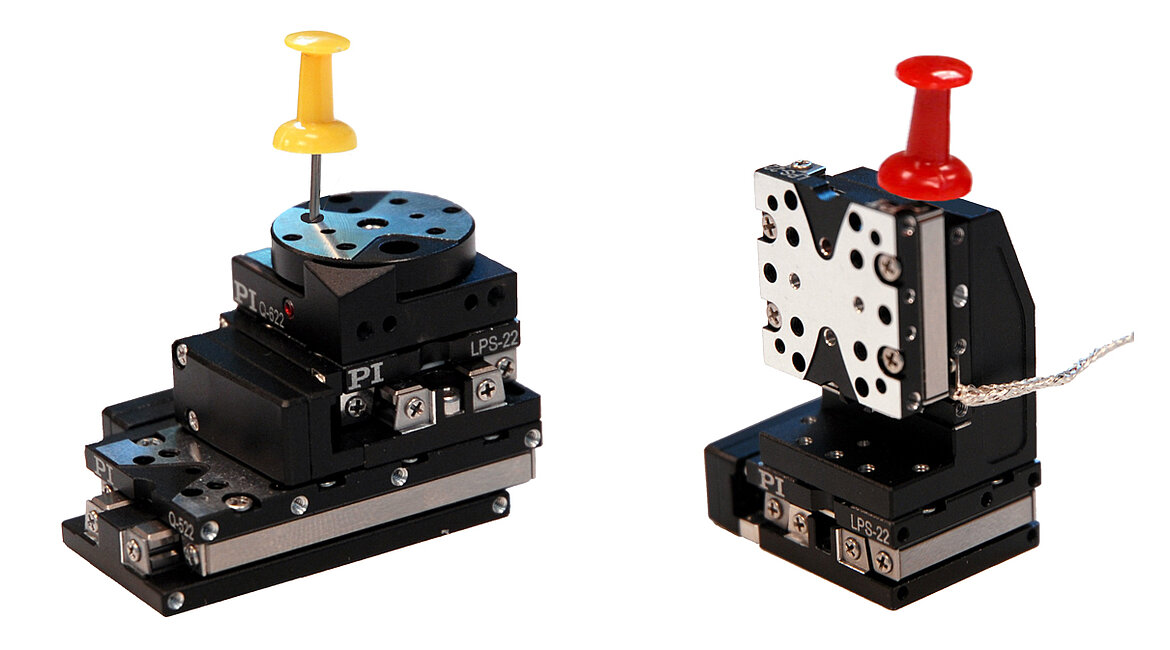
The Q-521 is the smallest linear stage currently available from PI. Based on the stick-slip motor principle, it boasts dimensions as small as 21×30×10mm. Open and closed-loop versions are available. Two linear encoder options for 1 and 4 namometer resolution are offered, both integrated in the stage body, for minimized dimension.
The motors offer multiple operating modes including a high-dynamics, short-range dither mode with 100’s of Hertz bandwidth and picometer resolution, and several long distance modes optimized for highest force, highest speed, and constant velocity.
When the beam divergence angle was measured for the F220FC-A collimator, a 460HP fiber was used with 543 nm light. The result was a divergence angle of 0.018°.
The A-141 miniature Air Bearing Linear Stage is equipped with a 3-phase motor, fully preloaded air bearings, and an integral high-resolution optical linear encoder. A locking design provides the ultimate in position stability. This stage offers ultra-precision in a very compact package.
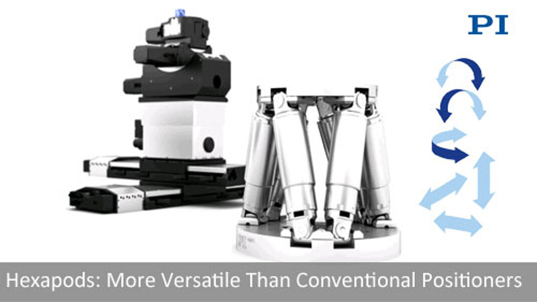
A hexapod is based on a 6-axis (XYZ, Pitch, Roll, Yaw) actuator system arranged between a top and bottom platform. Hexapods are also referred to as Gough-Stewart platforms and offer many advantages over serial kinematics stages, such as lower inertia, improved dynamics, smaller package size, and higher stiffness. In addition, hexapods are more flexible than conventional 6 axis positioners.
where λ is the wavelength of light being used, MFD is the mode field diameter, and f is the focal length of the collimator. (Note: MFD and f must have the same units in this equation).
The M-122 is a compact, high precision linear stage with integrated linear encoder, providing 100 nanometers resolution. It is a bit larger than the M-112, 25mm stage (with motor/gearhead combination), but provides higher speed and precision. Cross roller bearings with anti creep cage assist replace the linear ball bearings in the M-11x stage series.
The L-306 precision vertical stage can be combined with the L-406 linear stage to form compact XZ or XYZ positioning systems.
Collimatorgun
Two collimators, inserted into a fiber optic setup, provide free-space access to the beam. The first collimator accepts the highly diverging light from the first fiber and outputs a free-space beam, which propagates with an approximately constant diameter to the second collimator. The second collimator accepts the free-space beam and couples that light into the second fiber. Some collimation packages, including the pair used in this demonstration, are designed for use with optical fibers and mate directly to fiber connectors.
Fiber collimators are often used to introduce light into an optical setup from a fiber coupled source. Thorlabs offers a variety of fiber collimator packages, some only provide a smooth barrel (like the triplet collimators) and others have a metric thread at the end of the barrel (like the asphere collimators).
The U-521 is the smallest member of the ultrasonic miniature stage family. It is designed for fast, quiet motion and positioning applications with high resolution and excellent step and settle behavior. Equipped with direct position feedback, two versions are offered; a lower-cost 0.4 micron linear encoder and 0.1 micron version for higher precision applications.
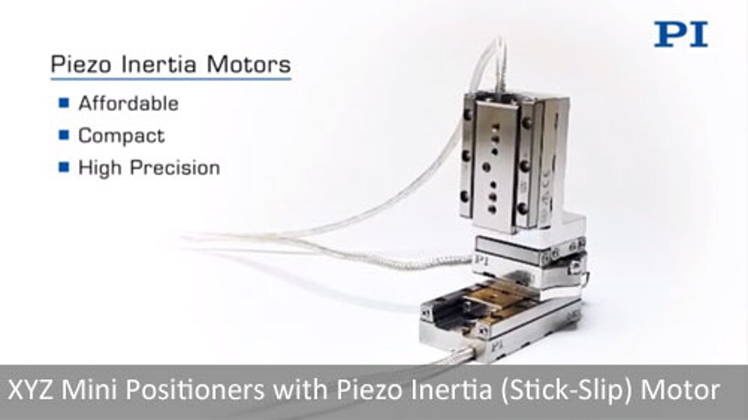
Stick-slip piezo motors (inertia motors) permit the design of the smallest class of precision motorized positioners. The direct drive motors are only a few millimeters in size, there are no gears, or other conventional power transmission components involved that add size, complexity, play or backlash.
These fiber collimation packages are pre-aligned to collimate light from an FC/APC-terminated fiber with diffraction-limited performance. Because these fiber collimators have no movable parts, they are compact and easy to integrate into an existing setup. Due to chromatic aberration, the effective focal length (EFL) of the aspheric lens is wavelength dependent. The design wavelength indicates the wavelength of ideal beam divergence (see the Divergence Plots and Calculations tabs for more information). Collimation packages at select design wavelengths are available with different collimated beam diameters. Select a wavelength from the quick links table to the right for details.
Electromagnetic linear motor-driven stages are used in high-speed positioning, scanning, and automation applications. They have lower holding forces compared to classical motor /screw driven stages, but no wear in the drive train, and are ideal for fast, high-duty cycle motion and positioning applications. .
These compact motorized rotation stages provide unlimited rotation ranges. The use of a worm gear reduction mechanism converts high speed input from the servo or stepper motor into high resolution motion at the turn table. Open loop stepper/gear motor and closed-loop servo gear motor versions with motor shaft mounted encoders are available.
where f is the focal length of the collimator, λ is the wavelength of light used, and MFD is the mode field diameter. (Note: MFD and f must have the same units in this equation).
Piezo flexure stages are used when extremely smooth motion, fast response, high force or continuous scanning is required, with travel ranges typically below 1 millimeter. PI flexure stages are driven with PI’s exclusive PICMA piezo elements that have been life tested for 100 billion cycles and were selected by NASA /JPL for the Mars mission due to their extremely high performance and reliability.
If you would like more information about tips, tricks, and other methods we often use in the lab, we recommend our other Video Insights. In addition, our webinars provide practical and theoretical introductions to our different products.
Piezo flexure-guided positioning stages provide several advantages over classical motorized positioning systems with mechanical bearings. They are completely free of backlash and friction and can position and settle in milliseconds or even microseconds. Driven by a piezo ceramic (with optional flexure motion amplifier), the response time is based on the sound propagation in the ceramics.
In addition to hexapods, PI offers a second class of planar 6-axis parallel manipulators. These piezo motor driven units are even smaller and fit inside the palm of a hand.
The smallest motorized stages offered are the finger-tip-sized, inertia motor-driven Q-Motion positioners. For the highest performance, the flexure guided PIhera series is recommended.
CollimatorX ray
The maximum waist distance, which is the furthest distance from the lens the waist can be located in order to maintain collimation, may be approximated by
Wear and Friction Free Bearings, No Particle Generation Flexures and air bearings provide friction free and wear free precision guidance.
Simulations of the theoretical divergence when using one of our standard collimators at wavelengths other than the design wavelength are shown in the graphs below. For example, if you need to collimate 700 nm light from a fiber into a ~1.5 mm diameter beam, the F240APC-780 collimator (represented by the '-780' line in the F240 graph below) can be used but will provide a higher divergence than at its design wavelength of 780 nm. Individual theoretical divergence plots and raw data are also available below for each collimator. Please contact Tech Support to request a collimator aligned at a custom wavelength.
Collimatorin radiology
The V-52x series of voice-coil-driven linear stages come in 3 sizes and provide high-dynamics over travel ranges of 5mm, 10mm, and 20mm. Applications include optics scanning, fiber alignment, biotechnology, and laser technology. These compact linear scanning stages achieve significantly higher dynamics and speed than conventional screw-type positioners with stepper and servo motors; scanning frequencies of several 10Hz with velocities up to 250mm/sec can be achieved with the recommended C-413 compact controller. The design uses no moving cables and the frictionless voice-coil drive is not subject to wear & tear and generates no particles.
The V-408 features high load capacity precision crossed roller elements with anti-creep cage assist, preventing roller creep, and a zero-wear, non-contact linear motor – ideal prerequisites for long lifetime in high duty cycle industrial applications. The high-force linear motor achieves velocities up to 0.7m/sec. An integrated optical linear encoder provides 10 nanometers resolution. The stage achieves 20nm minimum incremental motion and excellent geometric performance with 4µm straightness and flatness.
Voice Coil Actuators use a one-phase electromagnetic linear motor similar to the driver of a loud-speaker. They provide high velocity with zero wear and motion ranges typically up to 1 inch.
Ultrasonic motors are self-clamping at rest, provide excellent long-term stability, there is no servo dither, or energy consumption once a position has been reached. While high velocities can be achieved with ultrasonic motors, when continuous scanning is required, magnetic linear motors and voice-coil drives, such as in the V-522 miniature stage, are recommended. Ultrasonic drives permit the design of very compact positioners; the motor design is intrinsically non-magnetic and vacuum compatible.
Although this collimator is factory aligned for a specific wavelength, it has low divergence angles over a broad range of wavelengths. Therefore, it may be used at other wavelengths within the AR coating range. Please refer to the theoretical divergence plot for this collimator to determine if it is appropriate for your application.
Although this collimator is factory aligned for a specific wavelength, it has a low divergence angle over a broad range of wavelengths. Therefore, it may be used at other wavelengths within the AR coating range. Please refer to the theoretical divergence plot for this collimator to determine if it is appropriate for your application.
Collimatorin spectrometer
Micropositioners with stepper motors and linear motors and lead-screw or ball-screw drives are often employed when relatively high forces are required, speed requirements are moderate, and controls need to be simple.
Piezo inertia motors can be operated in open loop, but for high accuracy and repeatability, a position encoder is integrated in the stage. Vacuum compatible and non-magnetic versions are also offered. The PIShift piezo inertia drive is very quiet, due to its high operating frequency of 20 kHz.
These fiber collimators are intended for use with single mode fiber patch cables. For improved performance, we recommend using these collimators with our AR-coated single mode fiber optic patch cables. These cables feature an antireflective coating on one fiber end for increased transmission and improved return loss at the fiber-to-free-space interface. Please note performance specifications are guaranteed only when used with single mode fiber.
However, the use of these adapters results in a stack up of threaded interfaces (threaded fiber connector, threaded collimator, and threaded adapter). As a result, it is possible that unscrewing the fiber connector could inadvertently loosen another thread interface and create an unknown source of instability in the setup.
Applications for this positioner are in precision automation, metrology, photonics alignment, optics positioning, and scanning. The non-contact design avoids particle generation and makes these PIglide air bearing stages ideal for cleanroom applications.
When the F220FC-532 collimator (f = 10.9 mm) is used with the P1-460B-FC-1 patch cable (MFD ≈ 4.0 µm; calculated approximate value) and 532 nm light, then the maximum waist distance is approximately
The continuous need for miniaturization in industry and research requires smaller precision motorized rotation stages for many alignment applications in optics, photonics and medical design.
Mid-IR CollimatorsFor our collimators with an alignment wavelength of 3.45 µm and 4.55 µm, we recommend using our angle-polished fluoride fiber patch cables; these collimators include a tightly toleranced ceramic sleeve to protect the fluoride fiber tip during insertion and improve pointing stability. Although these collimators are factory aligned for a specific wavelength, they have low divergence angles over a broad range of wavelengths. Therefore, they may be used at other wavelengths within the AR coating range. Please refer to the theoretical divergence plot for each collimator to determine if it is appropriate for your application.
Inertia piezo motors make use of the difference in the static and dynamic friction coefficients between two surfaces; their controllers provide a quasi sawtooth output voltage, with a slow expansion phase and a fast contraction phase. In the expansion phase, the piezo actuator moves the slider; in the contraction phase, its inertia prevents the slider from following the quick motion of the actuator, and it remains at its position.
The Q-545 mini positioning stage is driven by a higher force stick slip motor, based on a slightly different design compared to the Q-521 stage. A linear encoder is integrated for nanometer-scale precision. The piezo inertia drive runs at inaudible frequencies and is self-clamping at rest with position holding forces around 2 lbs.
PI offers micropositioners with lead screws (typically higher resolution and holding forces) and ball screws (higher speed, lower friction). Both are available with closed-loop servo motors and stepper motors.
The A-142 is our smallest motorized Air Bearing Linear Stage. It is driven by a voice coil motor and equipped with a high-resolution optical linear encoder. A brake and air springs can be added for vertical applications.
Adapters for the external thread are available (AD1109F) that allow the user to thread the fiber collimator into a mount.
AlternativesWe also offer a line of adjustable collimation packages called FiberPorts that are well suited for a wide range of wavelengths. These are ideal solutions for adjustable, compact fiber couplers. For other collimation and coupling options, please see our Collimator Guide tab or contact Tech Support.
For both packages, Thorlabs typically suggests the use of an adapter with a nylon tipped set screw that holds the barrel against a two line contact.
Collimatorsight
These highly engineered motorized micropositioners are available in different sizes and motion ranges. Most models can easily be combined to form X-Y micropositioners (see graphic below). PI offers open and closed-loop micropositioning stages with precision ranges from 1 micron to sub-nanometer resolution. The selection includes linear positioners and rotary tables, single-axis and multi-axis stage assemblies, for ambient and vacuum environments, custom designs and non-magnetic motorized stages are also available.
collimatoris used for?
where MFD is the mode field diameter and f is the focal length of the collimator. (Note: MFD and f must have the same units in this equation).
Collimator-AI
PiezoWalk is a more powerful and complex drive than stick-slip and ultrasonic motors. PiezoWalk motors combine long travel with high stiffness and force, providing virtually unlimited travel ranges. PI’s NEXACT® motor technology integrates these advantages into a small package. Piezo-class resolution, millisecond responsiveness with low operating voltages, and a self-clamping design are other features.
When the F220FC-A collimator (f ≈ 11.0 mm; not exact since the design wavelength is 543 nm) is used to collimate 515 nm light emerging from a 460HP fiber (MFD = 3.5 µm), the divergence angle is approximately given by
Custom Stages for OEMs: Since one design can NOT fit all applications, please contact a PI engineer and they will work with you on the best standard or custom solution for your motion application.
To mount these fiber collimation packages, we recommend using our collimator mounting adapters, including our kinematic collimator mounting adapters that provide pitch and yaw adjustment. In addition to Ø1/2" and Ø1" unthreaded versions, options are available with external SM05 (0.535"-40), RMS (0.800"-36), or SM1 (1.035"-40) threading. The collimation packages with external M12 x 0.5 threading can be mounted directly into our cage plate CP1M12(/M) to be integrated into our 30 mm cage systems.
Motorized miniature linear stages and miniature rotary stages (often referred to as micropositioners) are offered in a variety of designs, each optimized for a range of specific applications. When the highest dynamic performance and travel ranges in the centimeter range is required, along with continuous scanning operation, motorized miniature stages with voice-coil drives are often a good starting point. Longer travel ranges, higher forces, and even higher velocities are achievable with closed-loop 3-phase linear motor stages. Ultrasonic direct-drive piezo motor linear stages and rotary stages also provide very high speed and acceleration, and their inherently self-clamping design is an advantage in applications that require dynamics and high stability over longer periods with no heat generation. More traditional approaches are based on lead-screw and ball-screw drives with stepper motors or closed-loop servo motors. When nanometer and sub-nanometer performance is paramount, piezo flexure stages are hard to beat. Independent of the use case, compact, high precision positioning stages are crucial for the miniaturization process in cutting-edge research and industrial applications, such as test & measurement, optical and opto-mechanical alignment, photonics automation and component assembly. PI provides the largest portfolio of motorized miniature linear stages and rotary tables, including high-speed electromagnetic linear motors, economical stepper motor units, and ultra-compact piezo motor positioners, all available from single axis to multi-axis systems.
These ultrasonic motor driven rotation stages provide high velocity to 720°/second and compact dimensions. They are equipped with optical, direct metrology encoders, and due to the self-clamping motor design, boast excellent position stability. The U-628 is the largest example featuring a table diameter of just under 2”. With Ø30mm and Ø20mm, respectively, the U-624 and U-622 are even more compact versions of the U-628 rotary stage.
Collimatorlens
Ideally, 100% of the light emitted by the first fiber would be coupled into the second fiber, but some light will always be lost due to reflections, scattering, absorption, and misalignment. Misalignment, typically the largest source of loss, can be minimized using the alignment and stabilization techniques described in this video.
The beam diameter as a function of propagation distance was simulated for each of our collimators at the design wavelength, assuming input from the design fiber and a Gaussian intensity profile. The design wavelength and fiber are specified in the caption for each graph.
The new L-505 is available in many configurations with linear encoders down to 5 nm resolution. It provides a very good balance of cost and precision.
Folded Drive Trains: M-11x and M-12x Stages are especially compact through the use of a folded drive train. The M-110, M-111 and M-112 series is PI’s smallest positioning stage family with “classical” motor drives. It is offered with lead screws (higher resolution and holding force) and ball screws (higher speed, lower friction). The DC-servo motor versions come with motor mounted encoders (calculated resolution as low as 7 nanometers); the stepper motor driven versions are run open loop. Guidance is with linear ball bearings. X, XY, and XYZ combinations are available.
In this demonstration, the first fiber is single mode. The optical power incident on the second collimator, as well as the power output by the second fiber, are measured. When the second fiber is multimode with a 50 µm diameter core, alignment resulted in 91% of the power incident on the second collimator being measured at the fiber output. This value was 86% when the second fiber is single mode. Some differences in collimator designs, and their effects on the characteristics of the collimated beams, are also discussed.
For this reason, Thorlabs suggests epoxying the threaded fiber collimators into the threaded mounts if that mounting mechanism is preferred.
The aspheric lens is factory aligned for collimation at the design wavelength when connected to its specified single mode fiber patch cable. In addition, the aspheric lens has an AR coating on both sides that minimizes surface reflections (see the AR Coating Plots tab). For some applications they may also be used at other wavelengths within the AR coating range; please refer to the theoretical divergence plot for each collimator to determine if it is appropriate for your application. The operating temperature range for these collimators is -40 °C to 93 °C. Please note that these collimation packages are not vacuum compatible. Collimation packages with custom alignment wavelengths, operating temperature ranges, or vacuum compatibility are available by contacting Tech Support.
Compliance with Applicable Laws; Export Control Laws User access to this website is governed by all applicable federal, state, and local laws. All information available on this website is subject to U.S. export control laws and may also be subject to the laws of the country where you reside.
The full-angle beam divergence listed in the specifications tables is the theoretically-calculated value associated with the fiber collimator. This divergence angle is easy to approximate theoretically using the formula below as long as the light emerging from the fiber has a Gaussian intensity profile. Consequently, the formula works well for single mode fibers, but it will underestimate the divergence angle for multimode (MM) fibers since the light emerging from a multimode fiber has a non-Gaussian intensity profile.
The divergence angle can be estimated using the formula shown to the right, given that the light emerging from the fiber has a Gaussian intensity profile. This formula works well for single mode fibers but will underestimate the divergence angle for multimode fibers where the light emerging from the fiber has a non-Gaussian intensity profile.
Ultrasonic motor direct drives are based on the piezo effect. A compact piezoceramic actuator is driven at inaudible frequencies of 100’s of kHz (hence the ultrasonic designation), and with each cycle transfers nanoscopic motion to a linear or rotary ceramic surface bonded to a linear runner or rotary platform. Ultrasonic motors provide very fast start/stop behavior, smooth motion with a very wide dynamic range from microns/second to 100’s of millimeters/second.
When the F240FC-1550 collimator (f = 8.18 mm) is used with the P1-SMF28E-FC-1 patch cable (MFD = 10.4 µm) and 1550 nm light, the output beam diameter is


 Ms.Cici
 8618319014500