
Angle Bracket - Mounting Brackets - right angle brackets
The depth of field is the zone within a photo that appears acceptably sharp and in focus. In every picture, there is a point of focus – the spot where you ...
Retroreflector mirror
By utilizing this focal length calculator tool, you can determine the focal length needed to capture an image of an object at a specified distance. This calculation allows you to ensure that desired field of view will be captured by your optical module.
How do retroreflectors work
Mar 16, 2023 — Acknowledge how the customer feels, and show that you care · Apologize for any negative experience · Put yourself in customers' shoes and make ...
Online Shop ; MagniBar ; MagniBar. LED illuminated bar magnifier. Magnification: 2x (with powerful spot insert) Size: 155mm x 25mm (approx). Product Details ...
RetroReflector Tape
The angular field of view (AFOV), which represents the extent of the observable scene in degrees, can be derived from the field of view (FOV) and working distance (WD).
retro-reflector on moon
Aperture setting. The aperture setting has the largest factor in determining the depth of field of your images. Just remember that f4, 3.5 or 2.8 (or larger) ...
Retroreflective material
We present laboratory measurements of the polarization state of a beam retroreflected through a Thorlabs retroreflector. In a polarization-dependent experiment, it's important to understand how the polarization of the input beam is altered during retroreflection. While input beams normal to the base strike each face of the retroreflector at a roughly 55° angle of incidence [1], the s and p polarization components experience different phase delays and are split differently, depending on the order of surfaces they reflect from. The base of the retroreflector is imagined to be divided into sextants; a beam incident on any one sextant will be retroreflected through the sextant sharing the same vertical angle (see figure to the right). We find that the change in polarization is dependent upon initial polarization of the beam and input sextant.
Visit our optical products pages for a full list of C-Mount lenses, M12/M10/M8/M6 screw mount lenses, optical filters, and optics accessories including custom designed lens mounts, extension tubes and adapters.
[1] J. Liu and R. M. A. Azzam, "Polarization properties of corner-cube retroreflectors: theory and experiment," Applied Optics 36, 1553-1559 (1997).[2] E. R. Peck, "Polarization properties of corner reflectors and cavities," J. Opt. Soc. Am. 52, 253-257 (1962).[3] P. Rabinowitz, S. F. Jacobs, T. Shultz, and G. Gould, "Cube-corner Fabry-Perot interferometer," J. Opt. Soc. Am. 52, 452-453 (1962).[4] P.I Lamekin, "Intrinsic polarization states of corner reflectors," Sov. J. Opt. Tech. 54, 658-661 (1987).[5] M. A. Acharekar, "Derivation of internal incidence angles and coordinate transformations between internal reflections for corner reflectors at normal incidence," Opt. Eng. 23, 669-674 (1984).
retro-reflective panels invisibility
The two figures below summarize the measured results for the retroreflected polarization. The lower left figure shows the output beam by sextant for vertical input polarization; the lower right figure shows the output beam by sextant for horizontal input polarization. In both enlarged figures, A and B denote the major and minor axes respectively for the polarization ellipse. Θ is the angle between the major axis and the horizontal. Arrow heads mark the handedness of the polarization. Both Θ and handedness are reported as seen by an observer looking into the retroreflector. These measured results demonstrate that the polarization state of the retroreflected beam is dependent not only on the initial polarization of the incident beam, but also the sextant of the retroreflector that the beam in incident upon. For details on the experimental setup employed and the results summarized here, please click here.
For our experiment we used the previous-generation HRS015 stabilized HeNe laser. The beam was retroreflected by a Ø1" N-BK7 prism retroreflector and propagated through a polarizer, after which its power was recorded. We measured beam power with the polarizer oriented horizontally, vertically, or at ±45°. Next, we inserted a quarter-wave plate into the beam path before the polarizer with the fast axis of the λ/4 wave plate aligned horizontally. The power of the beam was recorded with the polarizer set at ±45°. From this set of six measurements, the Stokes parameters were calculated, which yielded the parameters for the electric field polarization ellipse.
Ein 50 mm Objektiv hat an einer APS-C Kamera, an einer Vollformat Kamera und an allen anderen Kamerasystemen eine Brennweite von 50mm. Was sich an verschiedenen ...
Retroreflector
Determine the best optical fit for your project based on the required sensor size and image circle, desired operating range and field of view (FOV), and lens type requirements specific to your application.
Apr 6, 2022 — F-stop (aka f-number) is the number that you see on your camera or lens as you adjust the size of your aperture. · Since f-stops are fractions, ...
Kits Eyewear. Canada's #1 Eyewear Store. High-quality eyewear at affordable prices. All KITS glasses and sunglasses are now available starting at $28.
What are retroreflectors used for

The effects of retroreflectors on polarization state have been investigated via various methods: eigenpolarization states [2 - 4], internal incidence angles using transformations between internal reflections [5], and analytic geometry [1]. We present experimental results of polarization state changing through retroreflection and compare it to the theory developed in Ref. [1] though examination of the proper Jones and Rotation matrixes.
Keep in mind that this formula assumes thin lenses and a paraxial approximation, which are valid for many practical situations. However, for complex optical systems or special lenses, additional considerations and corrections may be required for accurate calculations.
Easily calculate displacement or the straight-line distance between two points with our online tool. Simply input the coordinates to obtain accurate results ...
Barrel distortion is one of the most common lens distortions in photography, and it generally happens when you use a wide-angle lens (or the wide portion of a ...
By measuring the object distance (u) and the corresponding image distance (v), you can substitute these values into the lens formula and find the focal length (f). It’s important to know that the focal length of photographic lenses is usually expressed in millimeters (mm).
The focusing power of a lens and its focal length is inversely proportional. A lens with a longer focal length, when compared to a lens with a shorter focal length, will result in a smaller field of view and increased magnification of objects. The field of view can be expressed as a dimension in millimeters or degrees. When the sensor size (H), desired field of view (FOV), and working distance (WD) are known, it is possible to estimate the required focal length (f) of the lens using the following equation.
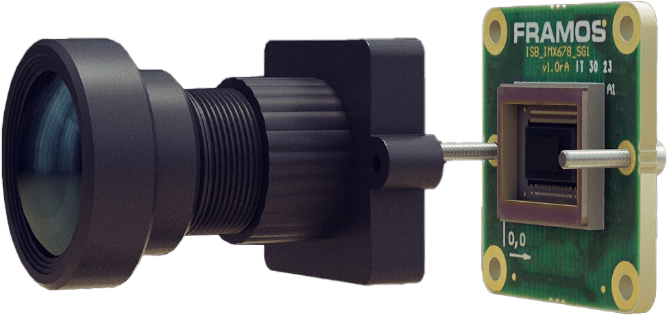
You can save development effort and reduce product costs with an optical module. Optical modules include a high-performance image sensor module paired with an ideally matched lens and lens mount, which provides easy compatibility with your choice of image processing board via FRAMOS’s standardized PixelMate™ interface.
10 Ring Light with Stand and Phone Holder, A USB Ring Light for Desk with Remote Control, Overhead Camera Mount with Adjustable Arm and C-Clamp for ...
It should be noted that as the field of view widens, the resulting image may exhibit more distortion. In certain cases, distortion can be mitigated using dewarping techniques. However, it is advisable to select a lens optimized for the intended field of view to minimize distortion in the original image.


 Ms.Cici
 8618319014500