
Allen Wrench - 5/64 - 5/64 allen wrench
Diffractionresolution
In Gaskill's notation, the sensing area is a 2D comb(x, y) function of the distance between pixels (the pitch), convolved with a 2D rect(x, y) function of the active area of the pixel, bounded by a 2D rect(x, y) function of the overall sensor dimension. The Fourier transform of this is a comb ( ξ , η ) {\displaystyle \operatorname {comb} (\xi ,\eta )} function governed by the distance between pixels, convolved with a sinc ( ξ , η ) {\displaystyle \operatorname {sinc} (\xi ,\eta )} function governed by the number of pixels, and multiplied by the sinc ( ξ , η ) {\displaystyle \operatorname {sinc} (\xi ,\eta )} function corresponding to the active area. That last function serves as an overall envelope to the MTF function; so long as the number of pixels is much greater than one, then the active area size dominates the MTF.
If objects within the scene are in motion relative to the imaging system, the resulting motion blur will result in lower spatial resolution. Short integration times will minimize the blur, but integration times are limited by sensor sensitivity. Furthermore, motion between frames in motion pictures will impact digital movie compression schemes (e.g. MPEG-1, MPEG-2). Finally, there are sampling schemes that require real or apparent motion inside the camera (scanning mirrors, rolling shutters) that may result in incorrect rendering of image motion. Therefore, sensor sensitivity and other time-related factors will have a direct impact on spatial resolution.
Massresolution
Robotic vision can identify objects, measure distances and track motion, enabling robots to perform complex tasks autonomously.
This is the result of our decades of experience with extremely tight tolerances. We even go so far as to design and build our own manufacturing and metrology systems if there is no equipment available on the market that is accurate enough. Our customers value us not only for our technical expertise, but also for the dedicated and customer-focused advice we provide. We listen. We answer questions and make recommendations. It is important to us that our customers have all the information they need so that they can make the right decisions and achieve the best possible results. Contact us. We will be happy to advise you.
B/G/I/K television system signals (usually used with PAL colour encoding) transmit frames less often (50 Hz), but the frame contains more lines and is wider, so bandwidth requirements are similar.
Optical resolution describes the ability of an imaging system to resolve detail, in the object that is being imaged. An imaging system may have many individual components, including one or more lenses, and/or recording and display components. Each of these contributes (given suitable design, and adequate alignment) to the optical resolution of the system; the environment in which the imaging is done often is a further important factor.
The EIA 1956 resolution chart was specifically designed to be used with television systems. The gradually expanding lines near the center are marked with periodic indications of the corresponding spatial frequency. The limiting resolution may be determined by inspection. The most important measure is the limiting horizontal resolution, since the vertical resolution is typically determined by the applicable video standard (I/B/G/K/NTSC/NTSC-J).
An interferogram created between two coherent light sources may be used for at least two resolution-related purposes. The first is to determine the quality of a lens system (see LUPI), and the second is to project a pattern onto a sensor (especially photographic film) to measure resolution.
When using other methods, including the interferogram, sinusoid, and the edge in the ISO 12233 target, it is possible to compute the entire MTF curve. The response to the edge is similar to a step response, and the Fourier Transform of the first difference of the step response yields the MTF.
The above estimates of resolution are specific to the case in which two identical very small samples that radiate incoherently in all directions. Other considerations must be taken into account if the sources radiate at different levels of intensity, are coherent, large, or radiate in non-uniform patterns.
Difference betweenresolutionand resolvingpowerin microscope
by A Van Eeckhout · 2021 · Cited by 9 — The depolarization, which eventually appears in the polarimetric measurement of the optical response of any physical system, arises from the ...
This formula is suitable for confocal microscopy, but is also used in traditional microscopy. In confocal laser-scanned microscopes, the full-width half-maximum (FWHM) of the point spread function is often used to avoid the difficulty of measuring the Airy disc.[1] This, combined with the rastered illumination pattern, results in better resolution, but it is still proportional to the Rayleigh-based formula given above. r = 0.4 λ N A {\displaystyle r={\frac {0.4\lambda }{\mathrm {NA} }}}
The IEEE 208-1995 resolution target is similar to the EIA target. Resolution is measured in horizontal and vertical TV lines.
Short exposures suffer from turbulence less than longer exposures due to the "inner" and "outer" scale turbulence; short is considered to be much less than 10 ms for visible imaging (typically, anything less than 2 ms). Inner scale turbulence arises due to the eddies in the turbulent flow, while outer scale turbulence arises from large air mass flow. These masses typically move slowly, and so are reduced by decreasing the integration period.
We design and manufacture both the mechanics and the coatings of our filters at Schneider-Kreuznach. This enables us to produce customized optical filters that meet your exact requirements and guarantee the highest quality standards.
Does anyone knows why a 50 mp ... Unprocessed 50MP image from the main camera from the Motorola Edge 30 Ultra ... shoots 50 megapixel high resolution mode pictures.
When a condenser is used to illuminate the sample, the shape of the pencil of light emanating from the condenser must also be included.[3] r = 1.22 λ N A obj + N A cond {\displaystyle r={\frac {1.22\lambda }{\mathrm {NA} _{\text{obj}}+\mathrm {NA} _{\text{cond}}}}}
An imaging system running at 24 frames per second is essentially a discrete sampling system that samples a 2D area. The same limitations described by Nyquist apply to this system as to any signal sampling system.
As a family owned company, we are passionate and committed to our customers and their success. You can expect long-term relationships based on trust and shared goals with us.
The interferogram used to measure film resolution can be synthesized on personal computers and used to generate a pattern for measuring optical resolution. See especially Kodak MTF curves.
The transformation to be used is the Fourier transform. M T F s y s ( ξ , η ) = M T F a t m o s p h e r e ( ξ , η ) ⋅ M T F l e n s ( ξ , η ) ⋅ M T F s e n s o r ( ξ , η ) ⋅ M T F t r a n s m i s s i o n ( ξ , η ) ⋅ M T F d i s p l a y ( ξ , η ) {\displaystyle {\begin{aligned}\mathbf {MTF_{sys}(\xi ,\eta )} ={}&\mathbf {MTF_{atmosphere}(\xi ,\eta )\cdot MTF_{lens}(\xi ,\eta )\cdot } \\&\mathbf {MTF_{sensor}(\xi ,\eta )\cdot MTF_{transmission}(\xi ,\eta )\cdot } \\&\mathbf {MTF_{display}(\xi ,\eta )} \end{aligned}}}
Ever since the foundation in 1913 our staff have been perfecting our knowledge and technologies to bring you the best products in optics. Our manufacturing facilities in Bad Kreuznach, Germany, guarantee outstanding quality – Made in Germany. We continuously invest in our state-of-the-art machinery and in the education and training of our staff. Select your perfect filter from our large portfolio of optical filters.
This article explains the difference between orthometirc (geoid) height and ellipsoidal height. The orthometric (geoid) height of a point of the Earth ...
The OTF accounts for aberration, which the limiting frequency expression above does not. The magnitude is known as the Modulation Transfer Function (MTF) and the phase portion is known as the Phase Transfer Function (PTF).
Discover our wide range of high quality lenses, optical filters and accessories in our interactive eBrochure. Find the detailed compilation of all standard products currently available from Schneider-Kreuznach.
r = 1.22 λ 2 n sin θ = 0.61 λ N A {\displaystyle r={\frac {1.22\lambda }{2n\sin {\theta }}}={\frac {0.61\lambda }{\mathrm {NA} }}} where
What is the function of a polarizer filter? A polarizing filter, also called a polarizer, consists of a polarizing film that allows partially polarized light to pass through. This eliminates reflections and increases contrast.
Systems looking through long atmospheric paths may be limited by turbulence. A key measure of the quality of atmospheric turbulence is the seeing diameter, also known as Fried's seeing diameter. A path which is temporally coherent is known as an isoplanatic patch.
To find a theoretical MTF curve for a sensor, it is necessary to know three characteristics of the sensor: the active sensing area, the area comprising the sensing area and the interconnection and support structures ("real estate"), and the total number of those areas (the pixel count). The total pixel count is almost always given. Sometimes the overall sensor dimensions are given, from which the real estate area can be calculated. Whether the real estate area is given or derived, if the active pixel area is not given, it may be derived from the real estate area and the fill factor, where fill factor is the ratio of the active area to the dedicated real estate area. F F = a ⋅ b c ⋅ d {\displaystyle \mathrm {FF} ={\frac {a\cdot b}{c\cdot d}}} where
Resolutionand resolvingpower ofmicroscope
The human brain requires more than just a line pair to understand what the eye is imaging. Johnson's criteria defines the number of line pairs of ocular resolution, or sensor resolution, needed to recognize or identify an item.
The SN2-Mount is designed for polarizers and achieves highest possible aperture, avoiding vignetting in machine vision systems. Its unique locking mechanism fixes the correct orientation, even in typical industrial environment. The filters are glued into the mount to secure them against vibrations when integrated into robots or production lines. Ideal to be used in automated fabrication.
A system limited only by the quality of the optics is said to be diffraction-limited. However, since atmospheric turbulence is normally the limiting factor for visible systems looking through long atmospheric paths, most systems are turbulence-limited. Corrections can be made by using adaptive optics or post-processing techniques.
In imaging systems, the phase component is typically not captured by the sensor. Thus, the important measure with respect to imaging systems is the MTF.
The best visual acuity of the human eye at its optical centre (the fovea) is less than 1 arc minute per line pair, reducing rapidly away from the fovea.
Schneider-Kreuznach offers a variety of mounts for polarizers with common thread sizes to fit on most camera lens systems. The DH-Mount is rotatable to adjust polarization axis in the required orientation. Filters are held by retainer rings.
A multiburst signal is an electronic waveform used to test analog transmission, recording, and display systems. The test pattern consists of several short periods of specific frequencies. The contrast of each may be measured by inspection and recorded, giving a plot of attenuation vs. frequency. The NTSC3.58 multiburst pattern consists of 500 kHz, 1 MHz, 2 MHz, 3 MHz, and 3.58 MHz blocks. 3.58 MHz is important because it is the chrominance frequency for NTSC video.
This is analogous to taking the Fourier transform of a signal sampling function; as in that case, the dominant factor is the sampling period, which is analogous to the size of the picture element (pixel).
Resolution depends on the distance between two distinguishable radiating points. The sections below describe the theoretical estimates of resolution, but the real values may differ. The results below are based on mathematical models of Airy discs, which assumes an adequate level of contrast. In low-contrast systems, the resolution may be much lower than predicted by the theory outlined below. Real optical systems are complex, and practical difficulties often increase the distance between distinguishable point sources.
Shop for anti spy detector and camera finder at Best Buy. Find low everyday prices and buy online for delivery or in-store pick-up.
We demand the highest standards of materials and manufacturing processes to ensure excellent image quality, starting with the production of the optics. Our standards go beyond the production of individual components. We master the entire production process from raw glass to finished filters and are able to process all common types of glass. Our special coating technologies give the optics or lenses the desired optical properties.
May 25, 2024 — All you have to do is provide the resolution of your video and its color depth. If you want to calculate the file size of a video that uses a ...
Now substitute the di and do values into the lens equation 1 / f = 1 / do + 1 / di to solve for the focal length. 1 / f = ...
The other method is to transform each of the components of the system into the spatial frequency domain, and then to multiply the 2-D results. A system response may be determined without reference to an object. Although this method is considerably more difficult to comprehend conceptually, it becomes easier to use computationally, especially when different design iterations or imaged objects are to be tested.
Spatial resolution is typically expressed in line pairs per millimeter (lppmm), lines (of resolution, mostly for analog video), contrast vs. cycles/mm, or MTF (the modulus of OTF). The MTF may be found by taking the two-dimensional Fourier transform of the spatial sampling function. Smaller pixels result in wider MTF curves and thus better detection of higher frequency energy.
All sensors have a characteristic time response. Film is limited at both the short resolution and the long resolution extremes by reciprocity breakdown. These are typically held to be anything longer than 1 second and shorter than 1/10,000 second. Furthermore, film requires a mechanical system to advance it through the exposure mechanism, or a moving optical system to expose it. These limit the speed at which successive frames may be exposed.
Schneider Kreuznach polarizers are designed to fulfill industrial requirements. They are made of dichroic laminated polarizing polymers cemented between 2 slides of protective glass. Additionally we offer polarizing film for larger sizes or customized shapes and flexible solutions. Polarizing Films consist of long chain polymers, which are aligned by a stretching process to produce the polarization effect. The polarizing film is covered on both sides with cellulose triacetate (TAC) for protection and is therefore mechanically stable. Call us to discuss your OEM and custom requirements.
resolving power中文
Quality and reliability are top priorities at Schneider-Kreuznach. Our filters undergo rigorous quality control to ensure maximum reliability. We use only high quality glass from reputable manufacturers to achieve very low manufacturing tolerances. As a result, our filters are of consistently high quality. Their use allows you to accurately reproduce results, as the filters will perform nearly identically even after years of use.
This polarizing film is a replacement part for our AR400 Polarizing Filter in case it gets damaged. It's already cut with drilled holes to perfectly fit the ...
Do you have any questions or comments? Then please contact us. We will get back to you as soon as possible. To help us process your request, please fill out all fields marked with *.
Opticalresolution
The human eye is a limiting feature of many systems, when the goal of the system is to present data to humans for processing.
Some optical sensors are designed to detect spatial differences in electromagnetic energy. These include photographic film, solid-state devices (CCD, CMOS sensors, and infrared detectors like PtSi and InSb), tube detectors (vidicon, plumbicon, and photomultiplier tubes used in night-vision devices), scanning detectors (mainly used for IR), pyroelectric detectors, and microbolometer detectors. The ability of such a detector to resolve those differences depends mostly on the size of the detecting elements.
In a properly configured microscope, N A obj + N A cond = 2 N A obj {\displaystyle \mathrm {NA} _{\text{obj}}+\mathrm {NA} _{\text{cond}}=2\mathrm {NA} _{\text{obj}}} .
The ISO 12233 target was developed for digital camera applications, since modern digital camera spatial resolution may exceed the limitations of the older targets. It includes several knife-edge targets for the purpose of computing MTF by Fourier transform. They are offset from the vertical by 5 degrees so that the edges will be sampled in many different phases, which allow estimation of the spatial frequency response beyond the Nyquist frequency of the sampling.
Our sales and engineering professionals provide customers with a high level of expertise and responsiveness. We understand that the needs of our industrial customers can be diverse and complex. Whether it's technical specifications, the exact application environment, special customizations, or other unique requirements, we take the time to understand each customer's unique needs and provide customized solutions.
Looking for more ways to optimize your industrial image processing? Check out our full range of optical filters designed to meet the needs of a wide range of industrial applications. Our selection of high quality optical filters can help you achieve outstanding results in challenging environments while protecting your lens.
Only the very highest quality lenses have diffraction-limited resolution, however, and normally the quality of the lens limits its ability to resolve detail. This ability is expressed by the Optical Transfer Function which describes the spatial (angular) variation of the light signal as a function of spatial (angular) frequency. When the image is projected onto a flat plane, such as photographic film or a solid state detector, spatial frequency is the preferred domain, but when the image is referred to the lens alone, angular frequency is preferred. OTF may be broken down into the magnitude and phase components as follows: O T F ( ξ , η ) = M T F ( ξ , η ) ⋅ P T F ( ξ , η ) {\displaystyle \mathbf {OTF(\xi ,\eta )} =\mathbf {MTF(\xi ,\eta )} \cdot \mathbf {PTF(\xi ,\eta )} } where
The ability of a lens to resolve detail is usually determined by the quality of the lens, but is ultimately limited by diffraction. Light coming from a point source in the object diffracts through the lens aperture such that it forms a diffraction pattern in the image, which has a central spot and surrounding bright rings, separated by dark nulls; this pattern is known as an Airy pattern, and the central bright lobe as an Airy disk. The angular radius of the Airy disk (measured from the center to the first null) is given by: θ = 1.22 λ D {\displaystyle \theta =1.22{\frac {\lambda }{D}}} where
If you need a customized solution, we are your partner from the kick-off to the Project completion. Our extensive experience and in-depth knowledge of a wide range of applications enables us to provide you with solutions that are perfectly tailored to your needs.
For resolution measurement, film manufacturers typically publish a plot of Response (%) vs. Spatial Frequency (cycles per millimeter). The plot is derived experimentally. Solid state sensor and camera manufacturers normally publish specifications from which the user may derive a theoretical MTF according to the procedure outlined below. A few may also publish MTF curves, while others (especially intensifier manufacturers) will publish the response (%) at the Nyquist frequency, or, alternatively, publish the frequency at which the response is 50%.
The USAF 1951 resolution test target consists of a pattern of 3 bar targets. Often found covering a range of 0.25 to 228 cycles/mm. Each group consists of six elements. The group is designated by a group number (-2, -1, 0, 1, 2, etc.) which is the power to which 2 should be raised to obtain the spatial frequency of the first element (e.g., group -2 is 0.25 line pairs per millimeter). Each element is the 6th root of 2 smaller than the preceding element in the group (e.g. element 1 is 2^0, element 2 is 2^(-1/6), element 3 is 2(-1/3), etc.). By reading off the group and element number of the first element which cannot be resolved, the limiting resolution may be determined by inspection. The complex numbering system and use of a look-up chart can be avoided by use of an improved but not standardized layout chart, which labels the bars and spaces directly in cycles/mm using OCR-A extended font.
We do mechanical manufacturing in-house. We use the latest technologies and machinery to develop robust and durable filters. With our high-end 5-axis CNC milling machines, we have world-class machining capabilities that give us exceptional precision and flexibility. These powerful milling machines allow us to realize complex geometries and sophisticated contours in the mechanical components of our filters while maintaining high reproducibility. Electroplating is performed in-house under strict environmental conditions, allowing us to customize the surface coatings of our products to meet the specific requirements of our customers.
We are proud of our technical expertise, which we consistently apply to the production of our lenses and optical filters through our high level of vertical integration at our Bad Kreuznach site. Each of the Schneider-Kreuznach products is manufactured with the utmost care and precision to provide you with the best possible performance and reliability.
Typical test charts for Contrast Transfer Function (CTF) consist of repeated bar patterns (see Discussion below). The limiting resolution is measured by determining the smallest group of bars, both vertically and horizontally, for which the correct number of bars can be seen. By calculating the contrast between the black and white areas at several different frequencies, however, points of the CTF can be determined with the contrast equation. contrast = C max − C min C max + C min {\displaystyle {\text{contrast}}={\frac {C_{\max }-C_{\min }}{C_{\max }+C_{\min }}}} where
There are two methods by which to determine "system resolution" (in the sense that omits the eye, or other final reception of the optical information). The first is to perform a series of two-dimensional convolutions, first with the image and the lens, and then, with that procedure's result and a sensor (and so on through all of the components of the system). Not only is this computationally expensive, but normally it also requires repetition of the process, for each additional object that is to be imaged. I m a g e ( x , y ) = O b j e c t ( x , y ) ∗ P S F a t m o s p h e r e ( x , y ) ∗ P S F l e n s ( x , y ) ∗ P S F s e n s o r ( x , y ) ∗ P S F t r a n s m i s s i o n ( x , y ) ∗ P S F d i s p l a y ( x , y ) {\displaystyle {\begin{aligned}\mathbf {Image(x,y)} ={}&\mathbf {Object(x,y)*PSF_{atmosphere}(x,y)*} \\&\mathbf {PSF_{lens}(x,y)*PSF_{sensor}(x,y)*} \\&\mathbf {PSF_{transmission}(x,y)*PSF_{display}(x,y)} \end{aligned}}}
Completely free of charge and without obligation. I am aware that my data/ usage behavior is stored electronically. You can unsubscribe this service at any time in any newsletter, or your consent to the Jos. Schneider Optische Werke GmbH.
Also common in the microscopy literature is a formula for resolution that treats the above-mentioned concerns about contrast differently.[2] The resolution predicted by this formula is proportional to the Rayleigh-based formula, differing by about 20%. For estimating theoretical resolution, it may be adequate. r = λ 2 n sin θ = λ 2 N A {\displaystyle r={\frac {\lambda }{2n\sin {\theta }}}={\frac {\lambda }{2\mathrm {NA} }}}
Note that a "discernible line" forms one half of a cycle (a cycle requires a dark and a light line), so "228 cycles" and "456 lines" are equivalent measures.
PATIKIL Adjust Arm Straight Joints Mount, 90 Degree Adapter Rotation Mount Extension Arm for Action Camera, Black : Amazon.ca: Electronics.
Ideal for a variety of applications, these versatile wipes can be used to clean scanners, CDs, mirrors, lenses, telescopes, and even ink jet print heads. Their ...
A common problem among non-technicians is the use of the number of pixels on the detector to describe the resolution. If all sensors were the same size, this would be acceptable. Since they are not, the use of the number of pixels can be misleading. For example, a 2-megapixel camera of 20-micrometre-square pixels will have worse resolution than a 1-megapixel camera with 8-micrometre pixels, all else being equal.
When the system can no longer resolve the bars, the black and white areas have the same value, so Contrast = 0. At very low spatial frequencies, Cmax = 1 and Cmin = 0 so Modulation = 1. Some modulation may be seen above the limiting resolution; these may be aliased and phase-reversed.
Two adjacent points in the object give rise to two diffraction patterns. If the angular separation of the two points is significantly less than the Airy disk angular radius, then the two points cannot be resolved in the image, but if their angular separation is much greater than this, distinct images of the two points are formed and they can therefore be resolved. Rayleigh defined the somewhat arbitrary "Rayleigh criterion" that two points whose angular separation is equal to the Airy disk radius to first null can be considered to be resolved. It can be seen that the greater the diameter of the lens or its aperture, the greater the resolution. Astronomical telescopes have increasingly large lenses so they can 'see' ever finer detail in the stars.
Our product brochure gives you a comprehensive overview of our entire product range, including all technical information. Whether you are looking for specific products or want to compare different options, our eBrochure has it all in one place.
Pyroelectric detectors respond to changes in temperature. Therefore, a static scene will not be detected, so they require choppers. They also have a decay time, so the pyroelectric system temporal response will be a bandpass, while the other detectors discussed will be a lowpass.
Our industrial optical polarizer filters are tested to DIN standards to ensure they meet stringent environmental requirements. These tests check the durability of the polarizer filters, their resistance to temperature changes and their ability to withstand exposure to harsh chemicals and other environmental stressors. This ensures that the polarizer filters are up to the task in demanding industrial applications, providing consistent performance and reliability over time.
The resolution of a system is based on the minimum distance r {\displaystyle r} at which the points can be distinguished as individuals. Several standards are used to determine, quantitatively, whether or not the points can be distinguished. One of the methods specifies that, on the line between the center of one point and the next, the contrast between the maximum and minimum intensity be at least 26% lower than the maximum. This corresponds to the overlap of one Airy disk on the first dark ring in the other. This standard for separation is also known as the Rayleigh criterion. In symbols, the distance is defined as follows:[1]
Our lenses are assembled in dedicated clean rooms that provide a clean and controlled environment and ensure they are free of contaminants. Our qualified staff with many years of experience and expertise perform precise adjustments and calibrate the optics to the highest quality with the lowest tolerances.
Our industrial optical filters are rigorously tested to DIN and ISO standards to ensure they meet stringent environmental requirements. These tests evaluate their temperature stability and ability to withstand exposure to harsh chemicals and other environmental stressors. As a result, our filters excel in demanding industrial applications, providing consistent performance and reliability over time.
Using a bar target that the resulting measure is the contrast transfer function (CTF) and not the MTF. The difference arises from the subharmonics of the square waves and can be easily computed.
This 5 bar resolution test chart is often used for evaluation of microfilm systems and scanners. It is convenient for a 1:1 range (typically covering 1-18 cycles/mm) and is marked directly in cycles/mm. Details can be found in ISO-3334.
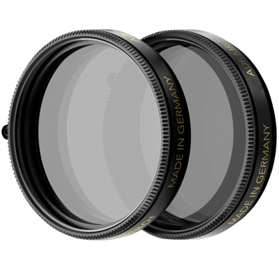
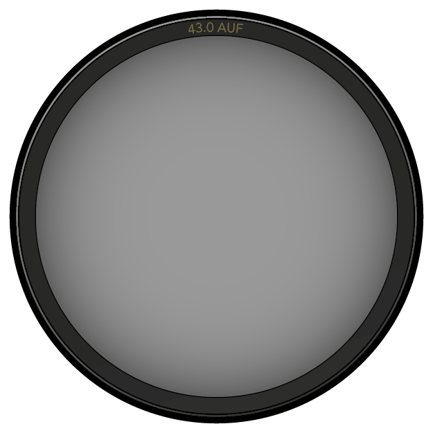
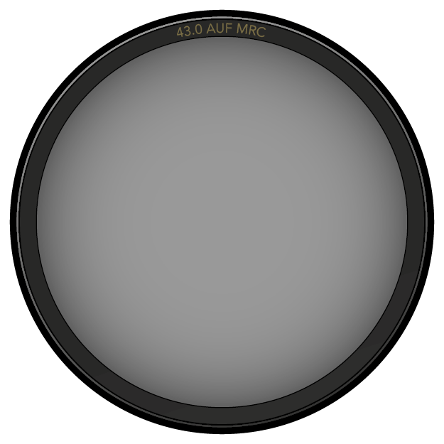
The IF AUF and IF AUF MRC linear polarising filters are characterised by a high degree of polarisation. This results in a high extinction of the reflected light component in the visible light range (VIS, 420 nm to 750 nm). This suppresses unwanted reflections. The result is a better image and a higher level of contrast. Polarising filters can also make things visible that are otherwise invisible, such as tension in plastics. IF AUF filters are also available with an MRC coating to reduce reflections at the air-glass interface.
Where is polarizer filter used? In industry, polarizing filters are used in a variety of applications where polarized light is critical. For example, in imaging applications such as microscopy, polarizer filters are used to improve contrast and image quality by selectively blocking or transmitting polarized light waves. They are also used in LCD displays to control the polarization of light passing through the liquid crystal cells, enabling the production of high-quality, high-contrast displays.
Resolvingpower
In the NTSC transmission standard, each field contains 262.5 lines, and 59.94 fields are transmitted every second. Each line must therefore take 63 microseconds, 10.7 of which are for reset to the next line. Thus, the retrace rate is 15.734 kHz. For the picture to appear to have approximately the same horizontal and vertical resolution (see Kell factor), it should be able to display 228 cycles per line, requiring a bandwidth of 4.28 MHz. If the line (sensor) width is known, this may be converted directly into cycles per millimeter, the unit of spatial resolution.
Improve the performance and accuracy of your machines by using our optical filters. Reduce annoying reflections, minimize unwanted wavelengths, and increase the efficiency of your processes. Our filters are the key to the smooth and efficient operation of your industrial systems. They are durable and robust, ensuring long-term use.
Our test technology and quality assurance reflect our high quality standards. We use state-of-the-art technologies such as interferometers and 3D coordinate measurement technology to test the lenses we manufacture to ensure they meet the highest standards. Our ISO 9001 certified processes, metrology rooms and procedures ensure consistent and reliable production to meet our customers' high expectations.
Theatre Spotlight with Fresnel Lens, Barndoor, Colour Frame & Piggy-Back Plug - 500w/650w - BravoPro.
MTF s ( ν ) = e − 3.44 ⋅ ( λ f ν / r 0 ) 5 / 3 ⋅ [ 1 − b ⋅ ( λ f ν / D ) 1 / 3 ] {\displaystyle \operatorname {MTF} _{s}(\nu )=e^{-3.44\cdot (\lambda f\nu /r_{0})^{5/3}\cdot [1-b\cdot (\lambda f\nu /D)^{1/3}]}} where
R e s o l u t i o n = 2 g r o u p + e l e m e n t − 1 6 {\displaystyle Resolution=2^{{group}+{\frac {element-1}{6}}}}
For example, in a security or air traffic control function, the display and work station must be constructed so that average humans can detect problems and direct corrective measures. Other examples are when a human is using eyes to carry out a critical task such as flying (piloting by visual reference), driving a vehicle, and so forth.
Spectralresolution
Vidicons, Plumbicons, and image intensifiers have specific applications. The speed at which they can be sampled depends upon the decay rate of the phosphor used. For example, the P46 phosphor has a decay time of less than 2 microseconds, while the P43 decay time is on the order of 2-3 milliseconds. The P43 is therefore unusable at frame rates above 1000 frames per second (frame/s). See § External links for links to phosphor information.
In analog systems, each horizontal line is transmitted as a high-frequency analog signal. Each picture element (pixel) is therefore converted to an analog electrical value (voltage), and changes in values between pixels therefore become changes in voltage. The transmission standards require that the sampling be done in a fixed time (outlined below), so more pixels per line becomes a requirement for more voltage changes per unit time, i.e. higher frequency. Since such signals are typically band-limited by cables, amplifiers, recorders, transmitters, and receivers, the band-limitation on the analog signal acts as an effective low-pass filter on the spatial resolution. The difference in resolutions between VHS (240 discernible lines per scanline), Betamax (280 lines), and the newer ED Beta format (500 lines) is explained primarily by the difference in the recording bandwidth.
where the sensor has M×N pixels M T F s e n s o r ( ξ , η ) = F F ( S ( x , y ) ) = [ sinc ( ( M ⋅ c ) ⋅ ξ , ( N ⋅ d ) ⋅ η ) ∗ comb ( c ⋅ ξ , d ⋅ η ) ] ⋅ sinc ( a ⋅ ξ , b ⋅ η ) {\displaystyle {\begin{aligned}\mathbf {MTF_{sensor}} (\xi ,\eta )&={\mathcal {FF}}(\mathbf {S} (x,y))\\&=[\operatorname {sinc} ((M\cdot c)\cdot \xi ,(N\cdot d)\cdot \eta )*\operatorname {comb} (c\cdot \xi ,d\cdot \eta )]\cdot \operatorname {sinc} (a\cdot \xi ,b\cdot \eta )\end{aligned}}}
The spatial resolution of digital systems (e.g. HDTV and VGA) are fixed independently of the analog bandwidth because each pixel is digitized, transmitted, and stored as a discrete value. Digital cameras, recorders, and displays must be selected so that the resolution is identical from camera to display. However, in analog systems, the resolution of the camera, recorder, cabling, amplifiers, transmitters, receivers, and display may all be independent and the overall system resolution is governed by the bandwidth of the lowest performing component.
Our polarizing filters reliably reduce reflections. At the same time, high contrast is maintained and image quality is not compromised.
S ( x , y ) = [ comb ( x c , y d ) ∗ rect ( x a , y b ) ] ⋅ rect ( x M ⋅ c , y N ⋅ d ) {\displaystyle \mathbf {S} (x,y)=\left[\operatorname {comb} \left({\frac {x}{c}},{\frac {y}{d}}\right)*\operatorname {rect} \left({\frac {x}{a}},{\frac {y}{b}}\right)\right]\cdot \operatorname {rect} \left({\frac {x}{M\cdot c}},{\frac {y}{N\cdot d}}\right)}
Turbulence scales with wavelength at approximately a 6/5 power. Thus, seeing is better at infrared wavelengths than at visible wavelengths.
Visit us at any tradeshow or event we attend worldwide! Come with your challenge and let our experts help you find the perfect solution for your apllication.
The P-W 76 and P-W 64 polarizing films feature a high contrast (erasure) of 10,000:1 (P-W 76) and 40,000:1 (P-W 64), respectively. These films can be used to reduce interfering reflections in the visible range of 430 nm to 780 nm from reflective surfaces or to make stress patterns visible on transparent plastics. They are also used to enhance the contrast of images. The films can be cut into any shape using a laser cutter.
Our advice ranges from selecting the right filter to assisting with integration into existing systems. You can count on our experts to provide the best support and find the perfect solution. Our in-depth application knowledge and proven optical expertise enable us to provide customized solutions that combine mechanical robustness, reliability and the highest imaging accuracy.
CCD and CMOS are the modern preferences for video sensors. CCD is speed-limited by the rate at which the charge can be moved from one site to another. CMOS has the advantage of having individually addressable cells, and this has led to its advantage in the high speed photography industry.
The NBS 1952 target is a 3 bar pattern (long bars). The spatial frequency is printed alongside each triple bar set, so the limiting resolution may be determined by inspection. This frequency is normally only as marked after the chart has been reduced in size (typically 25 times). The original application called for placing the chart at a distance 26 times the focal length of the imaging lens used. The bars above and to the left are in sequence, separated by approximately the square root of two (12, 17, 24, etc.), while the bars below and to the left have the same separation but a different starting point (14, 20, 28, etc.)


 Ms.Cici
 8618319014500