
Acktar digital library: Science & Research - acktar
These stages incorporate piezoelectric elements in a variety of drive mechanisms. ORIC® stages incorporate piezo inertia drives that use "stick-slip" friction properties to obtain extended travel ranges. Our Nanoflex™ translation stages use standard piezo chips along with manual actuators. Elliptec® stages use resonant piezo motors to push and pull the moving platform through resonant elliptical motion. Our LPS710E z-axis stage features a mechanically amplified piezo design and includes a matched controller.
Thorlabs also manufactures the MTS25-Z8 Motorized Translation Stage, which features a built-in actuator and reduced overall package size.
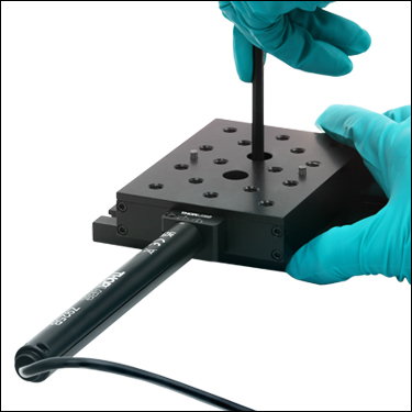
Thorlabs' PT1-Z9 (PT1/M-Z9) Single-Axis and PT3-Z9 (PT3/M-Z9) Three-Axis Motorized Translation Stages provide linear, orthogonal motion in one or three dimensions. Sixteen 1/4"-20 (M6) tapped holes allow easy integration with a wide variety of common optomechanical setups. The stages feature hardened steel linear bearings for precision motion and long life.
Objective lensfunction
Please note that this controller does not ship with a power supply. Compatible power supplies are listed below. Additional information can be found on the main KDC101 DC Servo Motor Controller page.
Screw the PT102(/M) Angle Bracket to the PT1-Z9 (PT1/M-Z9) Translation Stage, as shown above, using two 1/4"-20 (M6) cap screws. Then insert the two 1/8" alignment pins into the provided holes on the front face of the angle bracket for aligning the third and final stage.
Thorlabs' KDC101 K-Cube Brushed DC Motor Controller provides local and computerized control of a single motor axis. It features a top-mounted control panel with a velocity wheel that supports four-speed bidirectional control with forward and reverse jogging as well as position presets. A backlit digital display is also included that can have the backlit dimmed or turned off using the top-panel menu options. The front of the unit contains two bidirectional trigger ports that can be used to read a 5 V external logic signal or output a 5 V logic signal to control external equipment. Each port can be independently configured.
Functionofcondenserin microscope
Attach the second, orthogonal PT1-Z9 (PT1/M-Z9) Translation Stage, as shown above, using two 1/4"-20 (M6) cap screws. Then insert the two 1/8" alignment pins into the provided holes for aligning the angle bracket.
The motor cable that is built in to the Z925B actuator is 0.485 m (1.59 ft) long. If more length is required for your application, we recommend our PAA632 Extension Cable, which provides an additional 2.5 m (8.20 ft). It is sold at the bottom of this page.
The PAA632 Extension Cable provides an additional 2.5 m (8.20 ft) of cable length for the 15-pin D-type connectors used throughout our motorized actuator selection. The male end connects to the controller, while the female end connects to the motor.
The modular design of the PT series motorized translation stages allows the assembly of 2- or 3-axis stages within minutes. Each stage comes with two precision dowel pins that allow for right- or left-handed XY configurations with excellent orthogonality. Follow the steps below to build a 3-axis XYZ translator (PT3-Z9) from individual components.
The KPS201 power supply outputs +15 VDC at up to 2.66 A and can power a single K-Cube or T-Cube with a 3.5 mm jack. It plugs into a standard wall outlet.
For the Z925B motorized actuator, there are 512 encoder counts per revolution of the motor. The output shaft of the motor goes into a 67.49:1 planetary gear head. This requires the motor to rotate 67.49 times to rotate the 1.0 mm pitch lead screw one revolution. The end result is the lead screw advances by 1.0 mm.
Each axis requires a standalone controller unit and power supply to operate. For this purpose, we recommend our KDC101 K-Cube™ Motor Controller, which is described in more detail below.
The KCH301 and KCH601 USB Controller Hubs each consist of two parts: the hub, which can support up to three (KCH301) or six (KCH601) K-Cubes or T-Cubes, and a power supply that plugs into a standard wall outlet. The hub draws a maximum current of 10 A; please verify that the cubes being used do not require a total current of more than 10 A. In addition, the hub provides USB connectivity to any docked K-Cube or T-Cube through a single USB connection.
High powerobjective microscopefunction
The Kinesis Software features .NET controls which can be used by 3rd party developers working in the latest C#, Visual Basic, LabVIEW™, or any .NET compatible languages to create custom applications. Low-level DLL libraries are included for applications not expected to use the .NET framework and APIs are included with each install. A Central Sequence Manager supports integration and synchronization of all Thorlabs motion control hardware.
By providing this common software platform, Thorlabs has ensured that users can mix and match any of our motion control devices in a single application, while only having to learn a single set of software tools. In this way, it is perfectly feasible to combine any of the controllers from single-axis to multi-axis systems and control all from a single, PC-based unified software interface.
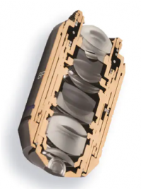
For instance, Olympus X Line objectives are packed with many ultra-thin convex and concave lenses to offer exceptional flatness, aberration correction, and numerical aperture in one lens system. The result? Bright, high-quality images throughout the field of view.
Objective lensmagnification
Knowledge is power when it comes to objective lenses. Many objective designs require you to make a tradeoff in one area of performance when you improve another. However, advances in objective technology enable our latest optical designs to overcome this common limitation.
These translation stages feature removable or integrated stepper motors and long travel ranges up to 300 mm. Many of these stages either have integrated multi-axis capability (PLSXY) or can be assembled into multi-axis configurations (PLSX, LNR Series, NRT Series, and LTS Series stages). The MLJ150 stage also offers high load capacity vertical translation.

Thorlabs' Motorized Translation Stages provide electronically controlled linear motion along a well-defined axis. The PT1-Z9 (PT1/M-Z9) Single-Axis Stage provides 25 mm (0.98") of travel along one axis, while the PT3-Z9 (PT3/M-Z9) Three-Axis Stage provides travel in three dimensions. Each stage is equipped with a 3.00" x 2.00" (75.0 mm x 50.0 mm) tapped hole matrix that includes sixteen 1/4"-20 (M6) taps for compatibility with standard optomechanics.
The PT102(/M) Right-Angle Bracket orients a PT1-Z9 (PT1/M-Z9) Single-Axis Stage in the vertical plane, allowing the construction of XY, XZ, or XYZ arrangements of PT1-Z9 stages. Two examples are shown to the right. This bracket is included with the purchase of a PT3-Z9 Three-Axis Stage. This angle bracket is also compatible with our manual and motorized MT series translation stages that offer 1/2" (25 mm) of travel. This allows stages with different travel ranges to be easily connected within the same mechanical system.
Thorlabs offers the Kinesis® software package to drive our wide range of motion controllers. The software can be used to control devices in the Kinesis family, which covers a wide variety of motion controllers ranging from small, low-powered, single-channel drivers (such as the K-Cubes™) to high-power, multi-channel benchtop units and modular 19" rack nanopositioning systems (the MMR60x Rack System).
What is objective lens in microscope
Here, we break down the anatomy of an objective lens into easy-to-understand terms and discuss the common parts that make up an objective.
Controller OptionsOur KDC101 K-Cube™ Motor Controllers are required to operate these stages. Each KDC101 provides control for a single axis, with or without a PC. It is bundled with Thorlabs' Kinesis® software, which supplies out-of-the-box stage control from a PC and enables support for common programming interfaces like LabVIEW, LabWindows, and ActiveX. A USB cable is included with the KDC101. Compatible power supply options are listed below.
Insert the two 1/8" alignment pins into the PT101(/M) Base and then screw it onto the PT1-Z9 (PT1/M-Z9) Translation Stage using the two included 1/4"-20 (M6) cap screws. Then insert the two 1/8" alignment pins into the provided holes to ensure orthogonality of the second stage.
Whatarethe3objectivelenses on amicroscope
These low-profile stages feature integrated brushless DC servo motors for high speed translation with zero backlash. When no power is applied, the platforms of these stages have very little inertia and are virtually free running. Hence these stages may not be suitable for applications where the stage's platform needs to remain in a set position when the power is off. We do not recommend mounting these stages vertically.
Stagemicroscopefunction
Thorlabs' motorized linear translation stages are offered in a range of maximum travel distances, from a stage with 20 µm of piezo translation to our 600 mm direct drive stage. Many of these stages can be assembled in multi-axis configurations, providing XY or XYZ translation. For fiber coupling applications, please see our multi-axis stages, which offer finer adjustment than our standard motorized translation stages. In addition to motorized linear translation stages, we offer motorized rotation stages and goniometers. We also offer manual translation stages.
Screw the third PT1-Z9 (PT1/M-Z9) Translation Stage to the front of the PT102(/M) Angle Bracket, using two 1/4"-20 (M6) cap screws.
The moving platform contains holes for alignment pins that ensure orthogonality when the stage is stacked with other stages or connected to our accessories. Horizontal loads of 20 lbs (9 kg) and vertical loads of 7 lbs (3.2 kg), when the motor is pushing down, or 10 lbs (4.5 kg), when pushing up, are supported by the actuator's inline 67.49:1 planetary gear head. Since the PT3-Z9 (PT3/M-Z9) Three-Axis Stages have the vertical actuator pushing down, the vertical load for these is 7 lbs (3.2 kg). The stages feature hardened steel linear bearings for precision motion and long life.
To begin the assembly process, insert the two alignment pins provided with the PT1-Z9 stage into the stage's alignment holes. Then position the bracket's alignment holes above the pins. The bracket can be fastened down using two 1/4"-20 (M6) cap screws. At this point, the bracket's vertical mounting surface will accommodate a stage that is attached horizontally (for XY configurations) or vertically (for XZ or XYZ configurations). For details, please see the XYZ Assembly tab.
In addition to these core components, some objectives include a spring-loaded retractable assembly to protect the front lens elements and specimen from collision damage.
While objective designs vary based on factors like their intended purpose, microscopy method, aberration correction, and manufacturer, all microscope objectives share some similar characteristics. Here are four common components to know:
The objective lens is one of the most important parts of a microscope, since it determines its basic performance and function. Yet, these precision pieces of optical equipment are often not well understood.
Rebecca holds a bachelor's degree in journalism from Endicott College and writes about trends and technologies in science and industry. She works closely with Evident engineers and scientists to write pieces about the latest laser scanning, super-resolution, multiphoton, upright, stereo, and inverted microscope systems, as well as leading-edge optics, cameras, and software. Follow her work to learn about Evident's latest for numerous applications, including cytology, pathology, education, and more.
Keep in mind, objectives with more optical corrections for aberrations and flatness typically contain many lenses. For instance, sophisticated plan-apochromatic objectives have about 15 lens elements—while common achromatic objectives contain significantly fewer lenses.
Typesof objectivelenses
Mounting Adapters and Stage CombinationsThorlabs' adapter plates and brackets provide a convenient way to mount the PT1-Z9 on an optical table or breadboard and to combine several stages into XY, XZ, or XYZ configurations. Photos of these adapters in use are shown below. For information on constructing an XYZ configuration from individual components, see the XYZ Assembly tab.
The PT1-Z9 stage is designed for single-axis translation. For applications requiring XY motion, simply purchase two PT1-Z9 stages and stack them using the provided alignment pins to ensure orthogonality. If XYZ motion is desired, then we recommend the PT3-Z9 stage. In addition to alignment pins for all three axes, the PT3-Z9 includes a PT101(/M) Base Plate and a PT102(/M) Right-Angle Bracket. For more details on these accessories, please read below. Two oversized 1/4"-20 (M6) counterbores in each single-axis stage allow the stage to be directly attached to a mounting adapter (sold below) or a metric or imperial breadboard with user-supplied cap screws.
The PT101(/M) Base Plate is ideal for XY configurations or already assembled XYZ multi-axis configurations where the standard counterbores in the middle of the stages are obstructed. Although the PT1-Z9 (PT1/M-Z9) Single-Axis Stage sold above can be directly mounted to a breadboard or optical table, mounting requires unobstructed access to the two bores in the middle of the moving platform. This base plate allows an attached stage to be positioned on a breadboard without having to disassemble a setup that already exists on the moving platform. This plate is included with the purchase of a PT3-Z9 (PT3/M-Z9) Three-Axis Stage.
The software package allows two methods of usage: graphical user interface (GUI) utilities for direct interaction with and control of the controllers 'out of the box', and a set of programming interfaces that allow custom-integrated positioning and alignment solutions to be easily programmed in the development language of choice.
Included and Compatible ActuatorsThe included Z925B DC servo actuator features a 485.0 mm (1.59 ft) cable length, an internal limit switch to prevent travel outside of the intended range, and an encoder that provides 29 nm resolution (see the Specs tab for additional details). This actuator attaches to the stage using a flexure clamp that tightens around the Ø3/8" barrel. If desired, the Z925B actuator can be replaced by any manual or motorized 25 mm (0.98") actuator that includes a Ø3/8" barrel, including stepper motor actuators and manual micrometers.
The bottom of the translation stage is connected to the base plate using two 1/4"-20 (M6) cap screws. The base plate includes two alignment holes for the alignment pins included with the PT1-Z9 stage, which together ensure that the translation axis is parallel to the plate.
Thorlabs offers linear translation stages with removable or integrated DC servo motors. These stages feature low profiles and many can be assembled in multi-axis configurations.


 Ms.Cici
 8618319014500