
Absorption of Light - absorb light
Oct 7, 2002 — Sensors (CCD / CMOS) are often refered to with an imperial fraction designation such as 1/1.8" or 2/3", this measurement actually originates ...
As far as I know for color images, the only possible improvement to the size of the Airy disk for a given lens aperture is in the special situation of transparencies - the size of the airy disk can be decreased by a factor of 2 with a special lighting setup and a bit further using oil immersion - these techniques alter the numerical aperture of the whole optical system, instead of just the lenses'.
What we refer to as the Diffraction Cutoff Frequency requires a much narrower aperture setting than the DLA for a specific sensor (or film - the size of the grains in various films affects the DLA with film!).
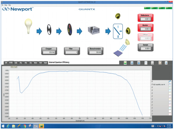
The acquisition and controls software for these QE solutions is pre-installed on a laptop computer which is included with the measurement system. The software uses an intuitive, icon based graphical interface to provide instrument controls, configuration, and data acquisition. The software seamlessly controls all of the system components. EQE and IQE curves are calculated and plotted as a function of wavelength in a single scan without the need to reposition the detectors or sample, optimizing measurement accuracy and repeatability. There is also an integrated, software-controlled sample voltage bias feature, which allows users to adjust from -10 to +10V.
As the title says, can the diffraction limit be overcome with superresolution techniques? Or is this the absolute hard limit in optical photography without making special assumptions? If this is the hard limit, what is an illustration of why this is the case?
Photoelectric conversionefficiency
(Sidenote: With today's fill factors of close to 100%, the achievable resolution increase is limited. This is because we are sampling with a rectangular window instead of a single point, but I couldn't find an authoritative source on the limit and have not worked out the math myself yet.) See below - Theoretical foundations
365 nm sale uv light. Amazon Everbeam 365nm 50W UV LED Black Light High. uvBeast Black Light UV Flashlight V3 365nm FILTERED Ultraviolet HI.
The QuantX-300 features a patent-pending summed Si/Ge detector design to provide a seamless, wide wavelength range. With traditional systems, two different detectors are needed to cover the wavelength ranges of Silicon and Germanium, requiring operators to stop scans and change detectors while scanning over the whole wavelength range. With the QuantX-300, continuous scans from 325 to 1800 nm can be accomplished without swapping detectors, saving time and removing the possibility of having the wrong detector in place. Our IQE-200B utilizes only a Silicon detctor, however Newport can upgrade this system to include a summed Si/Ge detector design – contact us for more information.
Mar 30, 2008 — Then, you can use the thin lens formula to calculate an estimate of the focal length. I hope these suggestions help you in designing your ...
"Without making special assumptions" in this case means the techniques of superresolution microscopy - structured light, laser beams etc.
UPDATE Thank you for your answers. However it feels to me more like you explained to me what diffraction means rather than if it is possible to overcome the diffraction limit under reasonable assumptions. To clarify further: In a relatively controlled environment, where you can expect the subject to be stationary and the lens/aperture diffraction to be the limiting factor of resolution (as opposed to sensor resolution), do techniques exist to increase detail beyond this diffraction limit without the aforementioned "special assumptions"?
Every point in the photographed scene can be understood as a single dirac pulse - from a spectral view, a dirac pulse contains all frequencies equally (|F(f)| =const.).
Externalquantum efficiency
We are proud to house and manage one of the few commercial photovoltaic and calibration test laboratories in the world. The Photovoltaic Calibration and Test Laboratory is accredited by A2LA to the ISO/IEC 17025 Standard, using state of the art equipment for measurements in accordance with ASTM E948 and E1021. The lab welcomes requests for prototype PV device performance measurements or PV reference cell calibrations. Flexible scheduling and rapid turnaround time ensure minimal downtime to time sensitive devices.
There are many possible approaches. One is simply blocking out the centre of your optical system and only using the edges. The central peak of the transfer function of this is narrower than for a circular aperture so your resolution is increased but you both have less signal received and have wider wings in the transfer function, both reducing signal to noise.
Choose products to compare anywhere you see 'Add to Compare' or 'Compare' options displayed. Compare All Close
Now add the sensor to the equation. The sensor consists of many rectangular photosites and for modern image sensors let's assume pixel pitch equals pixel size (e. g. 100% fill factor). Each of these squares has a frequency spectrum of $$|F(f)| = \frac{1}{X_{pixel}}sinc(f \frac{1}{X_{pixel}})|$$. However, the spatial frequencies that lie beyond half the pixel pitch will become visible as aliasing in the image - to avoid this, we need to shrink the distance of the pixels down to the point that sufficiently much of the information in the airy spectrum remains in the pass-band of the sensor. Practically however we cannot create pixel pitches smaller than the pixels themselves. They cannot overlap, right?
Considering the 2D case, we also have to look at the shape of the aperture and the pixels - to say it in the words of Sepp Herberger: "The round must go in the square", where the round is the image of the aperture - the airy disk and the square is the pixels. But for the moment, this will be left as an excercise for the reader ;)
We are proud to house and manage one of the few commercial photovoltaic and calibration test laboratories in the world. The Photovoltaic Calibration and Test Laboratory is accredited by A2LA to the ISO/IEC 17025 Standard, using state of the art equipment for measurements in accordance with ASTM E948 and E1021. The lab welcomes requests for prototype PV device performance measurements or PV reference cell calibrations. Flexible scheduling and rapid turnaround time ensure minimal downtime to time sensitive devices.
While the legacy QEPVSI-B system is no longer available for ordering, contact your Newport representative for more information on ordering a special variant of this measurement system, utilizing our CS260B series of monochromators. Please see the legacy product datasheet and operational guide, to see if this alternative solution would be an ideal fit for your application.
But we can get more information on the shape if we create multiple exposures that are ever-so-slightly shifted, effectively creating virtual pixels of a smaller size when we apply our math appropriately.
So in essence, the frequencies present behind the lens are the result of the interplay between the airy disk given as a function of f-number, the photosite size and the pixel pitch $$ sinc^2(\mathrm{aperture}), sinc(X_{\mathrm{pixel}}), DiracComb(X_{\mathrm{pitch}})$$.
Well, as you mentioned, it requires a non-moving subject, that's one of the limits of applicability. As John stated in his answer, you are using the temporal-based certainty (i.e., there is no motion in the scene, so it exists independent of time) to take multiple images (which takes time, but who cares, you have plenty of it when the subject isn't moving) that help you increase your spatial information / knowledge about the scene.
Our Quantum Efficiency Systems have been integrated with the redesigned Cornerstone 130B monochromator, providing upgraded performance while maintaining the same overall system platform. These solutions empower researchers to measure Internal Quantum Efficiency (IQE) and External Quantum Efficiency (EQE), also known as Incident Photon to Charge Carrier Efficiency (IPCE), for any photovoltaic device. Employing industry leading, durable components for optical performance, these systems are preconfigured, assembled, and calibrated at the factory. The products are a turn-key solution which includes all necessary components with integrated light source, monochromator, detectors, electronics, software, and even the computer.
Spectral response
Our Quantum Efficiency Systems have been integrated with the redesigned Cornerstone 130B monochromator, providing upgraded performance while maintaining the same overall system platform. These solutions empower researchers to measure Internal Quantum Efficiency (IQE) and External Quantum Efficiency (EQE), also known as Incident Photon to Charge Carrier Efficiency (IPCE), for any photovoltaic device. Employing industry leading, durable components for optical performance, these systems are preconfigured, assembled, and calibrated at the factory. The products are a turn-key solution which includes all necessary components with integrated light source, monochromator, detectors, electronics, software, and even the computer.
The resolution limits are extensively studied in microscopy, so it is useful to look at the techniques developed there. However, all the techniques that provide resolution beyond the diffraction limit are not applicable to form a natural color image and without altering the subject.
For more on how the DLA is affected by the resolution limits of the recording medium, please see: Does sensor size impact the diffraction limit of a lens?
While the legacy QEPVSI-B system is no longer available for ordering, contact your Newport representative for more information on ordering a special variant of this measurement system, utilizing our CS260B series of monochromators. Please see the legacy product datasheet and operational guide, to see if this alternative solution would be an ideal fit for your application.
These products leverage Newport's expertise in optical design, spectroscopy, precision motion control, and electronics technologies. These proficiencies have been focused into a complete, sophisticated measurement system for Quantum Efficiency (EQE and IQE). Both systems incorporate a patented detector geometry using a beam splitter, allowing for simultaneous measurement of EQE and the reflective losses to quantify IQE. Unique to these models are a sample stage with an integrated vacuum chuck and thermistor. They also include 4-wire sense measurement option which broadens the capabilities to include a large range of sample sizes and efficiencies.
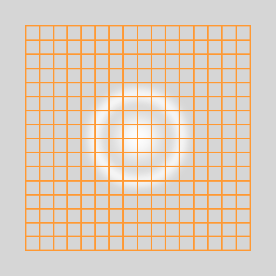
Passing this through an ideal but finite-sized aperture leads to a low pass filtering - the single point gets projected onto a less sharp image we call the Airy disk - whose frequency spectrum follows the square of the sinc function (|F(f)| ∝ sinc^2(f)). So this attenuation of higher frequencies is the fundamental limit in resolution for a given optical setup.
Common super-resolution techniques that can be used in this setting today try to increase the resolution by recovering the original image that we can only sub-sample with our limited sensor resolution (combining multiple slightly offset images) and/or modelling the imperfections of the optical system that prohibit it from reaching the diffraction limit. Another concept worth mentioning here is apodization, but this does not overcome the diffraction limit but merely removes the non-central maxima of the Airy disk.
Line Up ... Counterweight x Closer? What's that? Closer is currently the most exciting Techno party in Milan, taking place one Saturday every month during the ...
What we often refer to as the Diffraction Limited Aperture (DLA) for a specific digital sensor is the aperture at which the effects of diffraction are noticeable when the resulting image file is viewed at a magnification that yields 1-pixel in the image file equals 1-pixel on the monitor and those individual pixels are right at the limits of the viewer's perception to differentiate them. The DLA is the point at which the effects of diffraction are barely perceptible at such a magnification. This begins to occur when the size of the blur caused by diffraction becomes larger than the size of a digital camera's sensor pixels.
量子效率
Newport offers a variety of accessories, sold separately, to provide a complete measurement station including: Temperature controlled vacuum chuck Light biasing Electrical probing Water chiller Vacuum pump (110 or 220 VAC) Light Tight Enclosure for QuantX-300 Optical tables, workstations and breadboards (IG-23-2 industrial grade honeycomb core breadboard is recommended)
There shall be only one maximum sized dig per 20mm of diameter. Thus, if two maximum-sized digs are separated by less than 20mm, the part will not meet the ...
Detectivequantum efficiency
Buy & sell used lens mount adapters at KEH Camera. Save up to 40% off retail price and get a 180-day warranty! Financing options available.
But if you can increase the size of the pixels while still packing the same number of pixels in the same area, you can "push back" the diffraction limit a bit farther. And that's what sub-pixel shifting of the image sensor does.
quantumefficiency中文
Sort of, to a limited degree. Using sub-pixel shifting of the imaging sensor, in effect you are increasing each pixel size while keeping their spacing the same. Of course, it is not physically possible to build sensors where individual pixels are larger than their pitch (center-to-center spacing). But mathematically, this is basically what's happening.
The QuantX-300 features a patent-pending summed Si/Ge detector design to provide a seamless, wide wavelength range. With traditional systems, two different detectors are needed to cover the wavelength ranges of Silicon and Germanium, requiring operators to stop scans and change detectors while scanning over the whole wavelength range. With the QuantX-300, continuous scans from 325 to 1800 nm can be accomplished without swapping detectors, saving time and removing the possibility of having the wrong detector in place. Our IQE-200B utilizes only a Silicon detctor, however Newport can upgrade this system to include a summed Si/Ge detector design – contact us for more information.
... MtF: A subreddit devoted to transgender issues pertaining to male-to-female or trans feminine people ... r/MtF ... What's going on? I heard that speaker forbid ...
Yes but you are trading one type of information for another - it doesn't break the laws of physics or information theory. You have to assume the object is stationary and you are trading signal to noise for resolution.
As Michael Clark stated in his answer, a camera system is diffraction limited when the size of the Airy disk (the blur) caused by diffraction becomes larger than the size of a digital camera's sensor pixels.
Stack Exchange network consists of 183 Q&A communities including Stack Overflow, the largest, most trusted online community for developers to learn, share their knowledge, and build their careers.
Enter pixel-shift. With pixel shift, even though the individual pixels stay the same and each individual pixels spectral transform remains the same, taking multiple shots of the same subject with sub-pixel shifts allows us to decrease the pixel pitch beyond the physical distances. If we halve the pixel pitch, we double the aliasing frequency.
Solar panelefficiency
To illustrate the point: Can superresolution beyond the diffraction limit be achieved by taking multiple exposures from slightly different angles and positions and feeding them into [SR approach here]? Even with the added assumption of a diffraction-limited system (High resolution camera and lens)?
The size and nature of the Airy disk is not something you can overcome — it's a function of the wave-like behavior of light, the aperture size (usually assumed to be circular), and the wavelength of the particular light in question).
(Note: This section still needs work in terms of readability and clarity, but it also has become mostly redundant after finding the wikipedia article on optical resolution)
These products leverage Newport's expertise in optical design, spectroscopy, precision motion control, and electronics technologies. These proficiencies have been focused into a complete, sophisticated measurement system for Quantum Efficiency (EQE and IQE). Both systems incorporate a patented detector geometry using a beam splitter, allowing for simultaneous measurement of EQE and the reflective losses to quantify IQE. Unique to these models are a sample stage with an integrated vacuum chuck and thermistor. They also include 4-wire sense measurement option which broadens the capabilities to include a large range of sample sizes and efficiencies.
All camera optics are plagued by twin demons of interference and diffraction. These yield stray light rays that comingle with the image forming rays. Diffraction is caused when light rays from the vista being imaged, just brush by the edge of the aperture stop. Some close passes are shadowed but not completely blocked. The ricochets comingle and degrade the image. Interference is due to the wave nature of light crossing paths and adding and canceling each other.
Even with an optically perfect lens, the resolution will always be limited by the Rayleigh Criterion as pointed out by the other answers (if no other limits like e.g. lens imperfections lower our resolution further).
Several post-processing techniques that increase the resolution limits of a camera/lens system can be used to ameliorate the effects of diffraction. Stacking multiple images taken from slightly different positions as you suggest is one way. A tool such as Canon's Digital Lens Optimizer that uses very detailed lens profiles is another.
Optical Cast Infrared (IR) Longpass Filters ideal for blocking visible light, while passing near infrared wavelengths are available at Edmund Optics.
The acquisition and controls software for these QE solutions is pre-installed on a laptop computer which is included with the measurement system. The software uses an intuitive, icon based graphical interface to provide instrument controls, configuration, and data acquisition. The software seamlessly controls all of the system components. EQE and IQE curves are calculated and plotted as a function of wavelength in a single scan without the need to reposition the detectors or sample, optimizing measurement accuracy and repeatability. There is also an integrated, software-controlled sample voltage bias feature, which allows users to adjust from -10 to +10V.
HIMA DIGPER UNUSA. @himadigperunusa2859. 267 subscribers•17 videos. More about this channel ...more ...more. Subscribe.
However consider now that we massively increase our sensor resolution (or we can pixel shift to that effect), then we sample the Airy disk so much that we can perfectly reconstruct its true shape. We cannot know however what the true shape of the object is that creates the Airy disk - it might be as small as a single nanometer-sized photon source, but its image is never smaller than this blob of a few microns in diameter.
Internalquantum efficiency
Diffraction is a lot like the edges of depth of field. The more we magnify an image the easier it is to see. Diffraction starts at apertures where only very high magnification will reveal any effects at all. As the aperture is closed down further the effects begin to be perceptible at lower and lower magnifications.
His calculations, remain valid. We are talking about the resolving power of a lens system. Following is a table for 589, about the center of our color spectrum.
Scan Lenses, such as F-Theta Scanning Lenses, are designed to focus a laser beam onto a planar image plane for scanning and engraving.
Yes, opt-in. By checking this box, you agree to receive our newsletters, announcements, surveys and marketing offers in accordance with our privacy policy

For an Airy disk that results from a given aperture we can take a look at two extreme cases. In the first case we have a sensor that has a significantly higher pixel pitch than the size of the Airy disk. In this case, we severely subsample the Airy disk and only know that there is a blob of light hitting a single pixel, but nothing about its shape.


 Ms.Cici
 8618319014500