
Absorption (electromagnetic radiation) - what is absorption of light
McClatchey, R. A. & Selby, J. E. A. Atmospheric Attenuation of Laser Radiation from 0.76 to 31.25 μm. (U.S. Air Force Cambridge Research Laboratories, Bedford, Mass, 1974).
Wheeler, N. V. et al. Low-loss and low-bend-sensitivity mid-infrared guidance in a hollow-core–photonic-bandgap fiber. Opt. Lett. 39, 295–298 (2014).
(b) For an OAM-based MDM system, the pointing error could additionally induce inter-channel crosstalk as the aperture might fail to fully capture the phase changes and induce modal power coupling42,45. This could require more advanced pointing accuracy. Although the conditions are somewhat different, an illustrative example of a pointing error <3 μrad transmitter pointing error could cause ~1 dB power penalty for an OAM-multiplexed system with a 1.5 cm transmitted beam radius and 2.25 cm receiver aperture radius over a 100 m propagation distance for a C-band wavelength42.
In a very simple form, the ideal light microscopy experiment can be viewed as optimizing the competing properties of image resolution (in the XY or lateral direction as well as the Z or axial dimension), imaging speed (and/or acquisition time), and the amount of signal collected from the fluorescing sample (Figure 1). This is bounded by the limits imposed by photo-bleaching and/or photo-toxicity. In many experiments, light levels at the diffraction limited spot (focused by the objective) can be very high. This can lead to destruction of the fluorophore and unwanted biological consequences leading to cell death or changes in the physiology of the cells or tissue being illuminated. Given these constraints, these variables are difficult to balance and require careful attention to detail and systematic empirical testing. On top of these basic variables other secondary variables also can become important such as the cost of the necessary equipment and the difficulty of the technique.
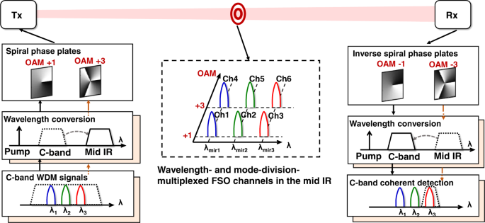
Mid-IR WDM signals are generated by wavelength converting C-band signals using the difference-frequency generation (DFG) process, and detected at the C-band after being converted via another DFG process. Mid-IR OAM beams are generated by passing mid-IR Gaussian beams through spiral phase plates (SPPs), and converted back to Gaussian beams using SPPs of inverse orders.
Malacarne, A. et al. Optical multicasting of 16QAM signals in periodically-poled lithium niobate waveguide. J. Lightwave Technol. 31 1797–1803 (2013).
Raghunathan, V., Borlaug, D., Rice, R. R. & Jalali, B. Demonstration of a mid-infrared silicon Raman amplifier. Opt. Express 15 14355–14362 (2007).
Gailele, L. et al. Multiplexing of spatial modes in the mid-IR region. Laser Resonators Microresonators Beam Control XIX 10090 100900Z (2017).
In summary, as is shown in table 1, the main advantage of TPFM is the depth of imaging (hundreds of microns) into the sample. Another important advantage is that the bleaching and phototoxicity are limited to the focal plane, however in the focal plane the damage can be greater due to the higher light intensities (mW compared to μW in confocal) needed for TPFM. TPFM typically requires the same time frame for acquisition as traditional CLSM (on the order of 1s/frame). One big disadvantage is cost due to the need for a point-scanning microscope and a tunable pulsed Ti:Sapphire laser. This cost increases substantially if one also adds a pre-compensation unit to correct dispersion in excitation pulse lengths or selects higher power lasers whose gain enables lasing at the hard to tune to regions approaching 700nm or somewhat above 1000nm.
Free-spaceopticaltransceiver
(4) In general, the pointing error might cause both angular tip/tilt and lateral displacement of the received beam42,43,44,45. There have been reports that investigated C-band FSO system performance under different pointing error42,43,44,45, and we believe mid-IR FSO systems could potentially share similar behavior43. Specifically:
(ii) In our demonstration, we multiplex three wavelength channels, which might be mainly limited by the PPLN phase-matching bandwidth. To scale the number of wavelength channels in our scheme, a nonlinear device with a wider phase-matching bandwidth might be required. Recently, mid-IR generation in nonlinear devices with wide phase-matching bandwidth have been reported (e.g., 700 nm phase-matching bandwidth of the thin-film lithium niobate by dispersion engineering32).
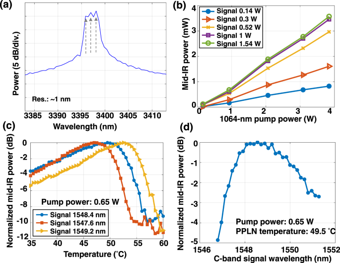
We experimentally demonstrate a mid-IR WDM and OAM-multiplexed FSO communication link using the setup illustrated in Fig. 2 (for a detailed description, see the Methods section). First, we measure the link performance of a WDM system with the mid-IR Gaussian beam. As shown in the spectrum depicted in Fig. 3(a), three WDM channels at the ~3400 nm wavelength (3.396, 3.397, and 3.398 μm) with a channel spacing of 27.5 GHz (~1 nm @ 3400 nm) are generated through the DFG process. We set the channel spacing of 27.5 GHz by tuning the frequency of the three C-band lasers used at the transmitter. However, the spectral shapes of the channels are not completely resolved by the optical spectrum analyzer (OSA) for the mid-IR, as the OSA has a limited resolution bandwidth of 1 nm which is wider than the data channels themselves. The pump and C-band signal power, as well as the PPLN1 temperature control, are adjusted to optimize the conversion efficiency of the mid-IR beam generation. Figure 3(b) shows the power of the generated mid-IR beam as a function of the pump power for different signal power values. The PPLN1 temperature is 49.5 °C for Fig. 3(b). The mid-IR power generally increases with the pump power. It also increases with the signal power but tends to saturate at signal power levels higher than 1 W. This might be due to an imbalance between the signal and pump photon numbers, possibly resulting in pump depletion23. Figure 3(c) shows the mid-IR power as a function of the PPLN temperature for three C-band signal wavelengths. The mid-IR power is measured by a free-space power meter with a sensor covering 0.19–20 μm wavelengths. The PPLN1 temperature is adjusted to satisfy the quasi-phase-matching in the DFG process. To determine the temperature that gives the optimal conversion efficiency for 1548.4 nm, the PPLN temperature is tuned by a temperature controller and the conversion efficiency is measured accordingly. As shown in Fig. 3(c), the optimal temperature is 49.5 °C for 1548.4 nm. When the C-band signal wavelength is longer, the optimal temperature tends to increase. When the pump power is 3.86 W and the PPLN1 temperature is 49.5 °C, the conversion efficiency is ~−26.5 dB, which is the ratio between the output idler power and the input signal power of the PPLN1. The conversion efficiency could decrease when the pump power is lower or the PPLN temperature is not optimal. The fact that there are different optimal temperatures for different C-band signal wavelengths could affect the conversion efficiency of the WDM channels. Figure 3(d) shows the generated mid-IR power as a function of the C-band signal wavelength when the PPLN temperature is set at 49.5 °C. The pump power at the PPLN1 input is ~0.65 W for Fig. 3(c, d). We note that the generated mid-IR power shown in Fig. 3(c) is normalized for each C-band signal wavelength; however, the generated mid-IR power in Fig. 3(d) is normalized for a fixed temperature value of 49.5 °C. Therefore, the normalized power values in Fig. 3(c) and (d) are not directly comparable. At a ~1.6 nm C-band signal wavelength bandwidth, the generated mid-IR power is >90% of the maximum generated mid-IR power. This allows for simultaneous wavelength conversion of a few WDM channels in a single PPLN waveguide. The wavelength conversion from the mid-IR to the C-band is performed in PPLN2. The total input power of all 3 mid-IR channels into PPLN2 is 0.956 mW, and the output power of all C-band channels is 0.0053 mW.
At the heart of the confocal microscope is the pinhole. When placed in the conjugate image plane to the point of focus on the sample it enables optical sectioning (Figure 3). The pinhole optically sections by acting as a barrier to light originating from other focal planes in the sample. Although the pinhole facilitates optical sectioning it must be understood that the axial resolution is still worse than the XY resolution (which is similar to WFFM). Axial resolution (Rz) in the confocal microscope is set by the expression:
Technical principals of Stimulated Emission Depletion (STED) microscopy. A. The combination of the normal excitation beam with the phase modulated STED beam produces a sub-diffraction emission spot. The images on the right in (A) show the doughnut pattern produced by the phase modulation of the STED beam. This beam when overlapped with the diffraction-limited excitation spot quenches emission where the beams overlap leaving the middle, sub-diffraction sized, spot for spontaneous fluorescence. B. Comparison of confocal (left) and STED (right) images reveals a marked increase in resolution by STED since more labeled particles are visualized. Scale bar, 500 nm. Figure reproduced with permission from (Willig et al., 2006b).
Thus, mixing a signal at ~1550 nm with a pump at 1064 nm results in an idler wavelength of ~3400 nm. Moreover, if the WDM channels are all in the phase-matching bandwidth of the PPLN waveguide, they can be simultaneously converted in the same PPLN waveguide. In addition to the wavelength degree of freedom, represented by WDM, OAM multiplexing is used to further increase data capacity. Mid-IR OAM beams are generated by passing the fundamental Gaussian beam through SPPs with different orders. At the receiver, an SPP with an inverse order is used to convert the corresponding OAM channel back to the Gaussian beam for signal detection and data recovery. Subsequently, the mid-IR Gaussian beam is mixed with a 1064-nm pump. A similar DFG process in another PPLN waveguide converts the mid-IR idlers to the C-band signals, with the wavelengths calculated as follows:11,12,13
Wang, J. et al. Terabit free-space data transmission employing orbital angular momentum multiplexing. Nat. Photon. 6 488–496 (2012).
In the last few years, many changes have been made to improve these microscopes, but the fundamental design for optical sectioning remains largely unchanged. Figure 3 shows a simplified diagram of the light path of an LSCM. This figure shows that laser light is directed to the sample through collimating and beam steering optics, scanning mirrors (which sweep the laser beam over the field of view) and an objective that focuses the light to a diffraction limited spot in the sample. Emission light from the sample is directed to light sensing detector(s) (typically photomultiplier tubes, also known as PMT's) through a pinhole that is in the conjugate image plane to the point of focus in the sample. After spatial filtering by the pinhole, the light is sensed by the detectors, and a proportionate voltage is produced and amplified and converted into digital levels for image display and storage.
a Spectrum of the generated mid-IR WDM signals with a resolution of ~1 nm. Arrows indicate the three mid-IR WDM channels. b Generated mid-IR beam power as a function of the 1064 nm pump power with different signal power values. The C-band signal wavelength is set at 1550 nm. c Generated mid-IR beam power as a function of PPLN temperature with different C-band signal wavelengths. d Generated mid-IR beam power as a function of C-band signal wavelength with a PPLN temperature of 49.5 °C.
In this demonstration, two OAM beams each contain three wavelength channels that are multiplexed, resulting in a total of six channels. The BER performance of the six channels is shown in Fig. 5(d). We receive one channel at a time in the proof-of-concept experiment. Considering a real communication system (M modes and N wavelengths), M×N parallel transmitters/receivers would be required to transmit/receive independent data streams. Each transmitter has a laser source and an IQ modulator, and each coherent receiver has a local oscillator laser. Moreover, at the transmitter, M PPLNs would be used to convert the wavelength of the signals, each with a mid-IR filter at the output. At the receiver, another M PPLNs would be used to convert the mid-IR wavelengths. In our experiment, SPPs and beam splitters are used to convert and combine the OAM beams. The MDM could also be potentially realized by other methods, which might be more efficient and more compact, such as multi-plane light conversion27 and Dammann gratings28. However, special designs might be required for them to work in the mid-IR region. The channels have slightly different performances, which could be due to the different crosstalk values of each channel. For all the channels, BER below the 7% FEC threshold can be achieved. This indicates that a total gross data capacity of 300 Gbit/s is transmitted through the mid-IR FSO communication system.
Pang, X. et al. 11 Gb/s LWIR FSO transmission at 9.6 µm using a directly-modulated quantum cascade laser and an uncooled quantum cascade detector. In: Optical Fiber Commun. Conference, Th4B.5, (Optica Publishing Group, 2022).
(vii) We wish to mention that eye safety is, in general, an important issue for FSO communication systems36. As one example under specific values of transmitter aperture diameter and exposure time, an eye safety standards document states that the total transmitted power should be <10 mW for wavelengths >1.4 μm37. We recommend consulting such standards documents when designing a mid-IR free-space communication system, such that the total power in the M×N data-carrying beams (i.e., M modes on each of N wavelengths) should be less than the recommended eye safety value36,37. For our demonstration, each of the six beams is ~0.3 mW, which we believe could be designed in the future to be within eye safety recommendations.
(1) The received signal could be attenuated due to atmospheric absorption by water vapor or other molecules5. This attenuation induces loss on the received mid-IR signal power and can degrade the OSNR and measured BER38. For comparison, many previous FSO demonstrations have used C-band wavelengths15,16,17,18,19, yet the 3–5 μm wavelength range could have a lower atmospheric attenuation (e.g., ~7% and ~11% attenuation after ~2 km sea-level horizontal propagation for ~3.4 μm and ~1.55 μm wavelengths under clear weather, respectively5). Such lower atmospheric attenuation in the mid-IR might result in a higher received signal power and a lower BER given the same link distance and transmitted signal power38.
Chou, M. H., Hauden, J., Arbore, M. A. & Fejer, M. M. 1.5-µm-band wavelength conversion based on difference-frequency generation in LiNbO3 waveguides with integrated coupling structures. Opt. Lett. 23 1004–1006 (1998).
Maximum projection reconstruction from confocal images obtained through a 65 μm stack of mouse cerebellum labeled with a combination of fluorescent proteins. In the online color version of this image one can see the unique colors produced and spectrally detected by the genetic combinations of individual fluorescent proteins which the authors label as XFP's. These colors were used to trace and map the various synaptic circuits. This figure was reproduced with permission from (Livet et al., 2007). This figure was originally published in color, and can be seen online in color, but has been altered for the print version of this article in black and white.
Free space opticalcommunication projects
a Measured beam profile of the mid-IR OAM beams. Intensity profile and interferogram with a Gaussian beam of the OAM + 1 and OAM + 3 beam, respectively. Intensity profile of the data-carrying multiplexed OAM + 1 and +3 beams. Intensity profile of the multiplexed OAM beam after passing through the second SPP with OAM order −3. b Normalized crosstalk matrix of MDM. c Measured BER of the OAM + 3 channel as a function of the received OSNR for the mid-IR OAM beam transmission when sending both OAM modes and sending a single OAM mode. d Measured BER and OSNR of all the channels, including two OAM modes with three wavelengths on each mode.
TPFM excitation is generated when a fluorophore absorbs two photons essentially simultaneously. This roughly doubles the amount of energy absorbed by the fluorescent molecules which drives their excited electrons to the same energy level as would the absorption of one photon at one-half the two-photon excitation wavelength (Fig. 6A). An example would be the excitation of GFP (typically excited around 488nm in a confocal experiment) at around 960nm using a pulsed laser. This is an oversimplification, as the actual TPFM absorption spectra for many fluorophores are over 100nm broad, and “selection rules” that govern the relative strengths of absorption bands vary between one-photon and two-photon excitation, but in most cases that is a good starting point for guessing where the maximal TPFM excitation occurs. The broad spectral absorption range of the typical two-photon fluorophore allows for multiple fluorophores in a sample to be excited at one wavelength simultaneously. Corresponding emission wavelengths for each fluorophores are then separated in different channels with the appropriate set of dichroic and emission filters or with spectral detection. The inherent optical sectioning ability of two-photon excitation occurs due to increased probability of two-photon absorption that occurs at the diffraction limited spot due to spatial energy crowding (Figure 6B). This can be seen in the equation for time averaged two-photon fluorescence intensity (If):
(a) For a Gaussian-beam, the mid-IR could possibly have lower turbulence-induced effects than the C-band because the phase distortion is potentially weaker for the mid-IR given the smaller phase delay for a certain propagation distance11,39. Such distortion can reduce the received signal power and increase the BER.
Figure 5(b) shows a normalized crosstalk matrix of the OAM multiplexed channels. The values in the crosstalk matrix indicate the measured optical power that is converted back to the C-band coherent receiver when a single mid-IR OAM beam is transmitted, and an inversed SPP is used to receive one OAM mode. The residual crosstalk between the OAM channels could be caused by the misalignment between the mid-IR beam axis and the center of the SPPs, which may degrade the quality of the generated OAM beams and the back-converted Gaussian beams.
In this article, we experimentally demonstrate a mid-IR FSO communication system using WDM, MDM, and a combination of WDM and MDM. As the proof-of-principle experiment, we demonstrate the multiplexing of multiple 50 Gbit/s QPSK channels in only a single domain as follows: (i) WDM only: three channels with different wavelengths on a single polarization near 3.4 μm (3.396, 3.397, and 3.398 μm) each carried by a single Gaussian beam and (ii) MDM only: two channels sent on two different OAM beams (+1 and +3) at a single mid-IR wavelength and on a single polarization. In addition, we show the compatibility of these individual multiplexing approaches and demonstrate WDM + MDM by transmitting six data channels on a single polarization located at three wavelengths with each carrying two beams on different modes. The operation is as follows: (i) at the transmitter, a C-band Gaussian beam is QPSK modulated, wavelength converted to the mid-IR by difference frequency generation (DFG)11,12,13 and then converted into an OAM beam by a spiral phase plate (SPP); and (ii) at the receiver, converting the OAM back to a Gaussian beam using a SPP and wavelength converting into the C-band using DFG11,12,13. According to the BER results, the OSNR penalties at the forward error correction (FEC) threshold are estimated to be: (i) ~2 dB for wavelength conversion; (ii) ~1 dB for wavelength multiplexing; and (iii) ~0.5 dB for inter-modal crosstalk. Compared with previous demonstrations of data-carrying WDM systems and OAM-based MDM systems15,16,17,18,19, we explore the data transmission/detection in the mid-IR wavelength region using the scenarios of WDM only, OAM-based MDM only, and a combination of both multiplexing techniques. By utilizing both multiplexing techniques and the wavelength conversions between the C-band and the mid-IR, we achieve the multiplexing of six data channels with a total capacity of 300 Gbit/s, corresponding to a ~30× increase in comparison to previous single-channel, single-beam mid-IR demonstrations7,8,9,10,11,12.
Yang, H., Yang, R. Q., Gong, J. & He, J.-J. Mid-infrared widely tunable single-mode interband cascade lasers based on V-coupled cavities. Opt. Lett. 45 2700–2703 (2020).
Xie, G. et al. Performance metrics and design considerations for a free-space optical orbital-angular-momentum-multiplexed communication link. Optica 2 357 (2015).
(i) In our approach, wavelength conversion is utilized to convert the signals between the C-band and mid-IR, such that widely available, high-performance C-band components can be used to enable high-speed data generation and detection. Although many native mid-IR devices are available (e.g., narrow-linewidth lasers29,30 and optical amplifiers31), high-speed mid-IR modulators and photodetectors are still not easily found but can be used when available.
Where δ2 is the two photon cross section for the fluorophore, η is the quantum yield of the fluorophore, P is the intensity (power) of the excitation light, τP is the pulse width of the excitation pulses, fP is the repetition rate of the laser, NA is the numerical aperture of the objective, h and c are Plank's constant and the speed of light respectively, and λexc is the wavelength of the excitation light (Diaspro et al., 2006). In fact, the probability of two-photon absorption decreases as the fourth power of distance away from this focal region along the z-axis (NA dependence) and increases as the square of the intensity (mW of power are typically required). Another variable is the temporal pulse width, τP, of the excitation light pulse as it reaches the sample. In general, short pulse widths (on the order of 100fs) are optimal for two-photon excitation.
Subsequently, 25 Gbaud QPSK signals are transmitted on each WDM channel. In the C-band generation/detection case, the signal generated by the C-band transmitter is directly received by the coherent receiver without wavelength conversion and free-space propagation. As shown in Fig. 4(c), the mid-IR cases have OSNR penalties compared to C-band generation/detection cases. These OSNR penalties might be caused by the wavelength conversions where (i) undesired terms might be generated by the PPLN and overlap with the mid-IR data channels leading to in-band crosstalk and (ii) additional frequency drift and phase noise from the pump laser might be added to the mid-IR data channels24. In both the single-channel and WDM cases, only mid-IR Gaussian beams are used, and the SPPs are bypassed. The received signal is coupled to a single-mode fiber and amplified by an erbium-doped fiber amplifier (EDFA) to compensate for the power loss. A variable optical attenuator (VOA) is used before the EDFA to change EDFA input power and the OSNR of the EDFA output. A C-band OSA is used to measure the OSNR of the signal. For the BER measurement, the signal into the coherent receiver has similar power and different OSNR values. This is achieved by (i) changing the EDFA input power by the VOA, (ii) changing the gain of the EDFA, and (iii) setting the received data channel power into the coherent receiver to 3 dBm. The noise figure of the EDFA is <4 dB. At the receiver, we use an EDFA to amplify the received signal, where the amplified spontaneous emission noise might be added. If the received signal power changes due to the free-space link loss, the OSNR of the EDFA output might change accordingly. We choose the BER-OSNR curve as a figure of merit to investigate the penalties caused by the wavelength conversion and crosstalk between multiplexed channels15. It might also be possible to use the BER vs. received mid-IR power as a figure of merit11. We find that the single-channel mid-IR Gaussian beam has a ~2 dB OSNR penalty at the BER near the FEC threshold of 7% overhead in comparison to the C-band generation/detection case. To help suppress crosstalk from adjacent channels, we use digital filtering in the receiver after coherent detection25. The mid-IR WDM channel has an additional ~1 dB OSNR penalty compared to the mid-IR single-channel transmission. We note that some of the measured power penalty might be due to crosstalk induced by the wavelength conversion in which undesired mixing terms might be generated by the PPLN and interfere with the mid-IR data channels24. Figure 4(d) shows the measured BERs as a function of the received OSNR for all three WDM channels. We note that the BER vs. OSNR curves in Fig. 4(c, d) are not completely smooth (i.e., there is some “wiggle” in the measurements). This could be due to measurement error of OSNR value, which might be induced by the power measurement error of the OSA.
Kaushal, H. et al. Experimental study on beam wander under varying atmospheric turbulence conditions. IEEE Photon. Technol. Lett. 23 1691–1693 (2011).
Thank you for visiting nature.com. You are using a browser version with limited support for CSS. To obtain the best experience, we recommend you use a more up to date browser (or turn off compatibility mode in Internet Explorer). In the meantime, to ensure continued support, we are displaying the site without styles and JavaScript.
There is growing interest in the mid-IR region for potential applications in communications, sensing, and imaging in both free space and fiber1,2,3. For free-space optical communication links, the mid-IR has several transmission windows that provide a relatively low atmospheric absorption in comparison to the C-band (1530–1565 nm)4. For example, it was reported that 3–5 μm and C-band wavelengths could have ~7% and ~11% atmospheric attenuation after 2 km sea-level horizontal free-space propagation with clear weather, respectively5. Moreover, mid-IR wavelengths tend to have better penetration through inclement weather conditions6. For example, it was reported that 3–5 μm and C-band wavelengths could have ~24% and ~40% atmospheric attenuation after 2 km sea-level horizontal free-space propagation with hazy weather conditions, respectively5. There have been reports of mid-IR communication systems that have used native mid-IR transmitters/receivers (e.g., quantum cascade lasers) to achieve up to 11-Gbit/s data rate using direct detection7,8,9,10. In these systems without wavelength conversion, the transmitter modulates data directly onto the mid-IR wavelengths and the receiver directly detects the data-carrying mid-IR wavelengths to recover the data7,8,9,10. There have also been reports of mid-IR communication systems that have used C-band devices and wavelength conversions11,12,13 to achieve 10 Gbit/s quadrature-phase-shift keying (QPSK) using coherent detection12,13. At the transmitter side, the data channels are modulated onto the C-band wavelengths, and these data-carrying wavelengths are converted to the mid-IR wavelengths by wavelength conversion. At the receiver side, the data-carrying mid-IR wavelengths are wavelength converted to the C-band, and these wavelengths are detected by the C-band receiver to recover the data11,12,13. Importantly, these transmission achievements have employed only a single data channel on a single beam.
Cho, C.-Y. & Chen, Y.-F. Compactly efficient CW 3 to 4.5 μm wavelength tunable mid-infrared laser in optically pumped semiconductor laser with intracavity OPO. IEEE J. Sel. Top. Quant. Electron. 28 1500206 (2022).
Prasad, N. S. Optical Communications in the mid-wave IR spectral band. Free-Space Laser Communications, 347–391 (Springer, New York, NY, 2005).
Viterbi, A. J. & Viterbi, A. M. Nonlinear estimation of PSK-modulated carrier phase with application to burst digital transmission. IEEE Trans. Inf. Theory 29 543–551 (1983).
Commercially available turn-key confocal systems usually consist of a modified point-scanning confocal microscope which includes a Ti:Sapphire pulsed laser (often automatically tunable over a broad range of wavelengths) and non-descanned detector channel(s). The non-descanned detector is a PMT mounted closer to the sample where the emission does not travel back through the scan-head. Since no pinhole is necessary, this configuration can be employed to reduce light losses that would occur if the emission light passed back through the scan-head. Typically, commercially available pulsed lasers produce approximately 100fs pulses at rate of 80mHz. Dispersion in the optics of the microscope and objective will lengthen these pulse widths by at least a factor of two. Recently, commercial lasers optionally include an additional unit for pre-compensation of this dispersion which can reduce the pulse length at the sample (which restores the two-photon fluorescence efficiency).
Bosco, G., Curri, V., Carena, A., Poggiolini, P. & Forghieri, F. On the Performance of Nyquist-WDM Terabit Superchannels Based on PM-BPSK, PM-QPSK, PM-8QAM or PM-16QAM Subcarriers. J. Lightwave Technol. 29 53–61 (2011).
Deconvolution fluorescence microscopy (DFM) is a form of WFFM. DFM requires prior knowledge of the point spread function (PSF, for more information on the PSF see (Coling and Kachar, 1997)) to allow optical sectioning. In this technique, multiple XY sections are imaged through the sample in the Z-dimension. The resulting stack of images, still lacking Z-dimension discrimination, are then analyzed using an empirical or idealized mathematical model of the PSF created by the microscope optics. This analysis results in a volumetric recreation of the sample in 3D space. DFM can also be used to enhance other techniques that are able to optically section such as confocal and two-photon microscopy (discussed below). Software for DFM is available commercially or through plug-ins for the free image analysis program ImageJ (http://rsbweb.nih.gov/ij/, NIH, Bethesda, MD). Although DFM is a powerful technique when used in capable hands (reviews include (Boccacci and Bertero, 2002; Wallace et al., 2001)), the novice user should be warned that optical sectioning is done indirectly using a mathematical model. Knowledge of the limitations of the model used for DFM is critical to understanding the images produced and interpretation of the data. Given these constraints it is beyond the scope of this paper and is not listed in Table 1.
Structured Light Microscopy (SLM) is a form of WFFM that enables optical sectioning. SLM works by inserting a moveable grid pattern into the optical path of the excitation light in the wide-field microscope. This produces a pattern in the images produced. The pattern is moved in the XY and even Z-dimension and the way that the detected fluorescence from the sample interacts with the pattern is then analyzed using a simple mathematical formula to create the optical sections (Figure 2). Many commercial systems are available for SLM and also moveable grating patterns are available for those wishing to modify existing WFFM microscopes. In the last few years SLM has been shown capable of producing super-resolution images (≈ half the diffraction limit) (Gustafsson, 2000; Schermelleh et al., 2008).
International Electrotechnical Commission. Safety of laser products - Part 12: Safety of free space optical communication systems used for transmission of information. (International Electrotechnical Commission, 2019).
Table 1 shows the main advantages and disadvantages of LSCM. The main advantage of LSCM is that one may optically section while still doing complex experiments. Another advantage is the versatility of imaging capabilities and types of experiments one can perform. Most of these systems have multiple channels for multi-color, variable pinhole sizing for selecting the desired optical section thickness (usually sacrificing z-resolution for signal intensity), and software for variable ROI (region of interest) selection. Another example would be the ability to separate spectrally overlapping fluorescent proteins with spectral detection and spectral deconvolution methods. In addition, these systems, particularly in the inverted microscope configuration, can accommodate both live cells or fixed cells or tissue. Many manufacturers also provide options for small stage incubation systems. These systems allow long term experiments, particularly when coupled to automated acquisition software that enables auto-focusing algorithms in tandem with precise XYZ stage movement. Disadvantages of a modern LSCM system include the relatively low scan speed (as the beam must be swept through each pixel in the field of view), the relative price, and the amount of light impinging on the sample. The flexibility of the LSCM does mitigate many of the disadvantages, and in many instances, one can balance the imaging conditions among the variables listed in figure 1 to get the most out of a given experiment. For instance, if full-frame imaging speed is too slow to capture a physiological event in a live cell experiment one might use a small ROI to increase temporal resolution. Despite this flexibility, one concern always remains and should be considered when conducting LSCM and that is keeping the light levels low enough to avoid killing or bleaching the sample.
Phillips, R. L. & Andrews, L. C. Spot size and divergence for Laguerre Gaussian beams of any order. Appl. Opt. 22 643 (1983).
Soibel, A. et al. Midinfrared interband cascade laser for free space optical communication. IEEE Photon. Technol. Lett. 22, 121–123 (2009).
The main disadvantages of the STED approach are the cost of the system and the amount of power that impinges on the sample (Table 1). The cost of the system is relatively high because two pulsed lasers are needed in addition to the already expensive laser scanning microscope system and very sensitive emission detectors (avalanche photo-diodes) required ( fast electronics and are sensitive in the far-red portion of the emission spectrum). Another disadvantage is the amount of power that is used for a STED system is high (tens of mW for the second beam). Since there is the potential for destruction of the probe or sample, only very photo-stable probes can be used. The list of probes that have been used to date are LDS721, certain ATTO dyes (AttoTech), and fluorescent proteins (Willig et al., 2006a). While the current commercial system can only improve lateral resolution, axial resolution can also be improved (Hell, 2007). It remains unclear how deep into tissue this technique remains effective. It is likely that that the loss of coherence of the shape of the STED beam with depth is a limiting factor and will be tissue dependant. In general, STED is most effective for fixed tissue as movement or diffusion of the fluorescent marker during scanned imaging will negate any gains in resolution.
Yao, A. M. & Padgett, M. J. Orbital angular momentum: origins, behavior and applications. Adv. Opt. Photon. 3 161–204 (2011).
free-spaceopticalcommunication pdf
The laser scanning confocal microscope (LSCM) remains a key piece of equipment in most imaging laboratories. Most modern LSCM systems offer a variety of advantages and are equipped with software to perform complex 3D (z-stack), 4D (z-stack over time), or even 5D (z-stack over time including spectral imaging) experiments. These microscopes often include software to facilitate data acquisition for complex methodologies such as spectral deconvolution, Fluorescence Recovery After Photobleaching (FRAP), and Fluorescence Resonance Energy Transfer (FRET). There have been many reviews written about confocal microscopy, but readers are encouraged to see the following texts for comprehensive information regarding all forms of confocal microscopy (as well as other microscopy techniques)(Hibbs, 2004; Pawley, 2006).
STED microscopy, developed by Stefan Hell and colleagues, is a relatively new super-resolution technique that has been shown to improve fluorescence microscopy resolution by approximately an order of magnitude over traditional diffraction limited techniques such as LSCM. STED can produce optical resolution to levels that were previously thought possible only with electron microscopy, and it has been used to examine key biological processes that no other technique could have examined (Kellner et al., 2007; Willig et al., 2006b). STED improves resolution by a direct reduction in the emission spot size by using a second laser beam (the STED beam) (Figure 7 and explained below). It is important to note that the improvement in resolution is done directly without the need for post processing and mathematical redistribution of the light, as is done in deconvolution microscopy or by combining multiple images that has taken with respect to a moveable grid pattern, as is done in structured light microscopy. STED is so straight-forward that to the user this seems like a normal point-scanning technique such as LSCM or TPFM. In fact, Leica Microsystems (Wetzlar, Germany) has now commercialized this system on their current point-scanning microscope stand.
This review is intended to expand and build-upon the last review of fluorescence microscopy in this series (Coling and Kachar, 1997) which provided a foundation for understanding fluorescence microscopy and the basics of immuno-labelling. In this review, knowledge of the basics of fluorescence microscopy (including wide-field microscopy) presented in that paper will be assumed. The object of this review is to provide non-expert microscopists a concise description and guide to select techniques that may have the widest appeal and that are, or will soon be, commonly used in most light microscopy core facilities or advanced biological research labs. The techniques to be reviewed encompass the most basic (such as wide-field fluorescence microscopy) to cutting edge techniques like Stimulated Emission Depletion (STED) microscopy. An emphasis will be placed on explaining the strengths and weaknesses of these techniques in terms of balancing the variables discussed in Figure 1. A table at the end of this review will summarize this discussion and should serve as a quick guide for choosing the appropriate imaging modality from among the techniques discussed.
Xu, M. et al. Dual-polarization thin-film lithium niobate in-phase quadrature modulators for terabit-per-second transmission. Optica 9 61–62 (2022).
At the receiver, the OAM beams are first de-multiplexed by SPPs of the corresponding inverse order (−1 for the OAM + 1 beam and −3 for the other beam). The SPP converts the corresponding OAM input to a Gaussian beam, while input OAM beams of other orders emerge as ring-shaped, center-null beams to be blocked by an appropriate spatial filter. The mid-IR Gaussian beam and a 1064 nm pump laser are coupled into PPLN2, which converts the mid-IR beam back to the C-band through the DFG process. At the PPLN2 output, a 1500 nm high-pass filter is used to filter out the high-power pump. The received signal is then coupled to a single-mode fiber and detected and processed by a C-band coherent receiver. The signal is amplified by an EDFA and filtered by a band-pass filter (with a bandwidth of ~1 nm and a tunable central wavelength) to suppress the out-of-band noise before being detected by the coherent receiver. For the crosstalk matrix measurement in Fig. 4(b), a band-pass filter (with a bandwidth of ~0.2 nm and a tunable central wavelength) is used. The output optical power of the local oscillator laser is 10 dBm. The optical signal power of the received data channel at the input of the coherent receiver is set to 3 dBm. The coherent receiver has a bandwidth of 40 GHz. The signal detected by the coherent receiver is sampled by an oscilloscope with an 80 GSa/s sampling rate and a 33 GHz bandwidth.
Lei, T. et al. Massive individual orbital angular momentum channels for multiplexing enabled by Dammann gratings. Light.: Sci. Appl. 4 e257 (2015).
As mentioned above, the decay of the evanescent wave is exponential to the distance above the coverslip. This relationship can be expressed as:
(v) In general, polarization-division-multiplexing (PDM) is potentially compatible with WDM and MDM, thereby offering another avenue for capacity increase15. In our current experimental setup, all channels are at a single polarization using the single-polarization IQ modulators at the Tx and polarization-sensitive PPLNs at the Tx and Rx. We believe that PDM can potentially be implemented in our approach, and some techniques that might help achieve this include: (a) Modulator: a dual-polarization IQ modulator to generate PDM signals34, and (b) PPLN: polarization diversity PPLN architecture to perform the wavelength conversions of the polarization-multiplexed signals35.
(vi) The results described in this paper are for free-space communications. However, many of the same principles for the transmitter and receiver should still be valid in an optical fiber communication system, and there is interest in low-loss fibers for mid-IR wavelengths1.
where h is the height of the SPP surface, φ is the azimuthal angle, l is the OAM order, λ is the mid-IR beam wavelength of ~3.4 μm, and n is the refractive index of the SPP. The SPP is made of Zinc Selenide, which has low absorption and a refractive index of ~2.4 in the mid-IR wavelength range. The measured insertion loss of the SPP is ~0.45 dB, which corresponds to >90% transmission50. Metasurface phase masks have also been used to impart phase profiles. Fabricated in an amorphous silicon on a sapphire platform51, they exhibited insertion loss of ~0.91 dB, which is slightly higher than that of the Zinc Selenide SPPs used in the current demonstration.
Advantages offree space opticalcommunication
Many of the microscope systems available from manufacturers have become very easy to run. While this provides easy image acquisition for many of the techniques listed in Table 1, the danger remains that an incomplete understanding of the fundamental physics and limitations of the techniques can result in wrong, incomplete, or biased data (as recently noted in (Pearson, 2007) ). It should be noted that Table 1 is only a rough guide to the commercially available fluorescence microscopy techniques and the reader should consult other sources to provide more complete understanding. There are many reviews available that are not listed here and many good web based resources such as Molecular Expressions: Exploring the World of Optics and Microscopy (http://www.microscopy.fsu.edu/), The Molecular Probes Handbook (http://probes.invitrogen.com/handbook/) and the Confocal Listserv (http://listserv.acsu.buffalo.edu/cgi-bin/wa?A0=CONFOCAL&D=0&F=P&T=0). One final note is that one must also be able to analyze the data one has collected. There are many good commercially available image processing software packages available as well as the comprehensive free program ImageJ (http://rsbweb.nih.gov/ij/). Last, the mention of any company producing microscopy related products in this work is in no way intended as an endorsement of them by the National Institutes of Health or the author.
Diagram of some of the critical opposing factors in an imaging experiment. The best image is one that can balance these factors to obtain the necessary information while avoiding photobleaching or phototoxic effects. Table 1 outlines how these factors differ between the various commercialized microscopy techniques discussed in this work.
Arnulf, A., Bricard, J., Curé, E. & Véret, C. Transmission by haze and fog in the spectral region 0.35 to 10 microns. J. Opt. Soc. Am. 47, 491–498 (1957).
We generate C-band WDM channels, as shown in Fig. 2, by modulating three laser sources with two optical in-phase-quadrature modulators, each loaded with a 25 Gbaud QPSK signal. The odd and even channels are generated from different modulators. Each IQ Mach-Zehnder modulator has two electrical inputs as the in-phase and quadrature signals. The signals are fed to a nested Mach-Zehnder interferometer (MZI) structure. The continuous-wave light input is split into two copies and modulated with the two electrical signals in the MZI structure. The quadrature signal experiences a π/2 shift before the superposition of the two light streams, and the IQ modulator has an electro-optical bandwidth of 25 GHz. The electrical signal is generated by an arbitrary waveform generator with a 92 GSa/s sampling rate. The electrical inputs are amplified by driver amplifiers with a bandwidth of 60 GHz before driving the IQ modulator. One branch is delayed so that the adjacent wavelength channels have decorrelated signals. The data channels are amplified with an EDFA (EDFA1) and coupled into a PPLN waveguide (PPLN1) with a 1064 nm pump laser, which is amplified with an ytterbium-doped fiber amplifier (YDFA). The C-band lasers (λ1, λ2, λ3) at the transmitter have a linewidth of ~100 kHz and output power of 10 mW. The 1064 nm laser has a linewidth of ~100 kHz and output power of 120 mW. Polarization controllers are used before the EDFA1 and YDFA to adjust the polarization of the beams into the polarization-sensitive PPLN. The total input optical power of the data channels before EDFA1 is ~0.5 mW. The output optical power of the amplified data channels after the EDFA1 is adjusted ranging from 0.14 to 1.54 W. The input optical power of the pump before the YDFA is ~10 mW. The output optical power after the YDFA is adjusted ranging from 1.5 to 7.5 W. The PPLN is temperature-controlled to adjust the quasi-phase-matching frequency and optimize mixing efficiency. A mid-IR beam is generated through the DFG process. At the PPLN1 output, two Germanium windows are used as mid-IR band-pass filters to filter out the high-power pump and input signals. The generated mid-IR fundamental Gaussian beam is split into two paths and transmitted through two SPPs with OAM orders of +1 and +3. The two OAM beams are combined, with one path delayed for data decorrelation. Subsequently, the combined beams propagate co-axially for ~0.5 m in free space.
In addition to cameras, wide-field microscopy has also been improved by better light filters, mirrors, and objectives. Commercially available filters, for instance from Chroma Inc (Rockinham, VT), (Omega Brattleboro, VT), or Semrock (Rochester, NY), have very high transmittance or reflection values enabled through new sputter-coating technologies. Also, these filters can have very sharp wavelength dependencies which enable multi-color discrimination. In the last decade, all of the major microscope companies (such as Leica, Nikon, Olympus, and Zeiss) have also improved microscope objectives. These new objectives have very flat fields (which decreases objective induced gradients in intensity across an image), long working distances with good resolving power, improved light transmission from the near UV to the infra-red, and are available in varieties that match the refractive index of the sample being imaged.
Similar to communications in optical and radio systems, multiplexing multiple independent data channels and transmitting them simultaneously has produced dramatic capacity increases. Key examples are frequency- and wavelength-division multiplexing in RF and optical systems, in which each channel occupies a different frequency or wavelength14,15,16. Specifically, wavelength-division-multiplexing (WDM) has been ubiquitously deployed in the conventional C-band wavelength15,16. However, to the best of our knowledge, we are not aware of reports demonstrating multiple-channel WDM transmission in the mid-IR.
Kaiheng Zou, Kai Pang, Hao Song, Zhe Zhao, Haoqian Song, Runzhou Zhang, Huibin Zhou, Amir Minoofar, Cong Liu, Xinzhou Su, Nanzhe Hu & Alan E. Willner
TIRF microscopy excites a shallow region above the coverslip using oblique laser excitation which is totally internally reflected and produces an evanescent wave for fluorophore excitation. A. Internal reflection. Light propagating through the periphery of a high numerical aperture objective (>1.38) is totally internally reflected by the coverslip and sent down the opposing side of the objective. B. Evanescent wave is formed when the critical angle θC is reached and the light is the totally reflected. The reflection at the coverslip is due to the oblique angle of illumination and the mismatch of refraction index (n) between the oil and coverslip. Note that the evanescent wave only excites fluorophores where the cell attaches or is touching the coverslip. C and D (no D indicated) show a wide-field and TIRF image, respectively, of GFP tagged myosin V from Drosophila embryo hemocytes. Comparing the two images it is evident where the Myosin 5 is closest to the coverslip particularly in the bottom cell. Hemocytes courtesy of Amy Hong, NHLBI, NIH. Figure B was reproduced with permission from Mike Davidson (Florida State University and the National High Magnetic Field Laboratory) and the Molecular Expressions website.
International Electrotechnical Commission. Safety of laser products - Part 1: Equipment classification and requirements. (International Electrotechnical Commission, 2014).
(a) For a Gaussian-based system, the pointing error could reduce the received signal power and increase the BER as the receiver aperture might fail to capture the beam profile43. For example, a pointing error <13.5 μrad can achieve a 10−9 BER for a C-band 1 Gb/s 1 km FSO link under clear weather with 320 mW transmitted power and 5 cm Tx/Rx aperture radius44.
(2) In general, atmospheric turbulence can cause random phasefront distortions on the transmitted beam39, resulting in scintillation11 and beam wandering40 that leads to power loss of the received signal11. The influence of phasefront distortions tends to be larger for shorter wavelengths, longer propagation distances, and higher turbulence strengths (e.g., Cn2 value, which is relatively wavelength independent when considering 1.55–3.4 μm wavelengths)11,39.
Figure 7A shows the setup for the STED technique. In the commercially available system (Leica Microsystems), two pulsed (picosecond time-domain) lasers are included. One excites the fluorophore as would normally occur in a LSCM experiment. The second, longer wavelength laser is used for the patterned quenching of the focal spot (STED beam). Specialized optics in the scanhead spatially shapes the phase of the STED beam wave-front to form a doughnut pattern (with a sharply decreased laser intensity at the central portion of the doughnut) at the focal spot. The STED wavelength must be red shifted (longer wavelength) such that it does not overlap the absorption spectrum of the fluorophore but does overlap with its emission spectrum. In this way, it quenches (forces the excited electrons into a lower energy state without giving off fluorescent light) the emission of the fluorophore in the area of the spot where the STED beam overlaps the excitation beam. This reduces the ultimate emitting region to that of the middle of the doughnut. The size of this region is related to the power of the STED beam according to the following equation:
Basic architecture of a modern confocal microscope. Excitation light from laser is passed through the various collimating optics in a scan-head to either a variable dichroic mirror (Nikon, Zeiss, or Olympus) or an AOBS (Acousto-Optical Beam Splitter) (Leica) where it is reflected through the objective and focused to a point on the sample. Moveable mirrors in the scan-head before the objective scan the excitation beam over the sample, a point at a time, to build the image. Fluorescence emission light passes back through the objective, through the dichroic or AOBS to the light sensing PMT(s) (photo-multiplier tube). An aperture (pinhole) placed in the conjugate image plane to the point of focus in the sample allows only light from the focal plane to impinge on the sample and out-of-focus light is blocked. The pinhole can be made larger to allow for larger optical sectioning capability allowing more out of focus light to impinge on the PMT(s). In some models a diffraction grating or prism placed in the beam-path of the emission light can act as a variable band-pass filter or as a spectral detector if the polychromatic light is spatially spread on a number of PMTs.
Zou, K. et al. Demonstration of free-space 300-Gbit/s QPSK communications using both wavelength- and mode-division-multiplexing in the mid-IR. Optical Fiber Commun. Conference (OFC), paper W7E.5, (Optica Publishing Group, 2021).
This paper explores the use of WDM and MDM multiplexing techniques to increase data capacity in mid-IR communications. A few points worth discussing include:
(3) In general, the beam divergence depends on various parameters, including wavelength, propagation distance, and mode order41. Due to the larger beam divergence of the mid-IR wavelength compared to the C-band wavelength, a larger receiver aperture might be required for a given link distance in order to recover enough signal power and reduce the BER. In addition:
(a) For a Gaussian-based link, a limited-size receiver aperture could truncate the received beam. As an example, we consider a Gaussian beam with a 10 cm beam radius at the transmitter. From a simple calculation based on basic beam propagation formulae41, the beam radius grows to ~10.05 cm and ~10.23 cm for the 1.55 μm and 3.4 μm wavelengths, respectively, after 2 km distance propagation. When considering a 10 cm receiver aperture radius, the power loss due to divergence would be ~0.6 dB and ~0.7 dB for the 1.55 μm and 3.4 μm wavelengths, respectively.
Next, we demonstrate a 150 Gbit/s mid-IR WDM FSO communication system with the Gaussian beam. Figure 4(a) shows the spectrum of the recovered signal at the C-band after PPLN2, in which three WDM channels and an approximate OSA noise floor level can be seen. The C-band wavelengths shown in Fig. 4(a) are chosen such that the central channel wavelength is the optimal C-band signal wavelength in Fig. 3(d) with the highest generated mid-IR power. A normalized crosstalk matrix of the WDM channels is shown in Fig. 4(b). The crosstalk matrix is obtained by sending different single wavelength channels modulated with a 25 Gbuad QPSK signal at the transmitter and measuring the output optical power of a tunable band-pass filter with different center wavelengths at the receiver. The crosstalk tends to be larger from the longer- to shorter-wavelength channels than from the shorter- to longer-wavelength channels. This might be due to the optical filter used in the measurement, which has a higher extinction ratio at the shorter wavelengths than at the longer wavelengths. The measured WDM crosstalk matrix shows crosstalk lower than −13 dB between adjacent wavelengths. We note that the WDM crosstalk critically depends on the sharpness of the optical filter, and it can be suppressed by further DSP after coherent detection.
TIRF microscopy provides very good axial resolution (Z-direction, along the axis of illumination) to levels of approximately 200nm (for review see (Toomre and Manstein, 2001). Not only is the axial resolution better than most other techniques but this also can greatly reduce background light (thus increasing the signal to noise ratio) that can obscure fine details. The setup for TIRF microscopy is very simple and is similar to wide-field microscopy except that it employs an oblique angle for the excitation light impinging on the sample. When the incidence angle is set to a critical angle relative to the coverslip, the excitation light is totally internally reflected (Figure 5A). This generates an electromagnetic field at the interface, called an evanescent wave, which excites fluorophores in nearly the same manner as conventional fluorescence excitation light. The key here is that the evanescent wave propagates only a short distance above the coverslip (Figure 5B). Therefore, only fluorescent molecules in close proximity to the coverslip are excited. Figure 5C shows a wide-field and a TIRF image of the fluorescence from EGFP labeled myosin in drosophila embryo hemocytes. As can be seen in the overlay, only myosin molecules in portions of the cell near the coverslip are excited, showing where the cell is closest to or touching the coverslip.
Dely, H. et al. 10 Gbit s−1 free space data transmission at 9 µm wavelength with unipolar quantum optoelectronics. Laser Photon. Rev. 16, 2100414 (2021).
Most LSCM manufacturers also offer a spectral imaging option that will allow for either variable band-pass emission filtering or spectral detection on a per pixel basis. This works by placing either a diffraction grating or a prism in the light path before the PMT detector(s). In many cases, polychromatic (spectral) light is passed to a PMT array to detect a range of wavelengths either sequentially or simultaneously depending on the range of wavelengths desired. Although this option allows for more versatility and direct selection of the emission range it can come at the cost of less sensitive detection, due to the light loss in the additional optics required and in the spreading out of the light over a series of detectors to enable the spectral detection.
Free SpaceOptics equipment
The author wishes to thank Dr. Jay Knutson, Dr. Paul Jobsis, and Dr. Aleksandr Smirnov for useful discussions and critical reading of this manuscript. The author also thanks Ethan Taylor and Alan Hoofring for help with many of the figures in this work. The author also thanks those who permitted reprinting of some of the figures in this article. Those authors are cited in the figure legends and permission was granted by the publishers. This work was supported by the intramural research program of the National Institutes of Health and the National Heart Lung and Blood Institute.
Zou, K., Pang, K., Song, H. et al. High-capacity free-space optical communications using wavelength- and mode-division-multiplexing in the mid-infrared region. Nat Commun 13, 7662 (2022). https://doi.org/10.1038/s41467-022-35327-w
The conceptual diagram of the mid-IR WDM and MDM FSO communication system is shown in Fig. 1. Multiple data-carrying beams with different mid-IR wavelengths and orthogonal OAM modes are multiplexed and co-propagate through free space. To use the widely available C-band transceivers, wavelength conversions between the C-band and mid-IR are performed in the nonlinear devices. At the transmitter, a Gaussian beam at the C-band is modulated with QPSK data and wavelength converted by a periodically-poled lithium niobate (PPLN) waveguide, where the second-order susceptibility, χ(2), results in a three-wavelength mixing process. Specifically, the wave mixing process involves the interaction of three wavelengths, including the C-band signal wavelength (λsignal), a pump wavelength (λpump), and an idler wavelength (λidler)11,12,13. The idler wavelength can be generated at the difference frequency and can be calculated as follows:11,12,13
The basic principles of structured light microscopy are shown in panels A,B, and C. If an unknown pattern (such as a biological sample) represented in (A) is multiplied by a known regular illumination pattern (B) then a beat pattern (moiré fringes) will appear (C). The pattern is the difference between the sample and the regular illumination pattern and is course enough to be seen through the microscope even if the original pattern in the sample was not resolvable. By moving the grid and the sample in space and computationally processing the resulting data an image can be generated that has resolution at least 2× better than a conventional wide-field image. D and F. Confocal and structured light images respectively of the edge of a Hela cell showing the actin cytoskeleton. E and G show enlargements of the images in D and F. The apparent fiber diameters are 110-120nm in the structured light images compared to 280 to 300nm in the confocal image. Figure A, B, and C are reproduced with permission from (Gustafsson, 2005) . Figures D and E are reproduced with permission from (Gustafsson, 2000). Panels A-E were originally published in color and have been altered here to black and white.
were λ is the wavelength of the emission light, η is the refractive index of the mounting medium, and NA is the numerical aperture of the objective. At an intermediate emission wavelength when coupled with a pinhole and a high numerical aperture lens this would enable an ideal axial resolution of approximately 0.6 μm. In practical terms, axial resolution is likely to be between 0.6 and 1.0 μm. The difference between the XY and Z dimensions leads to a resolution limit that is ellipsoidal in shape in 3D space.
where R is the lateral (XY) resolution, λ is the wavelength of the excitation light, NA is the numerical aperture of the objective, and ζ describes the intensity of the STED beam. Stefan Hell and colleagues have reported limiting the excitation size to around 30nm, or almost the size of a few fluorescent molecules (Willig et al., 2007).
a Spectrum of the WDM signals that are converted back to the C-band. b Normalized optical crosstalk matrix of WDM. c Measured bit error rate (BER) as a function of the received optical signal-to-noise ratio (OSNR) for a C-band generation/detection (gen./det.) and mid-IR Gaussian beam transmission. In the C-band generation/detection case, C-band signals are detected by the coherent receiver without wavelength conversion and free-space propagation. d Measured BER as a function of the received OSNR for the three mid-IR WDM channels.
(b) For an OAM-based MDM link, the limited-size receiver aperture might additionally induce modal power coupling from the desired mode to other modes, especially when considering that an LG beam has two indices, azimuthal (ℓ) and radial (p). Indeed, beam truncation can cause coupling to other p mode values, thereby inducing loss on an OAM beam of a specific ℓ and p value42. As an example, we consider an OAM + 3 beam with a 10-cm beam radius at the transmitter. From a simple calculation41, the beam radius grows to ~10.8 cm and ~13 cm for the 1.55 μm and 3.4 μm wavelengths, respectively, after 2 km propagation distance. A receiver aperture radius of 10 cm would induce ~0.39 dB and ~1.7 dB loss to the OAM beam of a specific ℓ,p value of 3.0 for the 1.55 μm and 3.4 μm wavelengths, respectively. This degradation grows with higher-order OAM values42.
Due to its absorption properties in atmosphere, the mid-infrared (mid-IR) region has gained interest for its potential to provide high data capacity in free-space optical (FSO) communications. Here, we experimentally demonstrate wavelength-division-multiplexing (WDM) and mode-division-multiplexing (MDM) in a ~0.5 m mid-IR FSO link. We multiplex three ~3.4 μm wavelengths (3.396 μm, 3.397 μm, and 3.398 μm) on a single polarization, with each wavelength carrying two orbital-angular-momentum (OAM) beams. As each beam carries 50-Gbit/s quadrature-phase-shift-keying data, a total capacity of 300 Gbit/s is achieved. The WDM channels are generated and detected in the near-IR (C-band). They are converted to mid-IR and converted back to C-band through the difference frequency generation nonlinear processes. We estimate that the system penalties at a bit error rate near the forward error correction threshold include the following: (i) the wavelength conversions induce ~2 dB optical signal-to-noise ratio (OSNR) penalty, (ii) WDM induces ~1 dB OSNR penalty, and (iii) MDM induces ~0.5 dB OSNR penalty. These results show the potential of using multiplexing to achieve a ~30X increase in data capacity for a mid-IR FSO link.
We acknowledge the support by the Vannevar Bush Faculty Fellowship sponsored by the Basic Research Office of the Assistant Secretary of Defense for Research and Engineering and funded by the Office of Naval Research (N00014-16-1-2813); the generous support of Office of Naval Research through a MURI Award (N00014-20-1-2558); Airbus Institute for Engineering Research; Qualcomm Innovation Fellowship.
(iii) Our work uses a high level of optical power to pump the PPLN waveguides due to the relatively low conversion efficiency of ~−26.5 dB (<0.2%). However, the power requirement can be potentially reduced when more efficient PPLN waveguides are available (e.g., 3.1% conversion efficiency for mid-IR generation33).
Huang, H. et al. 100 Tbit/s free-space data link enabled by three-dimensional multiplexing of orbital angular momentum, polarization, and wavelength. Opt. Lett. 39 197–200 (2014).
Another type of confocal microscopy is multipoint confocal microscopy, which includes Nipkow spinning disk, swept-field, and slit line scanning microscope systems. Each of these types of microscope systems shares the characteristic that multiple parts of the sample are imaged at once, thus increasing imaging speed. In the case of the Nipkow spinning disk and swept field systems, a sensitive camera (typically an EMCCD) is also employed. This allows for fast (usually tens to hundreds of milliseconds vs. the seconds timeframe of the LSCM), relatively low-light confocal imaging. Nipkow scanning systems have a drawback in that confocal sectioning can only occur with relatively high NA objective lenses and the pinhole size is fixed. In the case of the slit-scanning confocal microscopes, there is also a modest decrease in resolution for the X or Y dimension. All of these systems are usually less expensive than a LSCM system but can become relatively expensive if a very sensitive camera is also included.
The main advantages of basic WFFM are that it is the least expensive technique, it provides good XY dimension resolution (the ability to distinguish fine detail in a specimen in the XY dimension), can provide very fast temporal resolution (particularly with the new EMCCD cameras), and in many cases requires the least amount of excitation light (Table 1). XY resolution (Rxy) in wide-field microscopy is a function of the NA of the objective and the wavelength of the excitation light according to Ernst Abbe's diffraction limit expression:
TPFM is a type of laser scanning microscopy that is particularly useful for imaging thick samples both in vitro and in vivo. It has been used to image hundred's of microns into tissues (for reviews see (Diaspro et al., 2006; Svoboda and Yasuda, 2006)). An example of this type of imaging is shown in figure 6C. Deep imaging is achieved by using pulsed near-infrared excitation light. Infrared light penetrates much deeper into tissue do to decreased scattering and absorption than the visible wavelengths used in standard confocal and wide-field microscopy. This technique is also good for limiting the excitation (and often photo-bleaching and possible photo-toxicity) to just one focal plane. This also has the added benefit of eliminating the need for a pinhole aperture for optical section as is used in confocal microscopy. In confocal microscopy the pinhole is used to reject out-of-focus emission light from reaching the photo-sensor (photo-multiplier tube or camera). In effect, the pinhole selects only a small portion of the emission light to achieve optical sectioning with much of the emission light “thrown away”. In TPFM it is the excitation pulse that provides the optical sectioning: therefore all of the light can be collected from the excited focal spot and none of the scattered or ballistic emission light photons need be wasted during collection. TPFM is a form of multi-photon imaging. Multi-photon imaging refers to techniques where more than one photon at a time is used to excite a fluorophore (other examples are Second Harmonic Generation (SHG) imaging and Coherent Anti-stokes Raman (CARS) microscopy. CARS and SHG are not fluorescence techniques and are outside the scope of this review).
(b) For an OAM-based MDM link, the turbulence-induced phasefront distortion might additionally lead to inter-channel crosstalk. For example, we simulate turbulence effects on mid-IR (3.4 μm) and C-band (1.55 μm) OAM beams; please see the Supplementary Material for more detail that helps provide some context and support for the following statements. Our simulation results show that for an OAM + 3 beam over a 2 km propagation distance under turbulence strengths of Cn2 = 1 × 10⁻¹⁶ m−2/3 (weaker) and Cn2 = 1×10⁻¹⁴ m−2/3 (stronger)39, the 3.4 μm wavelength tends to have ~6.8 dB and ~6.4 dB lower modal power coupling, respectively, than the 1.55 μm wavelength. The modal coupling can produce inter-channel crosstalk and a system penalty in an OAM-based MDM system.
Beijersbergen, M. W., Coerwinkel, R. P. C., Kristensen, M. & Woerdman, J. P. Helical-wavefront laser beams produced with a spiral phaseplate. Opt. Commun. 112 321 (1994).
Publisher’s note Springer Nature remains neutral with regard to jurisdictional claims in published maps and institutional affiliations.
The main advantage of SLM is that one can optically section using WFFM without the cost of expensive confocal systems and in some cases produce super-resolution images without the cost or technical complexity associated with other super resolution techniques such as Stimulated Emission Depletion Microscope (STED, discussed in a section later in the paper). The main disadvantage of this technique is that multiple images must be taken to provide optical sections. This can lead to photo-bleaching. Also the optical sectioning ability of SLM is negated if the sample moves while the different images are being captured (as would be the case in live cells).
Open Access This article is licensed under a Creative Commons Attribution 4.0 International License, which permits use, sharing, adaptation, distribution and reproduction in any medium or format, as long as you give appropriate credit to the original author(s) and the source, provide a link to the Creative Commons license, and indicate if changes were made. The images or other third party material in this article are included in the article’s Creative Commons license, unless indicated otherwise in a credit line to the material. If material is not included in the article’s Creative Commons license and your intended use is not permitted by statutory regulation or exceeds the permitted use, you will need to obtain permission directly from the copyright holder. To view a copy of this license, visit http://creativecommons.org/licenses/by/4.0/.
Figure 5(c) shows the measured BERs as a function of the received OSNR for the single OAM beam transmission and two multiplexed OAM beams. As shown by the BER curves, the OAM multiplexing induces a < 1 dB OSNR penalty at the FEC threshold. This could be caused by modal crosstalk between the OAM channels. In addition, the WDM induces a ~1 dB OSNR penalty compared to the single-wavelength case. This could be due to the distortion caused by wavelength conversions.
In the most basic form (WFFM) involves exciting the fluorophore(s) in the sample of interest using a fluorescence light source, a microscope, excitation and emission filters, and an objective. The resulting emission light, of longer wavelength, is observed through the microscope eyepieces or by a camera followed by computer digitization (for reviews see (Coling and Kachar, 1997; Inoue and Spring, 1997). Over the last decade developments in microscope and camera design, light filters, and in new techniques have greatly improved resolution and light collection for WFFM.
Nature Communications thanks Mojtaba Mansour Abadi, Xiaodan Pang and the other, anonymous, reviewer(s) for their contribution to the peer review of this work.
Lu, G.-W. et al. Pump-linewidth-tolerant optical wavelength conversion for high-order QAM signals using coherent pumps. Opt. Express 22 5067–5075 (2014).
van Uden, R. G. H. et al. Ultra-high-density spatial division multiplexing with a few-mode multicore fibre. Nat. Photon. 8 865–870 (2014).
Free Space opticalcommunication ppt
Fluorescence microscopy is a powerful tool for modern cell and molecular biologists and, in particular, neurobiologists. It provides a window into the physiology of living cells at sub-cellular levels of resolution. This allows direct visualization of the inner workings of physiological processes at a systems level context in a living cell or tissue. Fluorescence microscopy enables the study of diverse processes including protein location and associations, motility, and other phenomenon such as ion transport and metabolism. This versatility explains why thousands of papers a year are published using variants of fluorescent microscopy techniques. Many new techniques have been developed over the last decade which enable more comprehensive exploitation of light for biologic imaging. These advances include the wide-spread use of fluorescent proteins (for review see (Shaner et al., 2005), the myriad number of new fluorophores available (for reviews see (Eisenstein, 2006; Suzuki et al., 2007), the growth of the utility of the basic confocal microscope, the use of multi-photon microscopy to optically image far deeper into tissues, and the breaking of the diffraction limit for “super-resolution”. Many of the new advanced techniques are now being commercialized, opening their use to a large fraction of modern biologists. However, for the biologist inexperienced in light microscopy, matching the best technique to the biological experiment can prove to be difficult. Optimal use of fluorescence microscopy requires a basic understanding of the strengths and weaknesses of the various techniques as well an understanding of the fundamental trade-offs of the variables associated with fluorescent light collection.
Ultrafast Laser Laboratory, College of Precision Instrument and Optoelectronics Engineering, Tianjin University, 300072, Tianjin, China
Principals of two-photon fluorescence microscopy (TPFM). A shows a regular one-photon (e.g. confocal) and TPFM energy transitions in a Jablonski diagram. In TPFM two photons are absorbed nearly simultaneously to produce twice the energy. In this example GFP is excited with 960 nm light for TPFM and 488nm higher energy light for a confocal experiment. The emission is the same for both cases. It should be noted that TPFM absorption spectra for most fluorophores, including GFP, are very broad (in some cases hundreds of nanometers), and that the maximum is roughly a little less than twice the one-photon absorption maxima. B Two-photon fluorescence is generated in only one plane when a laser pulse train propagating through an objective is focused to a spot. Fluorescence is generated only at the point where the maximal photon crowding occurs and falls off from this plane at a rate of the fourth power from the center of the focal spot. C In vivo TPFM image of a mouse neocortex genetically labelled with a chloride indicator. This image shows the remarkable depth to which TPFM imaging is possible. Figure C is reproduced with permission from (Helmchen and Denk, 2005).
In our proof-of-principle experiment, we note that all channels are simultaneously transmitted but only one channel is detected at a time. It might be possible to detect all six channels simultaneously by modifying the receiver. This could be potentially achieved by: (i) using an OAM demultiplexer to simultaneously convert the two mid-IR OAM beams to Gaussian beams;27 (ii) converting the wavelength of the two mid-IR Gaussian beams to C-band in two PPLNs simultaneously; (iii) demultiplexing the three wavelength channels after each PPLN output using wavelength demultiplexers; and (iv) detecting all the channels with six coherent receivers simultaneously.
We note that this article is an extension of our previous conference paper21, and this article includes: (i) results and analysis for the generated mid-IR power with different PPLN temperatures and signal wavelengths to show the optimization of wavelength conversion efficiency, and (ii) BERs of the fundamental-Gaussian-based WDM channels to show the performance of a mid-IR WDM-only system.
At the transmitter, C-band WDM signals are combined with a 1064 nm pump and coupled into a PPLN waveguide. The generated mid-IR beam is split into two paths and transmitted through different SPPs to generate two OAM beams. At the receiver, an SPP with an inverse OAM order is used to convert one of the OAM beams back to the fundamental Gaussian beam. The converted beam is combined with the 1064 nm pump and coupled into another PPLN waveguide. Finally, the generated C-band signal is detected and processed by a coherent receiver. PC: polarization controller, Col.: collimator, EDFA: erbium-doped fiber amplifier, YDFA: ytterbium-doped fiber amplifier, PPLN: periodically poled lithium niobate, M: mirror, SPP: spiral phase plate, HPF: high-pass filter, BPF: tunable band-pass filter, LO: local oscillator. VOA: variable optical attenuator, OSA: optical spectrum analyzer, DSO: digital storage oscilloscope, C: fiber-based optical coupler, BS: free-space beam splitter.
Offline DSP is performed at both the transmitter and receiver. At the transmitter, the QPSK signal is Nyquist pulse shaped using a raised cosine filter with a roll-off factor of 0.05. The sharp roll-off factor of 0.05 is chosen for the raised cosine filter to reduce the spectral bandwidth of the signal and the required guard band between the WDM channels46. The pulse-shaped signal is resampled and loaded to the arbitrary waveform generator. The arbitrary waveform generator operates at a sampling rate of 92 GSa/s. At the receiver, the signal is detected by an optical modulation analyzer (OMA), which consists of an optical coherent receiver and a digital real-time oscilloscope. The sampled waveform by the OMA is further offline processed using the vector signal analysis software47. The received signal is first digitally filtered with a band-pass filter to suppress the crosstalk from the adjacent wavelengths. Carrier phase recovery (CPR) is performed to compensate for the frequency offset and phase noise. A fourth power-based coarse CPR48 and a Kalman filtering-based fine CPR49 are employed to recover the carrier phase. To compensate for the linear distortions caused by the transmitter and receiver components (e.g., driver amplifiers, IQ modulators, the optical band-pass filter, coherent receiver, and the oscilloscope), a finite impulse response feed-forward equalizer with 48 taps is applied to the received signal47. The tap weights of the equalizer are pre-converged in the C-band generation/detection case using training sequences and kept fixed for the remaining data signals. The BER is measured through error counting.
Vasnetsov, M. V., Pas’Ko, V. A. & Soskin, M. S. Analysis of orbital angular momentum of a misaligned optical beam. N. J. Phys. 7 46 (2005).
Where I(Z) represents the intensity at a given distance (z) from the coverslip, I(o) is the intensity at the coverslip, and d is the penetration depth. The penetration depth d decreases as the reflection angle (θC, shown in Figure 5) of the incident beam grows larger. This value is also dependent on the illumination wavelength and on the refractive index of the media present at the interface. In a typical commercially available objective-based TIRF system, the reflection angle of the excitation light can be changed mechanically on a special illumination module attached to the epi-fluorescence port of a wide-field microscope. Turning of the micrometer changes the position of the beam traveling in the periphery of the objective back aperture, resulting in a change in the angle of the beam exiting the front element. Another requirement for the typical objective based TIRF system is that high numerical oil objectives (>1.4 NA) are required to generate the necessary reflection angles to establish the evanescent wave.
Were λ is the wavelength of the emission light, NA is the numerical aperture of the objective. For a high NA objective (NA 1.4) lens this limit is around 200nm. All of the techniques listed in Table 1 are approximately limited to this type of XY resolution except where super-resolution is indicated. The main disadvantage of basic WFFM is that that all of the emission light is integrated through the sample in the Z dimension. Therefore, it is difficult to tell where the fluorescence from a point in the sample originated in the Z-dimension. For samples that are thin or where Z-discrimination is not critical this may not be a limiting factor. For thick samples (such as live cells or tissues) where optical sectioning is critical or where out of focus light obscures details even in the XY plane, other techniques such as confocal or multi-photon microscopy may be more appropriate (see the following sections), although fluorescence deconvolution microscopy and structured light microscopy (SLM) are WFFM techniques that are commercially available.
Walsh, M. J., Reddy, R. K. & Bhargava, R. Label-free biomedical imaging with mid-IR spectroscopy. IEEE J. Sel. Top. Quantum Electron. 18, 1502–1513 (2012).
Free SpaceOptics companies
Arbabi, A., Horie, Y., Bagheri, M. & Faraon, A. Dielectric metasurfaces for complete control of phase and polarization with subwavelength spatial resolution and high transmission. Nat. Nanotech. 10 937–943 (2015).
In our demonstration, the Gaussian and OAM beam transformation is performed by passing the mid-IR Gaussian beams through SPPs that have a helical surface. The height gradient of the SPP surface along the azimuthal direction is calculated using the following equation46
Hu, H. et al. 640 Gbit/s and 1.28 Tbit/s polarisation insensitive all optical wavelength conversion. Opt. Express 18 9961–9966 (2010).
Ip, E. et al. 88×3×112-Gb/s WDM transmission over 50 km of three-mode fiber with inline few mode fiber amplifier. In: Euro. Conf. Optical Commun. (ECOC) Th.13.C.2, (Optica Publishing Group, 2011).
free-space laser communication pdf
One of the most significant advancements has been the development of electron multiplied (EMCCD) and very low-noise, cooled CCD cameras. These cameras allow for fast detection of low-light fluorescence (EMCCD) or allow for the gradual accumulation of fluorescence signal to be integrated with little noise (cooled CCD) while still maintaining high resolution. These advancements allow for faster imaging and better contrast at low signal levels such as when the excitation light is purposefully minimized to prevent photo-bleaching or photo-toxicity.
Subsequently, we demonstrate a mid-IR FSO communication system using OAM-multiplexing and a combination of WDM and OAM-multiplexing with up to 300 Gbit/s capacity. Figure 5(a) shows the experimentally measured beam profiles of the generated 3.4 μm OAM beams. The intensity profiles of the OAM + 1 and OAM + 3 beams are shown in Fig. 5(a) on the top row, respectively. The intensity profiles are ring-shaped due to the phase singularity at the center26. To verify the OAM orders of the generated beams, interferograms of the OAM beams with a Gaussian beam are captured and shown in Fig. 5(a) on the bottom row. The interferograms have twisted arms, and the number of twists corresponds to the OAM order of the beam. When two data-carrying OAM + 1 and +3 beams are multiplexed, the intensity profile has a ring shape, as shown in Fig. 5(a) on the top right. The intensity profile when the multiplexed OAM beams pass through the inverse SPP with an OAM order of −3 is shown in Fig. 5(a) on the bottom right. The intensity profile has a Gaussian-like beam at the center, which corresponds to the OAM + 3 beam. The other OAM + 1 beam still has a ring shape after the inversed SPP. This intensity profile indicates that the desired OAM beam can be converted to the fundamental Gaussian mode and separated from the other beam with a spatial filter.
All relevant computing codes that support the findings of this study are available from the corresponding authors upon request.
Mishra, J. et al. Ultra-broadband mid-infrared generation in dispersion-engineered thin-film lithium niobate. Opt. Express 30 32752–32760 (2022).
Mohammed, N. A., El-Wakeel, A. S. & Aly, M. H. Pointing error in FSO link under different weather conditions.”. Fog 12 84–904 (2012).
Secure .gov websites use HTTPS A lock ( Lock Locked padlock icon ) or https:// means you've safely connected to the .gov website. Share sensitive information only on official, secure websites.
(viii) Our proof-of-principle demonstration is for a ~0.5 m free-space propagation distance in a lab environment without considering the potential channel impairments. However, an FSO link in the mid-IR could be affected by various factors that can degrade system performance, especially under longer distances, including the following:
Official websites use .gov A .gov website belongs to an official government organization in the United States.
Pang, X. et al. Direct Modulation and Free-Space Transmissions of up to 6 Gbps Multilevel Signals With a 4.65- μ m Quantum Cascade Laser at Room Temperature. J. Lightwave Technol. 40, 2370–2377 (2022).
All data, theory details, simulation detail that support the findings of this study are available from the corresponding authors upon request.
K.Z., K.P., and A.E.W. conceived the idea; K.Z., K.P., Hao Song, J.F., Z.Z., and A.E.W. designed the experiment; K.Z. and K.P. conducted the experiment; K.Z., K.P., Haoqian Song, R.Z., H.Z., Amir Minoofar, C.L., X.S., and N.H. carried out the data analysis; A.McClung, Mahsa Torfeh, and A.A. provided the metasurface phase masks; A.A., Moshe Tur, and A.E.W. provided the technical support. All the authors contributed to the interpretation of the results and paper writing. The project was supervised by A.E.W.
Another capacity-increasing multiplexing technique is space-division-multiplexing (SDM)17,18. One form of SDM is mode-division-multiplexing (MDM), in which multiple independent data channels are simultaneously transmitted on different beams each located on an orthogonal spatial mode18. For example, one modal basis set includes orbital-angular-momentum (OAM) modes, which is a subset of Laguerre-Gaussian (LG) modes19. A beam that carries OAM (i) has a phasefront that “twists” in a helical fashion as it propagates, (ii) has a central intensity null, and (iii) can be characterized by the OAM order ℓ, which is the number of 2π phase shifts in the azimuthal direction. Although there have been demonstrations of generating and detecting an OAM beam20, to the best of our knowledge, we are not aware of reports demonstrating multiple-channel MDM transmission in the mid-IR.
Cho, P. S. et al. Optical homodyne RZ-QPSK transmission through wind tunnel at 3.8 and 1.55 μm via wavelength conversion, In: Proc. Atmospheric Propagation VI, 73240A, Vol 7324, (SPIE, 2009).
As is shown in Table 1, the main advantage of TIRF is enhanced z-resolution. XY resolution benefits from a reduction in background fluorescence. Also, relative to other techniques such as confocal and two-photon, a commercial turn-key objective based TIRF microscope system is inexpensive. These systems only require a microscope, special illuminator(s), lasers, camera, and a high numerical aperture objective lens. The main disadvantage of TIRF is related to its main advantage in that only fluorophores in the first 200-300nm can be excited. This obviously limits imaging to near the coverslip but enable a z-resolution to the same depth as the penetration of the evanescent wave. Also, because the intensity of the evanescent wave decreases according to this relationship, fluorescence intensity will be a function of distance from the coverslip as well as the concentration of the fluorescent molecules. This makes quantification of depth from the coverslip or comparisons of molecular concentration difficult from TIRF images.
Comparison of selected characteristics of commercially available microscope techniques discussed in this unit (Black boxes are best in category, grey are worst).
In our experiment, the pump laser is split into two paths and used for the transmitter and receiver. However, in a typical communication scenario, two different pump lasers are used at the transmitter and receiver. The different pump lasers could have a phase difference, frequency difference, and a power difference, which can potentially impact the system as follows. (i) The phase difference between the pump lasers adds phase noise to the recovered C-band signal at the receiver and the variance of the additional phase noise is proportional to the pump linewidth;22 (ii) The frequency difference causes a frequency shift between the generated C-band signal at the transmitter and the recovered C-band signal at the receiver, which also causes different phase-matching conditions for the wavelength conversions in the transmitter and receiver; (iii) The power difference might cause different conversion efficiencies between the transmitter and the receiver. Moreover, the phase noise and frequency shift caused by the different pump lasers could be potentially compensated by the digital signal processing (DSP) at the receiver.
Brackett, C. A. Dense wavelength division multiplexing networks: principles and applications. IEEE J. Sel. Areas Commun. 8 948–964 (1990).
(iv) The data channel mid-IR wavelength depends on the pump wavelength and nonlinear device. Although we worked at ~3.4 μm, other wavelengths can be demonstrated by judiciously using other appropriate pump wavelengths and nonlinear devices11.


 Ms.Cici
 8618319014500