
aberration - Wiktionary, the free dictionary - aberration
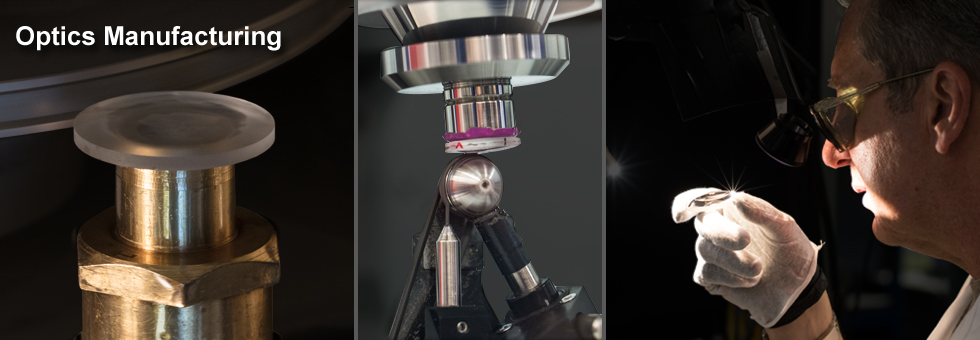
Precisionoptics manufacturing
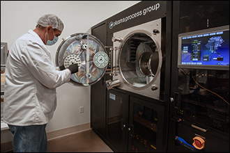
Cleanliness and surface quality of uncoated optics are paramount for ensuring performance, especially in high-power laser applications. Optics to be coated are delivered from fabrication to the coating lab, which maintains an ISO Class 10,000 Cleanroom status. The optics are then put through a four-bath ultrasonic cleaning machine. This process uses a combination of detergents and micro-cavitations to free contaminants from the surface of the optics. Each optic is then inspected and spot cleaned by hand. Parts that pass inspection are loaded into a coating chamber.Our coating lab has a number of vacuum chambers rigorously monitored and maintained by our technicians. Each chamber utilizes different deposition techniques tailored for the coating they are used to produce. Deposition techniques include resistive heat evaporation, electron beam evaporation with ion-assisted deposition, and ion beam sputtering. Our chambers control, monitor, and record process parameters, though technicians still manually override these programs to make adjustments to the process on the fly. To see the processes we use in more detail, along with our standard thin film coatings, see our Optical Coatings page.
Once an optic has passed all of its inspection points, it can be used in one of two ways: the optic can be packaged and sold as an individual item, or it can be incorporated into an assembly. Our packaging goes through drop testing to help prevent damage from accidental mishandling when an optic is inside. In addition, optics can be vacuum packaged to prevent any environmental contamination during transit to your site. Our assemblies can be as simple as mounting the optic for easy integration into an experimental setup, or as complex as a multi-element telescope, collimator, or microscope objective. Thorlabs’ vertically integrated structure allows us to utilize our own machine shops to provide custom mounting for optics, along with assemblies built to form fit OEM applications.
Optics manufacturingprocess pdf
The USB3AUB50CMB SuperSpeed USB 3.0 Micro B cable provides a high quality connection to your Micro USB-equipped USB 3.0 devices.
Spherical and Aspherical LensesSpherical and aspherical optics can be ground down from plano-plano round blanks which are made in house (described previously in the Plano Fabrication tab). CNC Satisloh machines grind and polish the glass rounds to shape, making lenses between 10 mm (0.39") and 140 mm (5.5") in diameter. These machines have software that integrates with our Zygo metrology stations, making in-process adjustments to lenses streamlined and accurate. The processes are closely monitored by our opticians, who maintain the machines and ensure the parts being produced meet our standards.
Opticalmanufacturingjobs
Metal SubstratesOur diamond point turning machines can cut and finish curved optics from materials that cannot easily be accommodated in the Satisloh machines, such as our off-axis parabolic mirrors, conic mirrors, and lenses for the mid- to deep-IR. Blanks for the mirrors are machined in Thorlabs' mechanics department. The roughly shaped lens substrates or mirror blanks are mounted on a circular tool that can spin at up to 10,000 rpm. As the tool rotates, a diamond cutting tool is pressed against the blanks to shave away material, creating the desired shape and surface quality. Combined with our other machining capabilites, exotic form factors can be created, like the one shown in the image to the right.
Optical Lensmanufacturingmachine
Many double-side polished parts leave shaping and proceed to Speedfam polishing machines, which sandwich hundreds of parts between proprietary grinding pads and slurry. Grinding pads need to be designed very carefully in order to move polishing compound and debris to and from the optics’ surfaces without scratching or unevenly polishing them. These machines also achieve a surface roughness of 3 to 5 Å on both sides of an optic, while retaining a parallelism as low as 5 arcsec. Quality Control After the polishing process is complete, the optics are removed from reference blocks, cleaned, and brought to in-process quality control for inspection. Surface quality tolerances vary from product to product, and can be made tighter or looser for custom parts upon customer request. When optics meet the needed specifications, they can be sent to a number of destinations. For some plano optics, this is the end of the line and they are packaged and sold as finished products, or assembled into other Thorlabs assemblies (see the Final Inspection tab). Others are sent to our coating lab to receive one of our optical thin film coatings (see the Coating Lab tab). But for some, this is only the beginning, as they are sent to be ground and polished into lenses (see the Lens Fabrication tab).
Once the specifications are mutually agreed upon, our engineers will use tools such as AutoCAD, Zemax, and TFCalc to draft the optic or optical system. The finalized design will be used to create internal manufacturing drawings, which are the basis for the quote provided by your assigned Technical Administrator or Sales Coordinator.Our optics facilities are staffed by well-trained, experienced technicians and engineers. Together, they combine years of experience with advanced machinery and tightly toleranced metrology to transform raw materials into finished optics. To learn more about our step-by-step fabrication capabilities, click on the images below or click through the tabs above.
Les produits disponibles sur notre site web ne sont pas nécessairement en magasin. Notre site web reflète également l'inventaire de nos entrepôts, sur commande.
Polishing Once shaped, optics are polished one surface at a time using traditional block-and-polishing. In this process, parts are temporarily adhered, or blocked, by hand to a reference plate using either wax, resin, or, where high parallelism is needed, optical contacting. These methods protect the back surface of the optics while making sure they do not move during the polishing process. The blocked parts are then ground using Strasbaugh spindle polishers, which are constantly monitored and adjusted by our technicians through in-process measurements using interferometers. With this method, experienced technicians are able to regularly achieve a wavefront error of less than λ/10 and surface roughness between 3 to 5 Å. Special block-and-polish stations that grind extremely slowly and precisely allow us to reach flatness near λ/40 and surface roughness as low as 1 Å on some optics; often these machines are used to resurface the reference plates used earlier in the process.
For more details about the coating process and coatings we offer, see our Optical Coatings Tutorial. We also have a tutorial on our Optical Substrates.
We offer a single point of contact to work with you through the design process of a custom or OEM order. This contact will discuss the scope of your design and application including, but not limited to, substrate materials, dimensions, and optical coatings. We are capable of measuring multiple angles of incidence, in- and out-of-band performance on optical coating witness samples, verifying surface quality and physical dimensions, providing custom packaging, and performing compliance testing (see our Final Inspection tab for details). We request that any measurement data, other reports, or custom packaging needs are mentioned as early in the request process as possible. For OEM orders, we can provide production planning services such as Kanban and blanket ordering.
The Thin Film Coating Laboratory at Thorlabs houses a plethora of vacuum chambers and spectrophotometers that aid in the creation of thin film optical coatings. A team of experienced engineers and technicians design, deposit, and measure thin film coatings ranging from our standard anti-reflective coatings to exotic mirror coatings. The process starts by modeling the coating necessary to meet catalog specifications or previously discussed customer tolerances using software packages like OptiLayer and TFCalc. Carefully controlled test runs are performed to ensure a stable and consistent production process. Once design and testing yields a repeatable process, production can begin.
EdmundOptics
Optics manufacturingcompanies
The short 0.5m /1.5-foot cable length is perfect for close-range connections (e.g. connecting a portable hard drive to your laptop) and the lightweight, compact design fits nicely into any carrying case.
Leveraging this infrastructure, Thorlabs offers custom and Original Equipment Manufacturing (OEM) ordering for optics and optical assemblies to bring a wide range of options and features to you. OEM orders are components or assemblies that will be used towards finished goods, manufacturing tools, or pieces of testing equipment. For OEM inquiries, please contact techsales@thorlabs.com. If your request for a component or assembly is for a small research project, hobbyist endeavor, or if you’re not sure if your request falls into the listed OEM categories, contact Tech Support at techsupport@thorlabs.com or by phone at (973) 300-3000. For regional Tech Support, see our Support Contact Information page.
Optical lensmanufacturingprocess PDF
In 1989, Thorlabs’ founder, Alex Cable, began building optomechanical components in his garage using a single upright milling machine. His goal was to provide essential laboratory equipment at an affordable price with fast, direct customer service. Today, Thorlabs is known for manufacturing an extensive catalog of products for the photonics industry while retaining those core principles. As we have grown into a global enterprise, our infrastructure has remained focused on being a design-to-delivery manufacturer.
The USB3AUB50CMB SuperSpeed USB 3.0 Micro B cable provides a high quality connection to your Micro USB-equipped USB 3.0 devices. The short 0.5m /1.5-foot cable length is perfect for close-range connections (e.g. connecting a portable hard drive to your laptop) and the lightweight, compact design fits nicely into any carrying case. This Micro USB 3.0 cable is backed by StarTech.com’s Lifetime warranty for guaranteed reliability. Applications Connecting Micro USB 3.0 devices (portable hard drive, card reader, video capture device, hard drive enclosure, etc.) to a USB 3.0 compatible PC or laptop Specifications Warranty Information Warranty Lifetime Connector(s) 1 - Connector A USB Type-A (9 pin, 5 Gbps) 1 - Connector B USB 3.0 Micro-B (10 pin, SuperSpeed) Hardware Connector Plating Nickel Cable Jacket Material PVC - Polyvinyl Chloride Cable Shield Material Aluminum-Mylar Foil with Braid Packaging Information Package Height 0.3 in [7.0 mm] Package Length 8.7 in [22.0 cm] Shipping (Package) Weight 1.3 oz [38.0 g] Package Width 7.9 in [20.0 cm] Package Quantity 1 Performance Type and Rate USB 3.0 - 5 Gbit/s Physical Characteristics Weight of Product 1.1 oz [31.0 g] Color Black Connector Style Straight Wire Gauge 28 AWG Cable Length 1.6 ft [0.5 m] Product Length 1.6 ft [0.5 m] Product Width 0.6 in [16.0 mm] Product Height 0.3 in [0.8 cm] What's in the Box 1 - Included in Package 0.5m Black SuperSpeed USB 3.0 Cable A to Micro B - M/M
After deposition, coated optics go through another round of hand inspections and witness samples are optically profiled with Varian spectrophotometers. The measurements taken at this step are to that ensure optical performance meets specifications. Many optics will go through a second round of coating for an anti-reflective coating to their back sides before moving on to final inspection (see the Final Inspection tab).
Once a lens has been given the correct curvature, it must be centered. We utilize Satisloh centration machines to ensure axis centering down to 5 arcseconds, accommodating the <3 arcminutes specification we have for most of our optics. While these centration machines are mainly used to grind down the edge of an optic to meet our diameter and centration specifications, we have also used them to produce custom-shaped optics for customers and other groups within the organization.
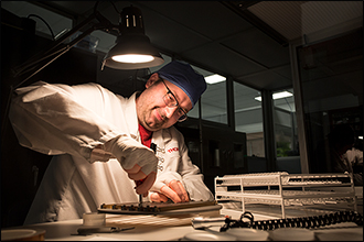
Quality Control is a constant part of the fabrication of optical elements at Thorlabs. Each step of the process has its own checkpoints where our quality control technicians meticulously inspect the optics for both surface quality and incremental performance improvement. In order to guarantee that every component we deliver meets our mutually agreed upon specifications, each optic is put through a final inspection. Final inspection of our optics generally includes measuring the optical element’s physical properties, optical performance, and environmental fortitude. As stated in the Design and Engineering tab, if a customer has requested special measurements, records of standard measurements, or other services, this is the step in the process at which those services will be realized.Physical parameters tested include diameter, center thickness, surface flatness, parallelism, and surface quality. Surface quality is measured to MIL-PRF-13830B specifications. This United States military standard calls for a visual inspection performed against a black background with a 40 W light bulb; we exceed this inspection standard in some cases by using high-power fiber-lights, as seen in the photo to the right.Optical performance, inlcuding wavefront error, focal length, and coating performance, is evaluated. Wavefront error can be resolved down to the sub-angstrom level. Transmission and reflectance data can be captured between 200 nm to 55.5 µm.Environmental testing can include laser damage threshold of the optical element, thermal cycling, humidity cycling, and coating durability/adhesion.
Optics manufacturingnear me
At Thorlabs, we use vertically integrated processes to turn raw materials and refined bulk glasses into high-quality plano optics. These processes incorporate both automated machines and skilled craftsmen, providing a diverse catalog of standard plano optics and the flexibility to create specialized optics tailored to a customer’s needs.
Shaping To begin rough shaping the glass, we have a multitude of dicing saws and coring drills. With this battery of machines, we can create plano optics from Calcite, N-BK7, Fused Silica, SF11, and NG Series Schott, among other materials (for a complete list of our substrates, see our Optical Substrates tutorial). Plano optics up to 10" in diameter or 7" x 7" square can be created in a diverse range of shapes and sizes. Most circular optics receive chamfers from an automated edger, which quickly and accurately creates a protective edge that prevents fractures and chips to the optic. For irregularly shaped optics, skilled opticians create a chamfer by hand using polishing wheels.
Diffraction-Limited ApsheresTo create diffraction-limited aspheric lenses, QED Technologies Magnetorheological Finishing (MRF) Polishers are used. Instead of the solid bits and disks used in our Satisloh machines, these machines refine the polish created by the Satisloh machines by running a ferrofluid infused with polishing compound along the lens. This dynamic process can bring a lens’ surface accuracy within 55 nm, depending on the material being polished. Removal of manufacturing defects to this degree enables a very low wavefront error. Just like our other polishing machines, this MRF polisher communicates with our metrology to provide fast and accurate adjustments.


 Ms.Cici
 8618319014500