
6-Pin Mini-DIN “Packet”/”Data” Connector - 6 pin connector din
Note: These cables are not designed to provide any temperature regulation. More information on temperature regulating a laser diode is provided in the Laser Diode Tutorial.
Learning how to understand and control depth of field in your photographs is one of the best ways to take your photography to a new level. And it’s not difficult! So what is it, and how do we use it?
Collimation radiology
Laser Diode Temperature WarningPlease note that these collimation tubes do not have any temperature regulation or temperature measurement capability, so we do not recommend using them with higher power laser diodes without additional thermal regulation. Running a laser diode at a high operating temperature can significantly shorten its lifetime.
Each model corresponds to one or more of the standard Pin Styles for laser diodes (see the diagram below) and is compatible with our Laser Diode Collimation and Focusing Tubes, Ø1/2" Post Mounts, and Cage Plate Mounts. SR9 models are designed for laser diodes with forward voltages up to 3.3 V, while SR9H models are designed for laser diodes with forward voltages up to 7.5 V. Each strain relief is available with or without a DB9 connector. Models with item #'s that end in -DB9 are pin compatible with many of our Laser Diode Controllers (see the strain relief cable and controller pin diagrams to determine compatibility).
How to make acollimatedbeam
The term depth of field is defined by Wikipedia as “the distance between the nearest and farthest objects in a scene that appear acceptably sharp in an image.” So in a photograph with a large depth of field, most of the objects in both foreground and background will appear sharp. In a photo with a shallow depth of field, the object that the photographer focuses on will appear sharp, while areas in front of or behind it may appear soft and out of focus.
Then in any given situation, you can evaluate the scene in front of you, and decide whether you would like front to back sharpness or not. You might choose to use a shallow depth of field in order to emphasise just part of the scene by throwing other areas out of focus. Typical examples of this might be isolating a flower and throwing its distracting background out of focus, or taking a portrait of a person against a background which doesn’t add anything to the image when it is sharp.
Laser Diode Temperature WarningPlease note that these collimation tubes do not have any temperature regulation or temperature measurement capability, so we do not recommend using them with higher power laser diodes without additional thermal regulation. Running a laser diode at a high operating temperature can significantly shorten its lifetime.
The exact depth of field in any situation will also depend on the distance between yourself and the subject that you are photographing. And this is also related to another factor – the type of lens that you use.
Collimatedbeam meaning
Collimated lightvs polarized
In other situations you may want front to back sharpness in your photograph, perhaps in landscape or architectural photography.
If this is getting a little too complicated, then just go back to the golden rule - the higher the f stop number, the larger the depth of field!
These strain relief and ESD protection products offer a convenient means of connecting a Ø5.6 mm or Ø9 mm laser diode to many of Thorlabs' laser diode controllers. Each model comes with a laser socket mounted to a small-printed circuit board (PCB). The PCB contains a Schottky diode to clamp any reverse voltages that might appear across the laser diode, as well as a Zener diode to shunt any excessive voltages or ESD away from the diode.
Example: S-Curve with Rising EdgeThe angle (θ = ftr ) subtended by the beam depends on the signal's rise time (Figure 3) and the wheel's rotation rate (f ), whose units are Hz or revolutions/s. The arc length (Rθ = R ⋅ ftr ) through the beam can be calculated using this angle. For a small Gaussian-shaped beam (Figure 4), a first approximation of the 1/e2 beam diameter (D ),
Other Wavelength Ranges and Collimation OpticsThe Laser Diode Collimation Tube is shipped with the aspheric lens (collimation optic) premounted. However, a different aspheric lens can be substituted for better performance at different wavelengths. Any of our M9 x 0.5 threaded mounted aspheric lenses are compatible with the LT110P-B, LT220P-B, and LT230P-B collimation tubes, while any of our M12 x 0.5-threaded mounted aspheric lenses are compatible with the LT240P-B collimation tube. The SPW301 or SPW302 spanner wrenches, respectively, can be used to remove and install these two sizes of aspheric lenses. Please contact Tech Support if you would like to purchase the collimation tube without the aspheric lens, or with a different lens.
Collimatedflashlight
But there are no rules about this, and the decision about depth of field is one of the creative choices open to the photographer – and one which will significantly affect the resulting photograph.
The SPW301 spanner wrench can be used to install any of our Ø5.6 mm or Ø9 mm laser diodes in the collimation tube. A Ø9 mm laser diode can be directly installed into the tube with the included retaining ring, while a Ø5.6 mm laser diode can be installed with the use of the included adapter kit.
However, if you were to move closer to the tree and photograph it with the 28mm lens in such a way that the size of the tree in the resulting image was the same as in the image taken with the 300mm lens, then at the same aperture setting, the depth of field given by each lens would be the same as well.
Collimating lens
Figure 2: The blade traces an arc length of Rθ through the center of the beam and has an angular rotation rate of f. The chopper wheel shown is MC1F2.
If you photograph the same subject from the same place with different lenses, a telephoto lens will give you a shallower depth of field than a wide angle lens. For instance, if you focus on a tree with a 300mm lens, you will have a much shallower depth of field than you would if you photographed the same tree from the same position with a 28mm lens, at the same f/stop setting.
Collimatedvs coherent
Mounting OptionsThorlabs' Adjustable Laser Diode Collimation Tubes can be secured in a KM100 Kinematic Mount using the AD15NT adapter. Alternatively, they can be mounted in an SM1-threaded mount using our AD15F adapter, as illustrated in the video at the top of the page. However, the outer diameter of the external locking ring on these collimation tubes will not fit in these adapters. As such, the tubes can only be placed into the adapter in one direction, and they will not pass all the way through the adapter. Therefore, the laser diode socket should be passed through the adapter before connection to the diode in the collimation tube. Alternatively, the locking ring can be removed by first removing the tube's end cap. As an alternative mounting option, these collimation tubes can be secured in a KM100V kinematic V-mount.
Thorlabs' Adjustable Laser Diode Collimation Tubes are shipped with an aspheric lens (collimation optic) premounted. The position of this lens can be adjusted by up to 2.5 mm (0.1") by rotating the cap on the end of the tube. The position of the lens can then be locked using the external locking ring. Rotation of the cap by 5° corresponds to a linear displacement of the lens by 5.5 µm, and an engraved scale on the actuating cap allows for accurate lens positioning. The lens translates inside the tube without rotation for enhanced pointing stability. The large travel range of the optic ensures that these collimation tubes can be used to collimate any of Thorlabs' laser diodes that emit within their AR coating range. However, the lens in these collimation tubes is not meant to be replaced.
Figure 1: An approximate measurement of beam size can be found using the illustrated setup. As the blade of the chopper wheel passes through the beam, an S-curve is traced out on the oscilloscope.
To make this beam size measurement, the combined response of the detector and oscilloscope should be much faster than the signal's rate of change.
A chopper wheel, photodetector, and oscilloscope can provide an approximate measurement of the beam size (Figure 1). As the rotating chopper wheel's blade passes through the beam, an S-shaped trace is displayed on the oscilloscope.
includes a factor of 1.56, which accounts for the portion of the beam measured between the 10% and 90% intensity points being smaller than the 1/e2 beam diameter.
Collimate telescope
Laser Diode Temperature WarningPlease note that these collimation tubes do not have any temperature regulation or temperature measurement capability, so we do not recommend using them with higher power laser diodes without additional thermal regulation. Running a laser diode at a high operating temperature can significantly shorten its lifetime.
Figure 3: Rise time (tr ) of the intensity signal is typically measured between the 10% and 90% points on the curve. The rise time depends on the wheel's rotation rate and the beam diameter.
When the blade sweeps through the angle θ , the rise or fall time of the S-curve is proportional to the size of the beam along the direction of the blade's travel (Figure 2). A point on the blade located a distance R from the center of the wheel sweeps through an arc length (Rθ ) that is approximately equal to the size of the beam along this direction.
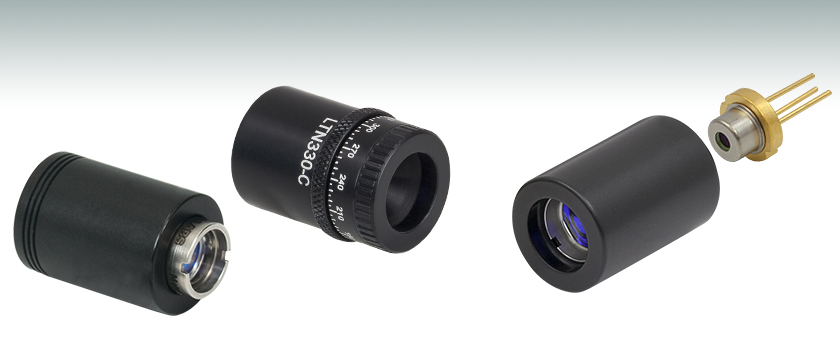
These laser diode focusing packages are similar to our laser diode collimation packages sold above but include an aspheric lens pair for focusing of the laser diode output. The focus can be adjusted by threading the mounted lens pair in or out. These packages are compatible with our SR9 laser diode sockets, available below.
Thorlabs offers passive laser diode mounts with premounted aspheric optics for collimation or focusing applications. Each of these mounts is compatible with our strain relief and ESD protection cables, also offered below. These mounts are compatible with low-power Ø5.6 mm or Ø9 mm laser diode packages and do not offer active cooling. They can be adapted to standard Ø1" mounts such KM100 Kinematic Mount using the AD15NT Adapter. They can also be mounted in SM1-threaded lens tubes and optomechanics using the AD15F or AD15F2 Adapters.
The amount of depth of field is controlled by setting the aperture in your camera’s lens (The hole size). The aperture settings are known as f stops, and are represented by a range of numbers from around f/2.8 to around f/32. The exact range will vary from one lens to another.
Camera and scanning-slit beam profilers are tools for characterizing beam size and shape, but these instruments cannot provide an accurate measurement if the beam size is too small or the wavelength is outside of the operating range.
The lower numbers (f/2.8 etc.) will give you a wide aperture (a large hole), while the higher numbers give you a small aperture.


 Ms.Cici
 8618319014500