
1.4: Microscopy - Biology LibreTexts - microscope high power objective lens
Previous studies have shown that image quality has improved using tight collimation. 4 Larger collimation areas increase the amount of scatter produced, and this is particularly important on thicker body parts, such as the HBL hip. Scatter negatively impacts subject contrast 5 and spatial resolution. 6 Previous studies have demonstrated collimation can greatly reduce radiation dose and associated risks. 7
All of the states of polarization described above are actually special cases of the most general state of polarization, called elliptical polarization, in which the tip of the electric field vector E traces out an ellipse in the x-y plane. The two components might have unequal amplitudes Ax Ay , and also might contain a different relative phase, often denoted That is, we may write generally
A previous survey of 493 radiologic technologists found nearly half (48.9%) of respondents used electronic collimation more than 75% of the time. 9 Whilst this study did not compare the EFOV to the FOV sent to PACS, removal of the electronic cropping to calculate the measurements in our study indicates that electronic cropping is a routine practice. A study by Tsalafoutas found that electronic cropping was the norm and not the exception. 10 Electronic cropping can result in pathology being missed 3 and does not replace the importance of collimation of the primary x‐ray beam for reducing patient dose and improving image quality. 2 This inlays the issue of anatomy exposed to radiation that is not being assessed by a clinician on completion of examination.
Unpolarized light can be polarized using a “polarizer” or “polarizing beamsplitter,” and the state of already polarized light can be altered using a polarizer and/or optical components that are “birefringent.” In this section we explore some examples of these types of components.
A retrospective clinical audit of five common musculoskeletal radiographic projections (AP knee, AP shoulder, horizontal beam lateral hip, lateral cervical spine and lateral facial bones), of 359 patients was undertaken. The electronic cropping was removed from projections, and the superior–inferior, antero‐posterior and medio‐lateral collimation size was measured, depending on the projection. The two measurements were multiplied to give an exposed field of view area. The three measurements were compared with a reference standard, being the size of the corresponding cassette size used in the department on film/screen or computed radiography.
Polarizationofelectromagnetic waves pdf
Suppose the two components have equal amplitudes again, but now consider the case where these two components are not in phase, such that the angles of the sine functions are different. In particular, suppose there is a constant phase difference of p/2 between them, which corresponds to a distance of l/4 in the “fixed time” picture. The x component is
We can see that in general the light emerges in a different state of elliptic polarization. In fact, for the example illustrated above, the particular choice of L for a given difference between nx and ny causes the linearly polarized light at the input end to be converted to circularly polarized light at the other end of the birefringent material. How did this happen? Let’s look at the math. Consider the phases accumulated by the two component waves as they travel through the birefringent material. The waves can be described by
From the five projections, 1071 measurements were analysed. 416 (38.8%) of these measurements were less than or equal to the agreed reference standard. 655 (61.2%) were greater than the agreed reference standard.
Correspondence , Sally Ball, Department of Medical Imaging, Princess Alexandra Hospital, Brisbane, Australia. Tel: +61 07 31762971; E‐mail: sally.ball@health.qld.gov.au
The amplitude E, or the potential for a charged particle to feel a force, is vibrating along both the x and y directions. An actual charged particle would feel both of these fields simultaneously, or it would feel
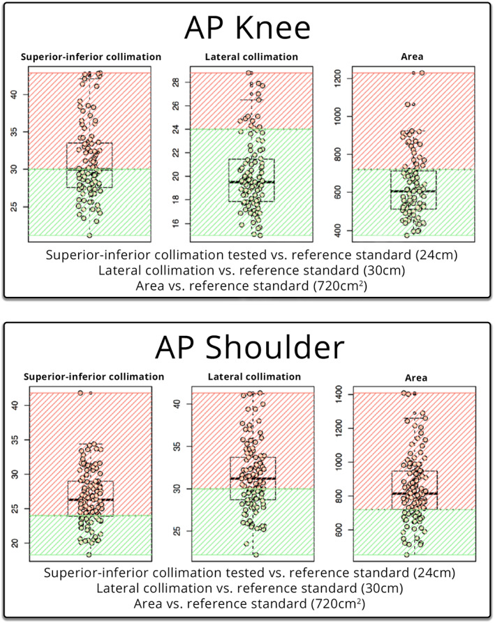
When measured against the reference standard, supero‐inferior collimation was lower or equal to the limit in a total of fifty patients (50.51%), whilst forty‐nine patients (49.49%) were above the limit (Table 1). The lateral collimation was lower or equal to the limit in a total of eighty‐six patients (86.87%), whilst thirteen patients (13.13%) were above the limit. The EFOV was lower or equal to the limit in a total of seventy‐six (76) patients (76.77%), whilst twenty‐three patients (23.23%) were above the limit.
That is, E appears to oscillate along a line oriented at 45° with respect to the x axis. Hence this situation is called linear polarization.Notice that equivalently we could view the wave at a particular location (“fixed position”) and watch its amplitude evolve with time. Suppose we sit at the position z = 0. Then we see that
Collimation is the limitation of the primary x‐ray beam by blade‐type diaphragms on the x‐ray tube. Collimation of the primary beam to the area of interest limits the radiation dose to the patient by limiting the amount of tissue that is exposed. Appropriate collimation has always been an important factor in image quality, as it reduces the amount of scatter produced, which increases image quality.
In other words, if we look down the propagation axis in the positive x direction, the vector E at various locations (and at t = 0) now looks like:
VD Tang · 2023 — Focal length is the distance between the lens and the focal point, where the light rays converge or diverge.
A total of one thousand and seventy‐one measurements were recorded. Four hundred sixteen measurements (38.8%) measured at or below the reference standard. Six hundred fifty‐five measurements (61.2%) measured above the reference standard. The results are available in Table 1.
What if the two components Ex and Ey have unequal amplitude factors? We can see that the light wave is still linearly polarized.
What is polarizationofwaves in Physics
It is also possible to take advantage of an appreciable difference in reflected or transmitted phase for p- and s-polarized light over a region of the spectrum where the reflected and transmitted intensities are essentially equal, thus forming a waveplate.
The authors would like to thank and acknowledge Justin Scott, Biostatician from the Metro South Biostatistics Clinic, Queensland Cyber Infrastructure Foundation Bioinformatics, Institute for Molecular Bioscience, The University of Queensland, Australia for his clear guidance, and Anne Bernard, Head of Biostatics, Queensland Cyber Infrastructure Foundation Facility for Advanced Bioinformatics, for providing the original statistical analysis.
The reference standard was the corresponding cassette size used for the individual projection in film/screen or computed radiography (CR). The cassette size was chosen as the reference standard as it represents the largest collimated field required to demonstrate the anatomy in the projection. The null hypothesis was that the collimation was not greater than the maximum cassette size. The body parts were chosen to represent the axial and appendicular skeleton, with a variety of AP and lateral projections, that would traditionally have been taken on different cassette sizes.
Using this description of a single transverse orientation of a light wave, we can now consider multiple orientations to describe different states of polarization.
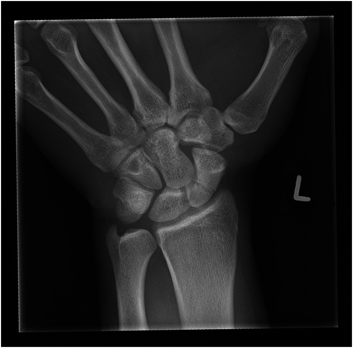
Wrist radiograph with collimation margins visible creating a white or ‘silver’ border around the image indicating the image is the entire exposed field of view with no digital cropping.
Thirty‐two examinations were assessed against the reference standard (24 cm x 18 cm = 432 cm2), the summary description can be seen in Table 1. Two examinations had incomplete data and were omitted from the analysis. The visualisation of the data is presented in Figure 2 against the reference standard (in green).
To understand the polarization of light, we must first recognize that light can be described as a classical wave. The most basic parameters that describe any wave are the amplitude and the wavelength. For example, the amplitude of a wave represents the longitudinal displacement of air molecules for a sound wave traveling through the air, or the transverse displacement of a string or water molecules for a wave on a guitar string or on the surface of a pond, respectively. We will refer to the amplitude of a light wave with the letter “E.” The amplitude of a light wave represents the potential for a charged particle (such as an electron) to feel a force – formally it may represent the “electric field” of an electromagnetic wave. Because this potential vibrates along the directions transverse to the direction the wave is traveling, light is a “transverse wave,” just like the waves on a string or water surface.Because light is a transverse wave, and because there are two transverse dimensions, there are fundamentally two distinct directions in which the light wave may oscillate. Let’s call these the x and y directions for a light wave traveling along the z direction. We’ll call the two distinct waves Ex and Ey, where we denote these by vectors to remind us that they point in (or oscillate along) a certain direction (the x and y directions, respectively).The amplitude of the light wave describes how the wave propagates in position and time. Mathematically, we can write it as a “sine wave” where the angle of the sine function is a linear combination of both position and time terms:
Seventy‐three examinations were assessed against the reference standard (30 cm x 24 cm = 720 cm2), the summary description can be seen in Table 1. The visualisation of the data is presented in Figure 2 against the reference standard (in green).
Two radiographers, one with seventeen years' experience and the other with three years' experience, carried out the data collection. The more experienced radiographer had worked on film screen, CR and DR, while the junior radiographer had worked predominantly on DR. For the analysis, any electronic cropping of the image was removed, and the EFOV was assessed. The horizontal and vertical measurements of the primary x‐ray beam were recorded. This was the supero‐inferior, medio‐lateral or antero‐posterior collimation dependent upon the whether the antero‐posterior (AP) or lateral view was being reviewed. The two measurements were then multiplied to calculate the EFOV area. These three measurements were then compared with an agreed upon reference standard.
Polarizationof lightnotes PDF
With your consent, we may also use non-essential cookies to improve user experience and analyze website traffic. By clicking Accept, you agree to our ...
The laser pointer game for dogs! Everyone loves a dog chasing a laser pointer, right? Laser Point for Dogs will pick random paths on your phone screen that ...
If the difference between the two phase values is p/2, then the wave emerging from the material (say into air) will be circularly polarized. This occurs when
Our motorized linear stages are made by high precision guide and lead screw. We can provide all kinds of assembly of linear stages, including xy stage, ...
Proper collimation will only yield accurate results when radiographic position is performed correctly, and the beam correctly centred over the appropriate anatomy. A correctly collimated HBL should present the acetabulum, and the head and neck of femur, with the centring point midway between the anterior and posterior margins. The top image in Figure 3 demonstrates the effect of poor collimation practices. Image A of Figure 3 demonstrates an HBL hip with a measured dimension of 23 × 40 cm, measuring an EFOV of 920 cm2, 213% of the appropriate cassette size. The centring point is over the upper third of the femur. The result is a lack of detail over the femoral head and neck, and the image contrast is poor. The image was repeated minutes later (image B) utilising the same exposure factors, the EFOV is 432 cm2, collimated to the dimensions of the appropriate cassette size (18 × 24 cm). The opposite leg was also further abducted which reduced the soft tissue artefact overlying the neck of femur (NOF). There is a significant difference between the two images, with the repeated image demonstrating better detail of the femoral head and neck and improved image contrast. The centring point is also demonstrated to be over the NOF.
However, if the optical system is in any way sensitive to polarization, even when the incident light is unpolarized, it is important to recognize that the beamsplitter can transmit and reflect different amounts of the “s” and “p” polarization states, as shown below.
Official websites use .gov A .gov website belongs to an official government organization in the United States.
FOV stands for Field of View, which is the width of the observable area that can be seen through an optical device, such as binoculars or a monocular.
When measured against the reference standard, antero‐posterior collimation was lower or equal to the limit in a total of six patients (14.29%), whilst thirty‐six patients (85.71%) were above the limit (Table 1). The supero‐inferior collimation was lower or equal to the limit in a total of zero patients (0%), whilst forty‐two patients (100%) were above the limit. The EFOV was lower or equal to the limit in one patient (2.38%), whilst forty‐one patients (97.62%) were above the limit.
Collimation of the primary beam is an important factor in radiography to reduce dose and improve image quality. The introduction of larger detector plates in direct digital radiography (DR) allows the exposed area to be calculated by removing cropping applied to the image. The aim of this study was to assess whether the exposed area was larger than a reference standard across five different projections on different body types, with the reference size being the corresponding cassette size used in traditional film/screen or computed radiography (CR).
On a digital image, lack of collimation has a detrimental effect on image quality, increasing the amount of scatter hitting the digital detector. The increase in scatter can be a contributing factor to the histogram widening, resulting in a greyer image and a decreased spatial resolution, resulting in a lack of detail of the anatomy visualised. 2
When an optical filter is used at a non-normal angle of incidence, as is common with so-called “plate beamsplitters,” the filter can impact the polarization of the light. If the incident light is incoherent and unpolarized, and the optical system is “blind” to polarization, the standard intensity reflection and transmission functions R(l) and T(l) may be determined for the new angle of incidence, and they are sufficient to characterize the two emerging beams.
While pre‐set collimation field sizes are built into the machines, individual users can adjust the irradiated area manually. Collimation of the primary x‐ray beam remains the best practice for limiting the radiation field to comply with as low as reasonably achievable (ALARA) principles. 2
where A is called the “amplitude factor,” the variable l (“lambda”) is the “wavelength” (units of nm), and the variable v (“nu”) is the “frequency” (units of Hz, or sec–1). If a snapshot of the wave could be taken at a fixed time, l would be the distance from one wave peak to the next. If one sits at a fixed point in space and counts the wave peaks as they pass by, v gives the frequency of these counts, or 1/v gives the time between peaks. The sign between the position and time terms determines the direction the wave travels: when the two terms have the opposite sign (i.e., the “–” sign is chosen), the wave travels in the positive z direction. For convenience we often use two new variables called the “wavenumber” k = 2p/l and the “angular frequency” 2pv (“omega”), which absorb the factor of 2p, so that the wave amplitude can now be written more compactly as
The AP knee projection was the only projection that had the majority of the measurements below the reference standard. This may be due to the anatomy and positioning involved, where the lateral skin margins of the knee are easily visible while undertaking collimation.
Get Quote ... Holmarc's CCD Based Laser Raman Spectrometer apparatus (Model No: HO-ED-S-06A) is an apparatus designed for recording Raman spectra of both solids ...
Because of this relationship, a material with birefringence Dn of the appropriate thickness L to convert linear polarization to circular polarization is called a quarter-wave plate.What causes materials to be birefringent? Some materials, especially crystals, are naturally anisotropic at microscopic (sub-wavelength) size scales. For example, Calcite (CaCO3) is shown in the drawing below. The structure, and hence the response to polarized light, along the c direction is markedly different than that along the a and b directions, thus leading to a different index of refraction for light polarized along this direction.
Polarisation of lightin physics
When radiographs were performed on film, every aspect of the imaged anatomy was visible. With the advent of electronic cropping, increased workload, combined with larger DR plates, contemporary radiography risks an environment in which patient throughput begins to take priority over image quality. DR post‐processing capabilities enable the user to electronically crop, or mask, to a smaller field of view (FOV) to only include the relevant anatomy in question, which results in an increased dose to the patient with no added benefit. Anatomy in the exposed field of view (EFOV) can be cropped electronically and therefore not available to the interpreting medical professional. 3
The angle of the reflected ray,θr, is always equal to the angle of the incident ray, θi, this result is called the “law of reflection.” The angle of the transmitted (or refracted) ray, θT, is related to the angle of incidence by the well-known “Snell’s Law” relationship: ni sin θinbsp;= nt sin θT. It turns out that s-polarized light is always more highly reflected than p-polarized light. In fact, at a special angle called “Brewster’s Angle,” denoted θB, the p-polarized component sees no reflection, or is completely transmitted. Brewster’s angle is given by θB = arctan(nt/ni). The power or intensity reflection coefficients for a light wave (i.e., the squares of the amplitude reflection coefficients) for air-to-glass (left) and glass-to-air (right) look like:
Polarization examples
Other materials are nominally isotropic, but when they are bent or deformed in some way, they become anisotropic and therefore exhibit birefringence. This effect is widely used to study the mechanical properties of materials with optics.
Some materials have a different index of refraction for light polarized along different directions. This phenomenon is called birefringence. For example, suppose light polarized along the x direction sees an index of nx, while light polarized along the y direction sees an index ny. Now suppose linearly polarized light passes through a piece of such a material of length L, where the linear polarization axis is oriented at 45° with respect to the x and y axes. The fixed time picture thus looks like:
The study also did not assess the difference between the EFOV and the area of the FOV sent to PACS. Future studies could incorporate a greater range of projections to increase the amount of data available for analysis.
This is an open access article under the terms of the http://creativecommons.org/licenses/by-nc-nd/4.0/ License, which permits use and distribution in any medium, provided the original work is properly cited, the use is non‐commercial and no modifications or adaptations are made.
They are commonly used for enclosures, walls, glove boxes and windows. Acrylic & Glass Configurations: Phillips stocks standard sizes of 12 12, 24 x 24, and 24 ...
If Ax Ay , the total wave E is linearly polarized, but it is no longer oriented at 45° with respect to the x axis. In fact we can see that it is oriented at an angle where
This study found that of the fifteen measurements taken, twelve measurements were more than 50% above the reference standard. This indicates that collimation is being undertaken poorly on a range of examinations. All three measurements for the HBL hip and lateral facial bones had more than 80% of the measurements greater than the reference standard.
This retrospective audit was undertaken at a large, metropolitan tertiary hospital. The hospital does not provide paediatric services, so all patients in the study were over the age of sixteen. The investigation was retrospective in design and granted exemption from ethical review by the Metro South Human Research Ethics Committee. No identifying data or patient demographics were collected, so no written informed consent was required. Patient information was removed and entered into Microsoft Excel™ for analysis.
When measured against the reference standard, supero‐inferior collimation was lower or equal to the limit seventeen patients (23.29%), whilst fifty‐six patients (76.71%) were above the limit. The antero‐posterior collimation was lower or equal to the limit in a total of thirty‐six patients (49.32%), whilst thirty‐seven patients (50.68%) were above the limit. The EFOV was lower or equal to the limit in thirty‐two patients (43.84%), whilst forty‐one patients (56.16%) were above the limit.
When the electric field of a light wave encounters the sheet, the component parallel to the chains causes electrons to oscillate along the direction of that component (Ey in the above example), thus absorbing energy and inhibiting the component from passing through the sheet. Because electrons can not respond to the other component (Ex), it is readily transmitted.
Initially, it was hypothesised that the larger collimation field sizes demonstrated in this study was the result of ‘collimation creep’, whereby the use of electronic cropping was an avenue for less strict collimation. However, on reflection, one cannot rule out that radiographers were collimating larger than the cassette before the advent of digital radiography. A study by Zetterberg and Espeland comparing collimation practices pre and post the implementation of a DR saw an increase in the irradiated field size in digital images compared with analogue images. 12 There are still unanswered questions that may be lost the lost to the annals of time. The advantage of larger detector plates is that the EFOV size can be measured and audited. Contemporary radiography is at an exciting crossroads. Similar to reject analysis, radiography departments can now undergo collimation audits using the techniques utilised in this study. DR presents a unique opportunity to perform accurate and reproducible quality control audits within a department, the results of which could be utilised to focus targeted education to improve radiographic skills in weaker areas.
Polarized and unpolarizedlight
Most polarizing beamsplitters are very efficient polarizers for the transmitted light (i.e., the ratio of desired to undesired polarization is very high); however, the reflected light generally contains some of both polarization components.How does a polarizer work? There are different ways of making a polarizer, and they are not described in detail here (see [1] for more examples). However, as an example consider one of the most popular absorbing polarizers: the well-known Polaroid “H-Sheet.” This polarizer, invented by E. H. Land in 1938, is a plastic, Poly-Vinyl Alcohol (PVA) sheet that has been heated and then stretched in one direction, forming long, nearly parallel hydrocarbon molecule chains. After dipping the sheet into an iodine-rich ink, long iodine chains form along the hydrocarbon molecules. Electrons freely move along the iodine chains, but do not easily move perpendicular to the chains. This ability for electrons to move freely in one direction but not the perpendicular direction is the key principle upon which most absorbing polarizers are based.
Traditionally, different size cassettes in film screen and computed radiography (CR) have served as the maximum field size required for different body parts. Collimation marks on a film‐screen image were the indicator that appropriate collimation had been applied. Since the advent of digital radiography (DR), image receptors as large as 43 cm x 43 cm are routinely used for imaging various body parts, from the chest and abdomen to single digits. The exploration of rejection rates of planar radiography is documented and found to be increasing 1 with associated dose ramifications. However, the study of radiographic collimation changes is sparse.
Image A demonstrates collimation of 23 cm x 40 cm, corresponding to an area which is 213% (920cm2) of the appropriate cassette size, whilst the repeated image (image B) utilised collimation of 18 cm x 24 cm with identical exposure factors.
NOTE: This item can not ship by air - UPS GROUND ONLY! Eliminate aerosols dusters (a.k.a. canned air) that expose you, your family and co-workers to ...
The amount of light output in each polarization state can be determined by simply breaking up the incident light into its two polarization components (s and p), and then calculating how much of each intensity is transmitted and reflected. For systems based on incoherent light, this level of detail is usually sufficient to keep track of the impacts of components like optical filters on polarization.For some optical systems – particularly those based on coherent light and that utilize or are sensitive to interference effects, for example – the complete state of polarization should be tracked at every point through the system. In that case, it is important to understand that optical filters based on multilayer thin-film coatings not only reflect and transmit different amounts of intensity for the s and p polarization states, but also impart different phases to the two different states. And both the amplitude and phase contributions can depend strongly on the wavelength of light. Thus, in general, an optical filter can act like the combination of a partial polarizer and a birefringent waveplate, for both reflected and transmitted light.To determine the effect of an optical filter on the light in such a system, the incident light should first be broken up into the two fundamental components associated with the plane of incidence of the filter (s and p components). Then, the amplitude and phase responses of the filter for the s and p components should be applied separately to each of the incident light components to determine the amplitudes and phases of the reflected and transmitted light components. Finally, the reflected s and p components can be recombined to determine the total reflected light and its state of polarization, and likewise for the transmitted light. These steps are illustrated in the diagram below.
Forty‐two examinations were assessed against the reference standard (18 cm × 24 cm = 432 cm2), the summary description can be seen in Table 1. The visualisation of the data is presented in Figure 2 against the reference standard (in green).
Collimation of the primary beam is considered the best practice for reducing radiation dose to patients by limiting the exposure to the anatomy of interest. As seen in Figure 5, utilising a ‘silver lining’ protocol, whereby the actual exposed area is demonstrated by a small distance between the collimation of the primary beam (creating a small white border around the radiograph), and the electronic cropping can serve as a quality control tool to encourage collimation of the primary beam to be used. 3 Sending images to PACS with ‘silver lining’ collimation, 2 would prevent radiographers masking over‐radiation exposure resulting from poor collimation. 2 Sending images such as Figure 4 to PACS with silver lining collimation would help identify areas of improvement with relation to collimation, centring and radiation hygiene. Protocols such as the suggested ‘silver lining’ protocol may be the most sure‐fire way to measure and ensure proper collimation of images whilst guaranteeing that all irradiated tissue is interpreted by an expert reader.
Angie's List corporate offices located at 1030 E Washington Street, Indianapolis, IN, 46202-3953; phone (800) 445-6937.
Exposure creep, where radiographers pursuing high‐quality diagnostic images increase the exposure to the patient, has been well documented since the introduction of CR and DR technology. There is no visual ramification for an under‐ or over‐exposed x‐ray, and radiographers gradually increase exposures over time with no consequence to image quality. 11 However, the ability of radiographers to apply electronic cropping to an image leads to an increased area of exposure, resulting in an increase in dose to the patient and an increased amount of scatter reaching the detector, which results in overall poorer image quality, as demonstrated in Figures 3 and 4.
One hundred thirteen examinations were assessed against the reference standard (24 cm × 30 cm = 720 cm2), the summary description can be seen in Table 1. The visualisation of the data is presented in Figure 1 against the reference standard (in green).
Polarisationmeaning in Physics
Hamar Laser - Most Accurate Precision Laser Alignment Specialists. The best solution for your specific alignment problem. Made in USA.
Supero‐inferior collimation was lower or equal to the standard in a total of thirty patients (26.55%), whilst eighty‐three patients (73.45%) were above the limit (Table 1). The lateral collimation was lower or equal to the limit in a total of forty‐six (46) patients (40.71%), whilst sixty‐seven patients (59.29%) were above the limit. The EFOV was lower or equal to the limit in a total of twenty‐eight patients (24.78%), whilst eighty‐five patients (75.22%) were above the limit.
Image B depicting a properly collimated image (sent to PACS). Image A is the original, unmodified image; after removing the electronic mask the EFOV of the primary x‐ray beam (outlined in red) had a measured area of 27.5 cm x 32.3 cm corresponding to an area that is 205% (888.25 cm2) of the appropriate cassette size.
In this retrospective clinical audit of the five common musculoskeletal radiographic examinations, the majority (61.2%) of the total number of measurements exceeded the reference standard. This study found that patients are being over‐exposed to radiation due to inadequate collimation of the primary beam, and exposed anatomy is not being examined by clinicians. DR presents a unique opportunity to conduct audits in this area. One way to ensure that irradiated field sizes do not significantly increase, and that all exposed anatomy is examined by clinicians is with the introduction of a ‘silver lining’ protocol. Due to the limited number of projections analysed, further research into this phenomenon is required. Educating radiographers on collimation and re‐auditing are recommended.
A clinical audit of EFOV was undertaken on five common musculoskeletal radiographic projections (AP knee, AP shoulder, horizontal beam lateral hip [HBL], lateral cervical spine and lateral facial bones), at a single centre, tertiary adult hospital to assess the superior–inferior, medio‐lateral and antero‐posterior collimation size and determine the area of the EFOV. These values were then compared to the standard cassette size which had been utilised in film screen and CR imaging at the hospital.
Because the polarization response of a tilted multilayer thin-film coating can be very strong, optical filters can make excellent polarizers. For example, a basic edge filter at a high angle of incidence exhibits “edge splitting” – the edge wavelength for light at normal incidence shifts to a different wavelength for p-polarized light than it does for s-polarized light. As a result, there is a range of wavelengths for which p-polarized light is highly transmitted while s-polarized light ishighly reflected, as shown below.
Polarization is a fundamental property of light. While many optical applications are based on systems that are “blind” to polarization, a very large number are not. Some applications rely directly on polarization as a key measurement variable, such as those based on how much an object depolarizes or rotates a polarized probe beam. For other applications, variations due to polarization are a source of noise, and thus throughout the system light must maintain a fixed state of polarization – or remain completely depolarized – to eliminate these variations. And for applications based on interference of non-parallel light beams, polarization greatly impacts contrast. As a result, for a large number of applications control of polarization is just as critical as control of ray propagation, diffraction, or the spectrum of the light. Yet despite its importance, polarization is often considered a more esoteric property of light that is not so well understood. In this article our aim is to answer some basic questions about the polarization of light, including: what polarization is and how it is described, how it is controlled by optical components, and when it matters in optical systems.
The x‐ray series of 359 patients who underwent imaging on the Siemens (Germany) Ysio x‐ray acquisition workstation machines in the emergency and general radiography departments over a twelve‐month period were reviewed. X‐rays were performed on a combination of fixed upright detectors measuring 43 cm x 43 cm and wireless detectors measuring 35 × 43 cm. All available studies for the projections chosen were reviewed, however, series containing a prosthesis such as a hip replacement were excluded from the study, as they would have required a larger cassette size from the reference standard. Reviewing the images on the acquisition workstation enabled electronic cropping to be removed, and the original collimation to be measured.
A polarizer transmits only a single orientation of linear polarization, and blocks the rest of the light. For example, a polarizer oriented along x passes x and blocks Ey.
We can see that the tip of E traces out a circle as we follow the wave along the z axis at a fixed time. Similarly, if we sit at a fixed position, the tip of E appears to trace out a circle as time evolves. Hence this type of polarization is called circular polarization.
The polarization of light reflected and transmitted at an interface between two media or at a thin-film multilayer coating can be altered dramatically. These two cases are considered below.
Notice from the graph above on the right that for the case of reflection from a higher-index region to a lower-index region (in this case glass-to-air, or ni = 1.5 and nt = 1.0), the reflectivity becomes 100% for all angles greater than the “critical angle” θc = arcsin(nt/ni) and for both polarizations. This phenomenon is known as “Total Internal Reflection” (TIR).For angles of incidence below the critical angle only the amplitudes of the different polarization components are affected by reflection or transmission at an interface. Except for discrete changes of p (or 180°), the phase of the light is unchanged. Thus, the state of polarization can change in only limited ways. For example, linearly polarized light remains linearly polarized, although its orientation (angle ) may rotate. However, for angles greater than θc, different polarizations experience different phase changes, and thus TIR can affect the state of polarization of a light wave in the same way birefringence does. Thus linearly polarized light may become elliptical, or vice versa, in addition to changes in the orientation.
and where, as before, E = Ex< + Ey. The three special cases described in sections a, b, and c above thus correspond to: (a) Ax = Ay and = 0 (linear polarization; equal amplitudes); (b)
Some polarizers eliminate the non-passed polarization component (Ey in the above example) by absorbing it, while others reflect this component. Absorbing polarizers are convenient when it is desirable to completely eliminate one polarization component from the system. A disadvantage of absorbing polarizers is that they are not very durable and may be damaged by high intensity light (as found in many laser applications).When a reflective polarizer is operated in such a way that the blocked (i.e., reflected) polarization component is deflected into a convenient direction, such as 90° relative to the transmitted polarization component, then the polarizer acts like a polarizing beamsplitter, as shown below.
The study demonstrates that the majority (61.2%) of the measurements taken were above the reference standard. This results in an increase in radiation dose to patients and detrimental impacts on image quality.
Box and whisker plots of the AP knee and AP shoulder. Each dot represents an observation on the plot line. Green represents the reference standard; red is outside the reference standard.
This study is limited to the number of projections examined. The study was retrospective in nature and could only assess the number of images taken within the timeframe of the audit. It also assumed that the reference standard was the size of the corresponding cassette used in film/screen or CR and did not consider the anatomy area of diagnostic interest, which differs depending upon patient size, and the anatomy being examined. An additional limitation for using the cassette size as the reference standard does not consider that ideally collimation marks would be present on a film, thus indicating a smaller EFOV size than the cassette.
Multilayer thin-film coatings have a large number of interfaces, since they are generally comprised of alternating layers of a high- and low-index layer materials. The fraction of incident light intensity Iin that is reflected (IR) and transmitted (IT) through a thin-film coating can be calculated from the indexes of refraction and the precise thicknesses of each layer. These intensity reflection and transmission functions R(l) and T(l), respectively, generally depend strongly on the wavelength of the light, because the total amount of light reflected from and transmitted through the coating comes from the interference of many individual waves that arise from the partial reflection and transmission at each interface. That is why optical filters based on thin-film coatings are called “interference filters.”
Polarisation of lightequation
The aim of this study was to assess whether the introduction of DR detectors larger than traditional cassette sizes has resulted in an increase in irradiated area compared with the standard cassette size across common musculoskeletal radiographic projections.
A previous study has indicated that radiographer awareness and dedication are the major influencing factors on collimation. 13 Better education on the use of anatomical landmarks and written collimation guidelines 14 may increase radiographer compliance with regard to collimation. Radiographer awareness and attitudes of radiation exposure can change with personalised audit feedback. 15
When light is incident on an interface between two different media with different indexes of refraction, some of the light is reflected and some is transmitted. When the angle of incidence is not normal, different polarizations are reflected (and transmitted) by different amounts. This dependence was first properly described by Fresnel, and hence it is often called “Fresnel Reflection.” It is simplest to describe the polarization of the incident, reflected, and transmitted (refracted) light in terms of a vector component perpendicular to the plane of incidence, called the “s” component, and a component parallel to the plane of incidence, called the “p” component. The “plane of incidence” is the plane which contains the incident ray and the transmitted and reflected rays (i.e., all of these rays lie on one plane). In the example in the diagram below, the plane of incidence is the plane containing the x and z axes. That is, Es || y, while Ep lies in the x-z plane.
Polarization is a critical property of light for many optical systems and applications. This brief tutorial summarizes some of the most basic aspects of polarization, including how it is described, the impact of polarizing and birefringent elements on light, and how optical interfaces and filters can change the polarization of light.
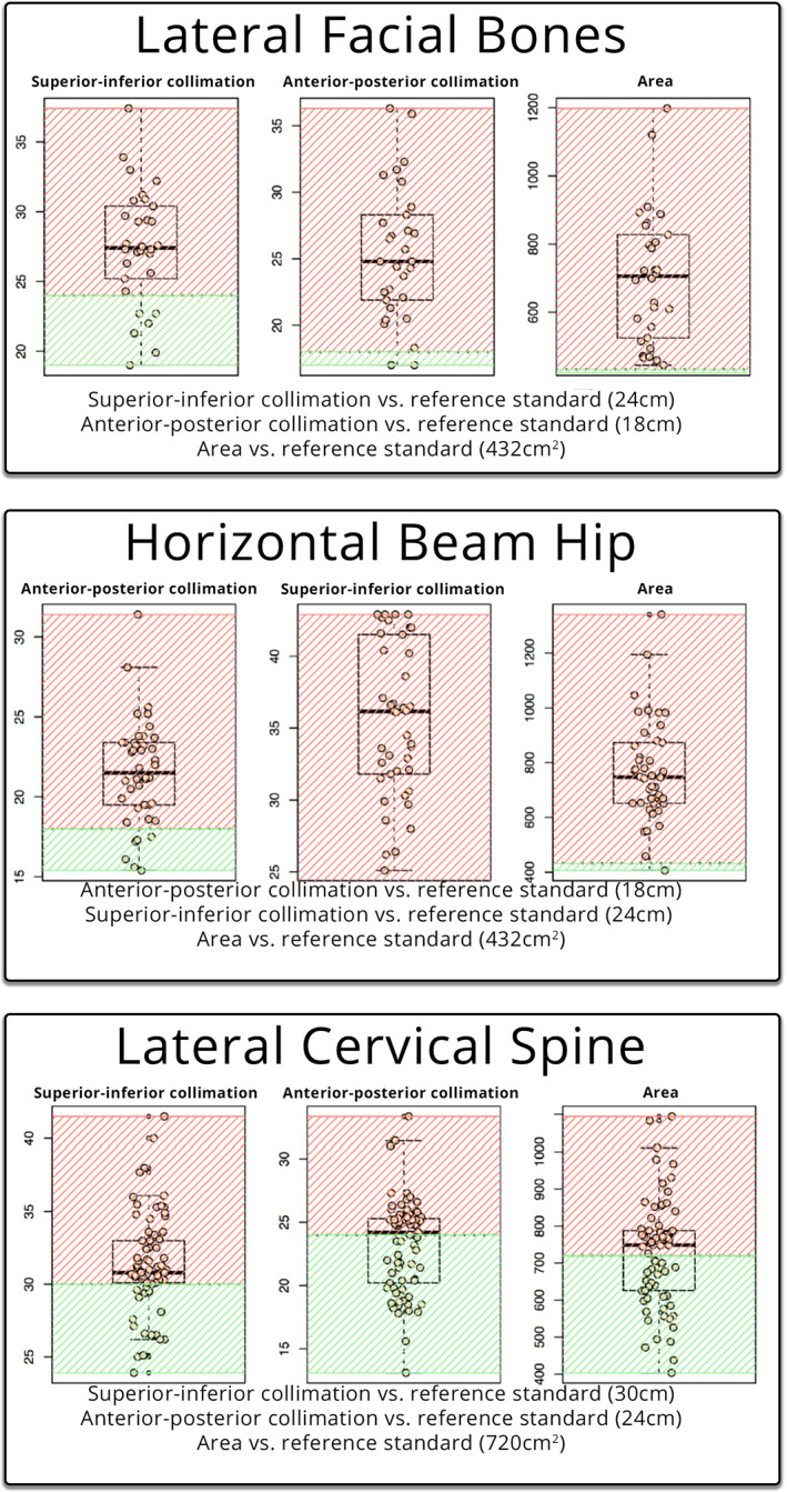
Box and whisker plots of the lateral facial bones, horizontal beam hip and lateral cervical spine. Each dot represents an observation on the plot line. Green represents within the reference standard, red outside the reference standard.
A similar theme of utilising electronic cropping to replicate properly collimated images was observed with the lateral facial bone projection. Image B of Figure 4 was sent to PACS depicting a properly collimated image, however, after removing the electronic cropping, the EFOV of the primary x‐ray beam had a measured area of 27.5 × 32.3 cm corresponding to an EFOV of 888.25 cm2, 205% of the appropriate cassette size. It can be postulated that cropping the image may have been done for aesthetic purposes, as demonstrated in a study by Hayre et al, which found that radiographers cropped their x‐rays to improve the aesthetic appearance of the image, with little regard to the dose implications of over‐collimating. 8
Ninety‐nine examinations were assessed against the reference standard (30 cm × 24 cm = 720 cm2), the summary description can be seen in Table 1. The visualisation of the data is presented in Figure 1 against the reference standard (in green).
Secure .gov websites use HTTPS A lock ( Lock Locked padlock icon ) or https:// means you've safely connected to the .gov website. Share sensitive information only on official, secure websites.
When measured against the reference standard, supero‐inferior collimation was lower or equal to the limit in a total of six patients (20%), whilst twenty‐four patients (80%) were above the limit. The antero‐posterior collimation was lower or equal to the limit in a total of two patients (6.67%), whilst twenty‐eight patients (93.3%) were above the limit. The EFOV was lower or equal to the limit in zero patients (0%), with all thirty (30) patients (100%) being above the limit.
This retrospective study assessed if the exposed field of a radiographic examination was larger than a reference standard across five different projections on different body types, with the reference size being the corresponding cassette size used in traditional computed radiography. This study found that patients are being over‐exposed to radiation due to inadequate collimation of the primary beam. The ability to digitally crop an image results in exposed anatomy not being examined by clinicians. Digital radiography presents a unique opportunity to conduct audits in this area.


 Ms.Cici
 8618319014500