
Bright Lights, Big City - bright illumination
Strobe Lightfor Car
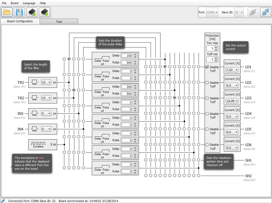
The LTDVE series can also be configured via the RS485 communication interface that implements the Modbus/RTU slave protocol.
LTDV controllers accurately set current intensity, pulse duration and delay of LED illuminators, offer filtering options for trigger signals and easily synchronize the strobe pulses with the camera exposure to meet today’s machine vision high speed demands.
LEDStrobe ControllerModule
EmergencyStrobe Light Controller
Your browsing behavior is tracked across websites by advertising and social network service providers. You may see tailored advertising and content on other websites based on your browsing profile.
The configuration is stored in a non-volatile memory to maintain your settings even when the Ethernet or RS485 connection is removed.
LTDV6CH can be configured via RS485. You can either download and use our free LTSW software to configure the controller from your PC or directly send low-level commands from a PC using the Modbus/RTU slave protocol (all the Modbus function codes supported by the controller are listed in the manual available online).
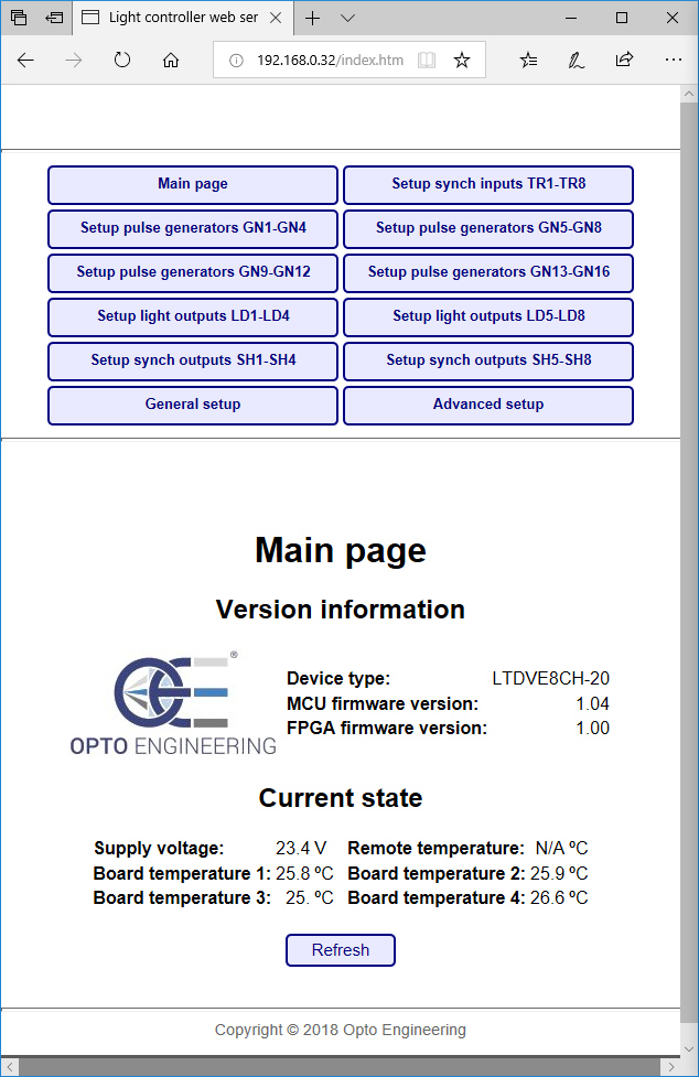
Opto Engineering® LTDVE series of controllers can be configured via Ethernet or RS485.With the Ethernet interface, you can configure the controller with either the Modbus/TCP slave protocol or the internal web browser. The second option allows for a very easy configuration of the controller using a common web browser to visually change the parameters and/or inspect the device status.
Strobe ControllerFlasher Module
Option A) shows a triggering arrangement where the light controller, once triggered by one or more trigger sources (i.e. the sensor positioned on the manufacturing line), triggers the camera(s). The advantage of such an arrangement is that the controller can filter the trigger signals before passing the command to the camera and the light.
Your browsing behavior is tracked across websites by advertising and social network service providers. You may see tailored advertising and content on other websites based on your browsing profile.
Option B) shows an arrangement where each camera is first triggered by a trigger source (i.e. the sensor positioned on the manufacturing line), and then it triggers the light controller and starts its exposure.
Opto Engineering® range of strobe controllers offers repeatable fast pulsing for quick and accurate strobing of a wide variety of LED lightings.
VAT IT02011230204 Fiscal code and registration number at Mantova Business Register 02011230204 Nr. REA: MN-216669 - Share Capital: 205.258,00 €
LTDV1CH-17V is simply configured from the front panel via DIP switches. You can easily set the intensity of the LED lights driving current (from 5mA to 17A), filtering option for the trigger signal (select between 10 µs or 100 µs time constant) and delay for synchronization output (select between 0 or 100 µs).
We collect statistics to understand how many visitors we have, how our visitors interact with the site and how we can improve it. The collected data does not directly identify anyone.
We collect statistics to understand how many visitors we have, how our visitors interact with the site and how we can improve it. The collected data does not directly identify anyone.

Our website uses cookies which are necessary for running the website and for providing the services you request. We would also like to set the following optional cookies on your device. You can change these settings any time later by clicking "Change cookie settings" at the bottom of any page. For more information, please read our privacy notice.
Strobe Controller12V
LTDV controllers are designed to get the very best out of Opto Engineering® LED lighting solutions, both in terms of brightness stability and precise control.
Opto Engineering® LED strobe controllers include LTDVE with Ethernet and RS485 interfaces featuring one, two, four and eight output channels to drive lights with currents up to 40A pulsed and 4A continuous and LTDV1CH-17V featuring one single channel, simple DIP switch interface and designed to drive lights with currents from 5mA up to 17A.
Two typical camera triggering arrangements (Option A and B) are illustrated for each controller model. Triggering Option A is preferred because the controller directly filters the trigger signals getting rid of unwanted noise. This configuration is possible because Opto Engineering® controllers feature dedicated synchronization outputs which are not commonly available from other manufacturers.
Strobe Controllerfor LED lights
We store choices you have made so that they are remembered across visits in order to provide you a more personalized experience.
The following diagrams explain how to connect Opto Engineering® strobe controllers with the other machine vision components: LED lights, cameras, power supply and PC (for the configuration of all the parameters).
We store choices you have made so that they are remembered across visits in order to provide you a more personalized experience.
To use LTSW configuration software your PC must have a native RS485 communication interface or a suitable RS485/USB converter must be used (PN: ADPT001)


 Ms.Cici
 8618319014500