
Practical Optical Camera Communication Behind Unseen and ... - optica camera
The convergent center of the object space chief ray parallel to the optical axis is located infinitely far away from the image space, which is called the object space telecentric light path. Its function is: it can eliminate the reading error caused by inaccurate focusing of the object.
Thin lensmagnification equation
Illustration of the basic geometry of image formation is given on FIG. 10. From the geometry of either thin lens or mirror, image vs. object transverse magnification M=hI/hO=I/O, with I, O being, as before, image and object distance, respectively.
Designing a telecentric industrial lens for parallel-light imaging is not complicated in theory, but it is another matter to achieve a certain resolution and imaging quality. The telecentric lens design and manufacture is indeed more difficult than a lens in the general sense. The reason is that the size of the optical lens of the telecentric lens is relatively large, which makes the correction of various phase differences of the edge light more difficult.
The purpose of telecentric lens design is to eliminate the difference in magnification caused by the inconsistency of the distance between the measured object and the lens. And different telecentric lenses will need different telecentric designs.
It integrates the dual functions of object space/image space telecentricity, and is mainly used in the field of vision measurement and detection. Bi-telecentric lens, which is also called a double telecentric lens, adopts this principle.
There was a view that the telecentric lens mainly solves the distortion problem. In fact, the telecentric lens solves not only the distortion problem, but the low distortion is only an additional attribute of the telecentric lens. The unique optical characteristics of the telecentric lens: when the object moves in the field of view, its magnification in different positions will not change, which determines that it cannot be replaced by ordinary industrial lenses in some fields. For example, its larger depth of field can be well adapted to the working environment on site, which is not a problem that can be solved only by algorithms.
with Rm being the mirror radius of curvature. According to the sign convention, both, mirror radius of curvature and its focal length are numerically negative. While it is usually applied to the radius, mirror focal length is often given positive, for practical reasons.
FIGURE 9: The geometry of refraction/reflection leading into the fundamental relation of Gaussian approximation (all angles are exaggerated for clarity). O and I are object and image distance, respectively, n and n' are index of refraction before and after refraction/reflection, respectively, and R is surface radius of curvature; φ
Thin lens approximationformula
For a given surface radius R, image and object distance are in inverse relation; the image of farther away objects is closer to the objective. As the object distance O approaches infinity, image distance I reduces to the focal length I=R/[1-(n/n')]=f. The focal point is called paraxial, or Gaussian focus. This relation is derived from the geometry of refracting (or reflecting) ray, illustrated below, for reflecting and refracting surface of similar radius of curvature (FIG. 9).
Thin lens approximationexample
with nO and nI being the refractive index of object and image space, respectively. For lens, nO=nI=1, and for mirror nO=1 and nI=-1; image separation I is positive for the former, negative for the latter. Object distance O is negative for both.
FIGURE 10: Geometry of image formation by thin lens (A) and mirror (B) in air. Incident ray parallel to the optical axis (2) is directed, after reflection or refraction, to the focal point F, located at its intersection with the optical axis. It determines the focal length f. Incident ray 3 coming from the same object point through the front focus F' or F refracts or reflects parallel to the optical axis; its intersection with ray 2 determines the image point location. Alternatively, it is also determined by the point of intersection with the incident ray arriving at the center of the objective (1, the chief ray). As object distance increases, incident rays coming through the front focus and center of the objective (3 and 1, respectively) merge closer, practically merging together for very distant objects. At that point, image magnification, given as image-to-object-distance ratio, approaches zero - with the field angle α reduced to a very small, but finite quantity - and the image practically forms in the focal plane. The height hi of the point-image of a point-object producing an oblique incoming pencil is a product of the incoming angle a and lens-to-image separation, hence for any given angle proportional to lens-to-image separation. Inset at top left in (A) shows formation of virtual image; unlike real image, which is formed by converging rays, virtual image is formed by projecting diverging rays in opposite direction. Shown is virtual image of the object inside lens' focal length; unlike real image, virtual image is erect and on the same side as the object. Bringing object still closer results in its virtual image shift toward it, with the two coinciding for the object at the surface. Virtual image is also formed by a negative lens and object farther than its focal length from it. In the presence of an optical surface, or element, following the surface/element producing virtual image, such image becomes its virtual object . When the lens thickness is significant with respect to the object distance and focal length, the ray path through the lens becomes a factor in determining lens' focal length f, and needs to be taken into account (C). Here, focal length equals the separation between 2nd principal plane - a plane normal to the axis, containing the point of intersection (principal point P2) of extended path of a collimated incident ray and reversed path of it after exiting the lens - and the focal point (F'). It is preceded by the 1st principal plane, determined in the same manner with collimated incident ray from the opposite direction (principal point P1). The corresponding points on the two principal planes are always at the same separation from axis, i.e. lay on a line parallel to it; in effect, all rays refracted by a lens behave as if the only refraction is taking place at the principal plane. A ray whose incident and final orientation doesn't change (in other words, its path before and after lens are parallel) determines lens' nodal points. For a single lens, nodal points lay in the principal planes, 1st nodal point (N) in the 1st principal plane, and 2nd nodal point (N') in the 2nd principal plane. Principal planes are not necessarily contained within lens, and may be located at a significant distance from it (for instance, with Maksutov corrector). Also, in unequifocal lenses or systems, such as human eye, with different incident and final medium refractive index (thus different focal lengths in these respective media), nodal points are displaced axially from the principal planes, although the nodal points separation remains identical to that of the principal planes, Note that the above scheme is a paraxial (Gaussian) idealization, ignoring lens' aberrations, thus only valid for paraxial rays.
The convergent center of the chief ray of the image side parallel to the optical axis is located infinitely far away from the object, which is called the image-side telecentric light path. Its function is to eliminate the measurement error caused by the inaccurate focusing on the image side.
Relation between object distance O, image separation I and objective's focal length f can be expressed in a general form given by the Gaussian lens formula as:
Likewise, for two thin lenses at a separation L, image forms at an effective distance (measured from the rear lens) I=(Lf2-xf1f2)/(L-xf1f2), where x=O/(O-fC). For large object distance O, x=1 and I=fb, with fb being, as before, the back focal length, i.e. the rear-lens-to-image separation:
Thin lens approximationequation
In the paraxial, or Gaussian approximation, the image of a point is assumed to be formed by the rays close to optical axis - paraxial rays - for which sine of the angle practically equals the angle itself (in radians). Replacing sine by the angle simplifies the expressions for refraction and reflection (Snell's law), allowing for quick, yet accurate assessment of basic spatial and geometric image properties, derived from the pupil-to-image separation. Since it effectively uses only a small central portion of the optical surface, it does not provide information on image quality, i.e. aberrations. In aberration-free systems, Gaussian and actual focus coincide.
How to choose the right telecentric lens design? First of all, the lens-compatible CCD size should be equal to or larger than the camera sensor size; Secondly, calculate the mag when the object size and camera sensor size are confirmed, always choose a smaller mag if no existing suitable mag so as to cover all the object area. Finally, check the WD & lens size to make sure it can fit in the whole system's design. Pay attention to other requirements like distortion, or DOF if necessary.
The image resolution is generally measured by the CTF (contrast transfer function) that quantifies the existing spatial frequency contrast of the image sensor, and the unit is lp/mm. Most machine vision integrators often just gather a large number of cheap low-pixel, low-resolution lenses, and finally can only generate blurred images. With a telecentric lens, even with a small pixel image sensor, high-resolution images can be generated.
Thin lens approximationgraph
The relation is still valid for two thin lenses separated by a small air-space, For all practical purposes, it also applies to a cemented lens (with f1 and f2 being the respective focal lengths in air), since the effect of denser exit media for the front lens is, for all practical purposes, offset by the denser incident media for the rear lens.
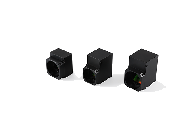
Telecentric lens has three catagories, object space telecentric, image space telecentric and bi telecentric lens. The difference between these three kinds lies in that the chief ray which is parallel to the optical axis is on the object space, or in the image side, or in both the object and image spaces. Object space telecentric lens and bi telecentric lenses are the most popular telecentric lens in applications.
This expression is referred to as thin lens equation, or lensmaker's formula. It can be also written without inverted radii as fl=R1R2/(nG-1)(R2-R1). Note that in the standard right-hand Cartesian coordinate system distances to the left are negative, and those to the right positive; consequently, biconvex lens has the front radius positive and the rear radius negative.
The corresponding combined focal length is determined by the point of intersection between the marginal ray of axial cone converging toward focal point extended backward to a parallel-to-optical-axis line drawn from the end point of the front lens aperture, i.e. it is larger than the back focal length by a factor 1/[1-(L/f1)]. Mirror focal length fm, after substituting n=1 and n'=-1 (for incident light traveling from left to right, according to the sign convention) in Eq. 1, resulting in (1/I)=-2/R=1/fm, is defined as: with Rm being the mirror radius of curvature. According to the sign convention, both, mirror radius of curvature and its focal length are numerically negative. While it is usually applied to the radius, mirror focal length is often given positive, for practical reasons. Relation between object distance O, image separation I and objective's focal length f can be expressed in a general form given by the Gaussian lens formula as: For thin lens, the sign is positive for real object, image and focal length, and negative when they are virtual. It is also valid for mirrors and objectives in general, under the same assumption that object distance and focal length of a converging cone are both numerically positive, with image separation being determined according to their specific values (positive for O>f, negative - indicating diverging imaging cone - for O
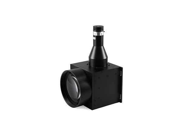
Telecentric Lens is an optical design that the principal ray is in parallel to the optical axis. Because of these characteristics, the main advantages of the telecentric lens is to eliminate distortion when off-focus and provide superior image performance when doing high precision measurement and inspection.
Thin lensequation derivation
Image separation for an imaging surface, refracting or reflecting, is obtained from this basic equation relating object distance O, single optical surface radius of curvature R and image-to-surface separation I:
As noted, both above expressions apply when the imaging medium is air, a common circumstance. In general, focal length is, from Eq. 1.4, defined by f=nIO/(I+O), with n being the refractive index of the imaging medium. Hence, nominal focal length increases with the medium refractive index. However, due to the change in the effective wavelength - which compresses inside denser media, and vice versa, resulting in the correspondingly smaller diffraction pattern, the effective focal length remains identical to that in air, i.e. smaller by a factor of n (an example being the optical system of human eye).
I1 being the front surface to (its) image separation, and R1 being the front surface radius of curvature. For a very distant object, 1/O is infinitely small, and its image forms at a distance I1=nR1/(n-1) from the first surface. This is now the object distance O for the second surface (n=nG and n'=1), which will form the final image at a distance I2, equal to the lens' focal length fl according to (1/I2)=1/f=[(nG-1)/R1]-(nG-1)/R2, which comes to:
Transverse magnification MT of the image formed by optical surface is given as a ratio of the image vs. object height, MT=h'/h. With h=Iτ', where I is the image separation and τ' the refracted/reflected angle, and h=Oτ, where O is the object separation and τ the angle of incidence, MT=Iτ'/Oτ. Since, according to the Snell's low, in paraxial approximation τ'=(n/n')τ, with n and n' being the refractive index of incident and transmitting media, respectively, transverse image magnification can be written as MT=nI/n'O. Since O, I and n' are numerically negative for mirror surface, and O is numerically negative for refractive surface, transverse magnification is for both numerically negative, i.e. image orientation is opposite to that of the object. As before, parameters related to the reflected ray have subscript M (for mirror) and those related to the refracted ray subscript G (for glass); the illustration assumes common scenario where either surface is in air (n=1). Angular magnification MA is defined as a ratio of the angle between axis and a ray connecting the axial object and image point through a given surface zonal height z, the angle at the image vs. angle at the object, or MA=φ'/φ. With φ=z/O and φ'=z/I, it can be written as MA=O/I. Hence, MTMA=n/n' and, substituting MT=h'/h and MA=φ'/φ, gives n'h'φ'=nhφ. In other words, change of these three parameters in the transmitting vs. incident medium offset one another, and the quantity nhφ, called Lagrange invariant, doesn't change with reflection/refraction.
For thin lens, the sign is positive for real object, image and focal length, and negative when they are virtual. It is also valid for mirrors and objectives in general, under the same assumption that object distance and focal length of a converging cone are both numerically positive, with image separation being determined according to their specific values (positive for O>f, negative - indicating diverging imaging cone - for O
The three pairs of points illustrated on FIG. 10 - object space and image space focal point (F and F'), 1st and 2nd principal plane points (P1, P2) and 1st and 2nd nodal point (N, N') are called six cardinal points of a lens or imaging system. These points describe its Gaussian imaging. For thin lens, or mirror, a single cardinal point - the focal point - suffice. Thick lens also requires specified principal planes, and systems where nodal point are not contained in the principal plane, require in addition specified nodal points, for determining the angle between object point and the corresponding image point (axis of object orientation, such as visual axis of human eye), as well as the image space focal point. ◄ 1.3. Optical system of a telescope ▐ 2. MAIN FUNCTIONS OF A TELESCOPE ► Home | Comments
For thin lens in air, first surface indici are n=1 for light traveling from left to right, and n'=nG, nG being the glass refractive index, so Eq. 1 applied to the first surface becomes
Types ofthinlenses
Gaussian approximation is strictly valid only for rays close to the optical axis - paraxial rays - and used to determine their points of convergence. In principle, these points coincide with the points of convergence of a perfect (aberration-free) system. While Gaussian approximation does not provide direct information about image aberrations, it is a quick, practical way of determining location of the paraxial focus of an optical surface, or element.

Mirror focal length fm, after substituting n=1 and n'=-1 (for incident light traveling from left to right, according to the sign convention) in Eq. 1, resulting in (1/I)=-2/R=1/fm, is defined as:
In paraxial approximation, angles are small enough that their sines correlate as the angles themselves. Thus the Snell law of refraction, nsinα=n'sinα' simplifies to nα=n'α', leading to the equality δ=φ-α=φ'-α', with δ being the angle between the surface normal and the axis, φ, α the incident ray angle with the axis and surface normal, respectively, and φ', α' the angle of refracted/reflected ray to the axis and normal, respectively (according to the sign convention, αM, δG and φ'G are numerically negative; applying sign convention makes possible to use the same relations for both, reflection and refraction). With α=φ-δ and α'=φ'-δ, substituting into the simplified Snell's law gives n(φ-δ)=n'(φ'-δ)=n'φ-nδ=(n'-n)δ which, after replacing the angles with the appropriate height/distance ratio (φ=h/O, δ=h/R and φ'=h/I, with the common ray height h at the surface cancelling out), leads into Eq. 1.
Focal length ofthin lensformula
In this, form, however, the relation is not generally applicable; for instance, a concave mirror surface oriented to left forms the real image, but its image separation and focal length (for object at infinity) are also measured from right to left, thus numerically negative in the standard coordinate system. Likewise, object distance, if measured from the aperture stop is also numerically negative. In order to make this expression generally applicable, and useable in chosen sign convention, it needs to be modified to:
Alternately, it can be expressed as a complete (thick lens) formula, for n0, n1, n2 being the refractive index of object space, lens and image space, respectively, 1/f=[(n1-n0)/n2R1]-(n1-n2)/(n2R2)[1-(n1-n0)t/n1R1], where t is the lens axial thickness. For relatively small t, analogously to lens immersed in air, it simplifies to the thin lens formula, 1/f=[(n1-n0)/n2R1]-(n1-n2)/n2R2.
In order to obtain a good image quality of the edge field of view, higher product design and manufacturing accuracy is required, and in many cases it is necessary for the designer to have relatively rich design experience.
For very distant objects, 1/O approaches zero, and O/(I+O) approaches 1, with the focal length f and image separation I practically coinciding. Evidently, the relation directly implies that the closer the object, the farther from the objective its image.
From Eq. 1, paraxial image distance formed by a single refractive or reflective surface of radius R, for object space refractive index n and image space refractive index n' is I=n'/[(n/O)+(n'-n)/R]. For lens in collimated light, n/O is zero for the first surface, and image formed by it effectively becomes object for the second surface, with the latter forming the final image if this object at the distance equaling focal length. Denoting refractive indici from the object space to the image space as n1, n1' (at the front lens' surface) and n2, n2' (at the rear surface), the focal length is given by f=n2'/{[(n2'-n2)/R2]+(n1'-n1)n1/n1'R1}, with R1 and R2 being the front and rear surface radius of curvature, respectively.
with n and n' being the refractive index before and after reflection or refraction, respectively. This gives the image separation I=n'RO/[(n'-n)O+nR]. In other words, n is the index of incident medium, and n' is index of the refractive or reflective medium. Numerically, either is positive for light traveling from left to right, and negative for the opposite direction (also, according to the sign convention, object or image distance is negative when either is to the left of surface, positive when to the right).
This implies that the focal length of thin lens equals lens-to-image distance with object at infinity, i.e. far enough that the rays coming from it are practically parallel. Based on these same principles, with the object for the rear lens being the virtual image formed by the front lens, focal length fC of two thin lenses in contact, in terms of their focal lengths f1 and f2 is:


 Ms.Cici
 8618319014500