
Advanced Illumination - DL080 - Large Area Diffuse Light - dl080
Framegrabber vendors provide configuration files templates for each camera mode of operation. A mode of operation describes the way the camera is controlled and how the data are sent to the framegrabber.
The CoaXPress (CXP) standard was released in December 2010. It provides a high speed interface between cameras and frame grabbers and allows long cable lengths. In its simplest form, CoaXPress uses a single coaxial cable to: transmit data from a camera to a frame grabber at up to 6.25 Gbits/s; simultaneously transmit control data and triggers from the frame grabber to the camera at 20.8 Mbits/s; and provide up to 13W of power to the camera. Link aggregation is used when higher speeds are needed, with more than one coaxial cable sharing the data. Version 1.1 allows use of the smaller DIN 1.0/2.3 connector.
Connectors available for GigE Vision: Copper Ethernet; Copper Ethernet with vision locking screws; 10 Gigabit Ethernet direct attach cable; Ethernet fiber optic cable.
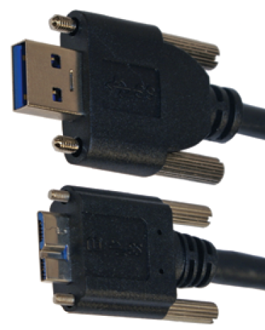
Digital camera USBcable types
The Camera Link standard was initially released in 2000. It is a robust, well-established communications link that standardizes the connection between cameras and frame grabbers and defines a complete interface, including provisions for data transfer, camera timing, serial communications, and real-time signaling to the camera. Camera Link is a non-packet-based protocol and remains the simplest camera/frame grabber interconnect standard. Currently, in version 2.0, the standard specification includes Mini Camera Link connectors, Power over Camera Link (PoCL), PoCL-Lite (a minimized PoCL interface supporting base configurations) and cable performance specifications.
Per leggere la targa di un'automobile in avvicinamento bisogna che l'altezza dell'auto sia alta almeno il 50% dell'area globale che appare sul monitor
USB digital camerasoftware
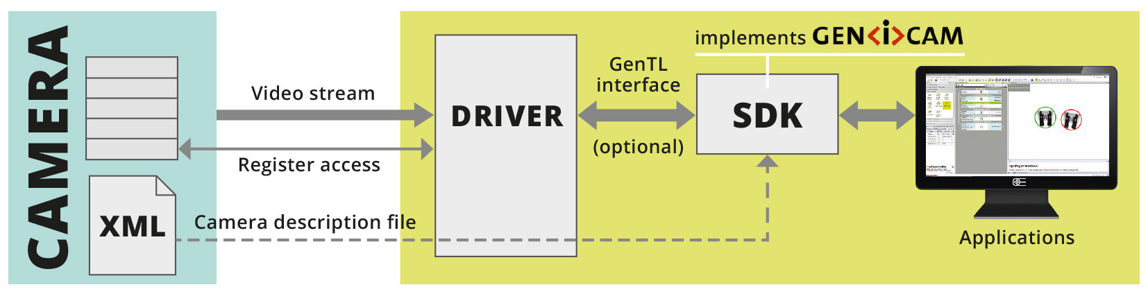
GenICam (Generic Interface for Cameras) provides a generic programming interface for all kinds of cameras, no matter what hardware interface technology is used or what features are implemented. The objective of GenICam is to have the same application programming interface (API) used throughout the industry.
The “Base” Camera Link configuration carries signals over a single connector/cable. The cable carries 5 LVDS signals for video data streaming (24 bits of data + 4 framings/enable bits), 4 LVDS control signals and 2 LVDS for asynchronous serial communication (UART).
Per rilevare la presenza di una persona bisogna che l'altezza della figura sia alta almeno il 10% dell'area globale che appare sul monitor
The GigE Vision standard is a widely adopted camera interface standard developed using the Ethernet (IEEE 802.3) communication standard. Released in May 2006, the standard was revised in 2010 (version 1.2) and 2011 (version 2.0). GigE Vision supports multiple stream channels and allows for fast error-free image transfer over very long distances using standard Ethernet cables.
Through standard passive copper cable 4.5W (5V, 950 mA) maximum; power supply through active copper varies, no power supply through multi-mode fiber optic.
Point and shootcamera withUSB-C
Per riconoscere una persona conosciutabisogna che l'altezza della figura sia alta almeno il 50% dell'area globale che appare sul monitor
Camera Link defines its own dedicated cable. Cameras and frame grabbers can be easily interchanged using the same cable. The maximum cable length is in the range of 7 to 15 meters depending on the camera clock rate.
Domanda: "Vorrei riprendere con una telecamera da 1/3" un'area larga 8 metri che si trova a 13 metri di distanza dall'obiettivo"Risposta: Focale corretta (mm) = 13 x 4,8 : 8 = 7,8 mm. L'obiettivo più adatto avrà focale 8 mm. Domanda: "Vorrei riprendere con una telecamera da 1/4" un accesso largo 6 metri che si trova a 7 metri di distanza dall'obiettivo" Risposta: Focale corretta (mm) = 7 x 3,6 : 6 = 4,2 mm. L'obiettivo più adatto avrà focale 4 mm. Nel nostro sito è disponibile il calcolatore per obiettivi che esegue automaticamente questi calcolo.
SpeedCoaXPress supports real-time triggers, including triggering very high speed line scan cameras. With the standard 20.8 Mbits/s uplink to the camera, trigger latency is 3.4 microseconds (μs), or with the optional high speed uplink, it is typically 150 ns. CoaXPress already supports the fastest cameras on the market with significant headroom by allowing up to 3.6 Gbytes/s with 6 links in one connector.
Nel paragrafo precedente si è visto come calcolare che obiettivo ci serve per inquadrare un certo target, cioè una certa area. Ma come determinare quanto deve essere grande quest'area? Sicuramente potrete farvi guidare dall'intuito sulla base di cosa pensate abbia interesse controllare, però dovete anche tenere presente le vostre esigenze di identificazione. Di seguito riportiamo una guida utile.
Support for GenICam, including GenApi, SFNC, and GenTL (including image streaming) is mandatory. IIDC2 support is optional.
The framegrabber is configured by means of a configuration file that contains all the parameters relative to the specific camera we want to communicate with. Configuration files are vendor-specific (framegrabber) and can have different formats. Usually, they’re text files that can be opened with any text editor.
In order to correctly receive and interpret the stream of video data, the camera and framegrabber must be configured in a coherent way. Image width and height, bit depth, pixel format, read out “taps”, connection speed (clock) and camera link modes need to be correctly configured in both devices. Failing to do so leads to artifacts and useless images.
The USB3 Vision standard was initiated in late 2011, with version 1.0 published in January 2013. While the standard is new, the machine vision industry is not unfamiliar with USB technology. The USB interface brings broad levels of consumer awareness, easy plug and play installation, and high levels of performance. The expertise of many companies was combined to create a standard that accommodates the varied needs within the machine vision industry. This approach allows off-the-shelf USB host hardware and nearly any operating system to take advantage of hardware direct memory access (DMA) capabilities to directly transfer images from the camera into user buffers. Leveraging camera control concepts from the GenICam standard means end users can easily implement USB3 Vision into existing systems. With the USB-IF organization’s established track record of continuously updating the USB standard to improve speed and add features (USB 3.1 has already been released which doubles the speed), USB3 Vision will continue to leverage these improvements.
VAT IT02011230204 Fiscal code and registration number at Mantova Business Register 02011230204 Nr. REA: MN-216669 - Share Capital: 205.258,00 € 沪ICP备12040578号-2
The widely used BNC connector and smaller DIN 1.0/2.3. The DIN connector can also be combined into a multiway connector.
I parametri indicati si riferiscono a una telecamera in risoluzione analogica D1 (704x576), ossia 0.4 MP. Se si utilizzano telecamere con risoluzioni superiori da 1 o 2 MP è possibile ridurre proporzionalmente le dimensioni del soggetto nel campo visivo della telecamera Riassumendo: Scegliete la grandezza dell'area da riprendere (il target) immaginando di vederla sullo schermo. Immaginate quanto risulterà alto il soggetto in proporzione allo schermo, e verificate che corrisponda alle esigenze di identificazione che avete. Può darsi che scopriate che conviene riprendere non proprio tutto il cancello, ma solo la portina di ingresso perchè questo consentirà una migliore identificazione del soggetto. Una volta stabilita base ed altezza dell'area da riprendere applicate la formula per il calcolo della focale che abbiamo visto all'inizio di questo tutorial.
Per calcolare la focale adatta alle vostre esigenze e quindi scegliere l'obiettivo, è innanzitutto necessario misurare la dimensione dell'area da riprendere e la sua distanza dall'obiettivo. L'area di interesse viene chiamata TARGET e non è necessariamente la dimensione del muro o del cancello di fronte alla telecamera, ma piuttosto la zona dove immaginate possano avere luogo gli eventi che avete interesse a riprendere. Più avanti vi daremo alcuni consigli su come determinarla, ma per il momento diamola per acquisita. Per calcolare la focale valgono le seguenti formule:
Members of the GenICam standard group maintain a reference implementation that parses the file containing the self-description of the camera. The production quality code is written in C++, and can be used free of charge. It is highly portable and available on a range of operating systems and compilers. Most available SDK implementations use this reference implementation as the engine under the hood, thus ensuring a high degree of interoperability.
Since there are better alternatives it has became an obsolete interface and it’s no longer used for new design. Furthermore, It’s no longer integrated in modern PC motherboards, wiping out the advantage of the low cost.
Camera Link was built for real-time, high-speed communication. The high bandwidth of 255 Mbytes/s for one cable and up to 850 Mbytes/s for two cables assures fast transfer of images with no latency issues.
various data rates. Other Ethernet standards, such as IEEE 1588 (namely PTP, Precision Time Protocol), are leveraged to provide deterministic triggering.
The standard builds upon the inherent aspects of USB 3.0, bringing end-to-end data reliability at over 400 Mbytes/s. The recently approved USB 3.1 standard more than doubles this effective speed but adoption has not yet started.
At 1.25 Gbits/s link speed (CXP-1), CoaXPress supports cable lengths of over 100m; at 3.125 Gbits/s (CXP-3), the maximum length is 85m; and even at the maximum 6.25 Gbits/s (CXP-6), 35m cables with 6mm diameter can be used. Longer lengths are possible with larger diameter cables.

PC (direct), with GigE interfaces built into almost all PCs and embedded systems, no additional interface card (frame grabber) is necessary in many situations.
MiniUSB
In these configurations, a second connector/cable is added. In “Medium” configuration this provides 24 bits for additional video data and the same 4 framings/enable bits as in “Base” configuration. This yields a 48-bit data path capable of throughput up to 4.08 Gbps (510 MBps). In “Full” configuration another 16 bits are added, resulting in a 64-bit data path that can carry 5.44 Gbps (680 MBps).
Currently 1 and 2 Gbits/s (using 2 cables) systems are readily available with a number of 10 Gbits/s and wireless systems now entering the market.
Camera Link comes in several variants which differ in the amount of data that can be transferred. Some of them require two cables for transmission. The frequency of the data transmission starts from 40 MHz for old/cheap cameras/framegrabbers and can reach 85 MHz for the latest devices. All the following data refers to the operating frequency of 85 MHz.
The other 16 bits for video data are added, eliminating redundant control signals and taking advantage of unused wires. This yields an 80-bit data path capable of throughput up to 6.80 Gbps (850 MBps).
Depending on the cable and number of cameras, GigE Vision allows cable lengths up to 100m (copper) and 5,000m (fiber optic) using a single camera.
Camera Link has optional GenICam support for plug and play interoperability. The use of up to two cables per camera is possible.
Per identificare una persona sconosciuta bisogna che l'altezza della figura sia alta almeno il 120% dell'area globale che appare sul monitor
PC (direct). With USB interfaces built into almost all PCs and embedded systems, no additional interface card (frame grabber) is necessary in many situations.
IEEE 1394, also known as FireWire, is a legacy interface based on a technology developed by Apple Inc. in 1987. There are two types of IEEE 1394: IEEE 1394a and IEEE 1394b. For the machine vision market, IIDC is the FireWire data format protocol that defines the layout of the control registers inside the camera. The current version of IEEE 1394-IIDC (1.32) is multi-camera capable and offers connectivity of up to 63 devices per bus.


 Ms.Cici
 8618319014500