
my ocs - usarea pokemon 2 - usarea
CS-mount is a less popular and 5 mm shorter version of the C-mount, with a flange focal distance of 12.526 mm. A CS-mount camera presents various issues when used together with C-mount optics, especially if the latter is designed to work at a precise back focal distance.
Figure 1. (a) Chromatic aberration is caused by the dependence of a lens’s index of refraction on color (wavelength). The lens is more powerful for violet (V) than for red (R), producing images with different locations and magnifications. (b) Multiple-lens systems can partially correct chromatic aberrations, but they may require lenses of different materials and add to the expense of optical systems such as cameras.
The focal length is a typical characteristic of an optical system. It is a measure of how strongly the system converges or diverges rays of light. If collimated rays converge to a physical point, the lens is said to be positive (convex), whereas if rays diverge the focus point is virtual and the lens is said to be negative (concave). All optics used in machine vision applications are overall positive, i.e. they focus incoming light onto the sensor plane. CCTV lenses are commonly identified by their focal length, expressed in millimeters (12mm, 25mm, 35mm, etc.).
C-mount is the most common optics mount in the industrial market. It is defined by a flange focal distance of 17.526 mm, a diameter of 1” (25.4 mm) with 32 threads per inch.
where p is the sensor pixel size (in microns), M is the lens magnification and k is a dimensionless parameter that depends on the application (reasonable values are 0.008 for measurement applications and 0.015 for defect inspection). For example, taking p = 5.5 µm and k = 0.015, a lens with 0.25X mag and WF/# = 8 has an approximate DoF = 10.5 mm.
HikvisionCamera
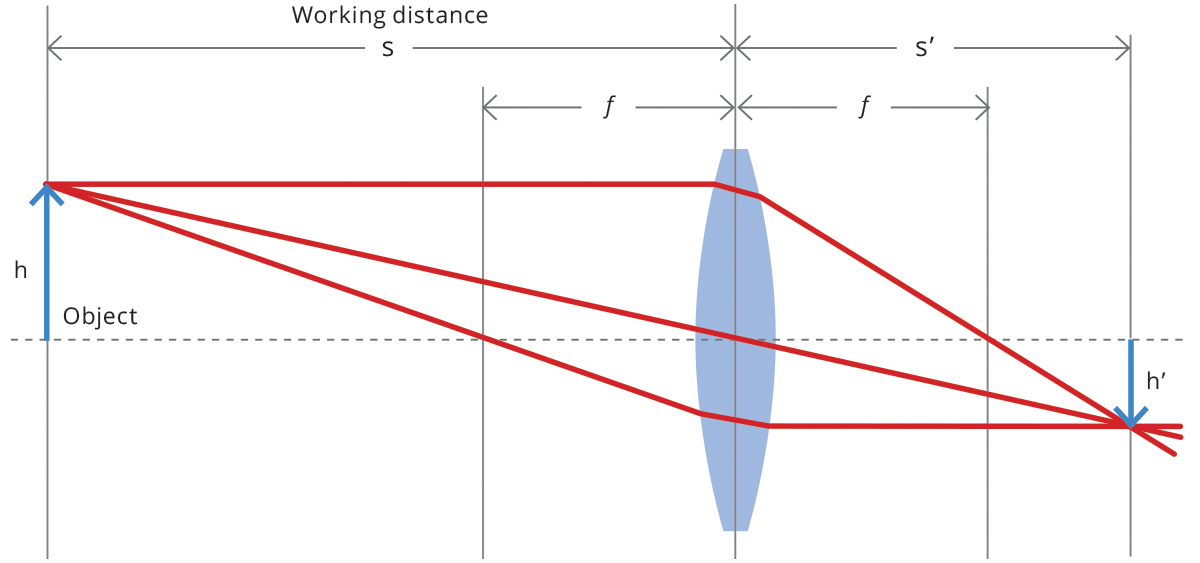
For common optical systems, in thin lens approximation, the focal length is the distance over which collimated rays coming from infinity converge to a point on the optical axis.
VAT IT02011230204 Fiscal code and registration number at Mantova Business Register 02011230204 Nr. REA: MN-216669 - Share Capital: 205.258,00 € 沪ICP备12040578号-2
where s (s’ ) is the object (image) position with respect to the lens, customarily designated by a negative (positive) value, and f is the focal length of the optical system (cf. Fig. 1). The distance from the object to the front lens is called working distance, while the distance from the rear lens to the sensor is called back focal distance. Henceforth, we will be presenting some useful concepts and formulas based on this simplified model, unless otherwise stated.
Figure 2. A coma is an aberration caused by an object that is off-center, often resulting in a pear-shaped image. The rays originate from points that are not on the optical axis and they do not converge at one common focal point.
Many cameras are found not to respect the industrial standard for C-mount (17.52 mm), which defines the flange-to-detector distance (flange focal length). Besides all the issues involved with mechanical inaccuracy, many manufacturers don’t take into the due account the thickness of the detector’s protection glass which, no matter how thin, is still part of the actual flange to detector distance.
The F-number affects the optics depth of field (DoF), that is the range between the nearest and farthest location where an object is acceptably in focus. Depth of field is quite a misleading concept because physically there is one and only one plane in object space that is conjugate to the sensor plane. However, being mindful of diffraction, aberration and pixel size, we can define an “acceptable focusing distance” from the image conjugate plane, based on subjective criteria. For example, for a given lens, the acceptable focusing distance for a precision gauging application requiring a very sharp image is smaller than for a coarse visual inspection application.
Since fixed focal length lenses also follow the previous equation, it is possible to calculate the required focal length given the magnification and working distance, or the required working distance given the sensor size, field of view and focal length, etc. (some examples are given at the end of this section). For macro and telecentric lenses instead, the working distance and magnification are typically fixed.
Figure 4. This chart can detect astigmatism, unevenness in the focus of the eye. Check each of your eyes separately by looking at the center cross (without spectacles if you wear them). If lines along some axes appear darker or clearer than others, you have an astigmatism.
Integrated Concepts. (a) During laser vision correction, a brief burst of 193 nm ultraviolet light is projected onto the cornea of the patient. It makes a spot 1.00 mm in diameter and deposits 0.500 mJ of energy. Calculate the depth of the layer ablated, assuming the corneal tissue has the same properties as water and is initially at 34.0ºC. The tissue’s temperature is increased to 100ºC and evaporated without further temperature increase. (b) Does your answer imply that the shape of the cornea can be finely controlled?
A common F-number value is F/8 since smaller apertures could give rise to diffraction limitations, while lenses with larger apertures are more affected by optical aberrations and distortion. A rough estimate of the field depth of telecentric and macro lenses (or fixed focal length lenses used in macro configuration) is given by the following formula:
Each camera mount is more commonly used with certain camera sensor formats. The most typical sensor formats are listed below. It is important to remember that these are not absolute values – i.e. two cameras listed with the same sensor format may differ substantially from one another in terms of aspect ratio (even if they have the same sensor diagonal). For example, the Sony Pregius IMX250 sensor is listed as 2/3” and has an active area of 8.45 mm x 7.07 mm. The CMOSIS CMV2000 sensor is also listed as 2/3” format but has an active area of 11.26 mm x 5.98 mm.
Real lenses behave somewhat differently from how they are modeled using the thin lens equations, producing aberrations. An aberration is a distortion in an image. There are a variety of aberrations due to a lens size, material, thickness, and position of the object. One common type of aberration is chromatic aberration, which is related to color. Since the index of refraction of lenses depends on color or wavelength, images are produced at different places and with different magnifications for different colors. (The law of reflection is independent of wavelength, and so mirrors do not have this problem. This is another advantage for mirrors in optical systems such as telescopes.)
The image produced by an optical system needs to be bright enough to be discerned. It is often a challenge to obtain a sufficiently bright image. The brightness is determined by the amount of light passing through the optical system. The optical components determining the brightness are the diameter of the lens and the diameter of pupils, diaphragms or aperture stops placed in front of lenses. Optical systems often have entrance and exit pupils to specifically reduce aberrations but they inevitably reduce brightness as well. Consequently, optical systems need to strike a balance between the various components used. The iris in the eye dilates and constricts, acting as an entrance pupil. You can see objects more clearly by looking through a small hole made with your hand in the shape of a fist. Squinting, or using a small hole in a piece of paper, also will make the object sharper.
Different mechanical mounting systems are used to connect a lens to a camera, ensuring both good focus and image stability. The mount is defined by the mechanical depth of the mechanics (flange focal distance), along with its diameter and thread pitch (if present). It’s important that the lens flange focal distance and the camera mount flange distance are exactly the same, or focusing issues may arise. The presence of a threaded mechanism allows some adjustment to the back focal distance if needed. For example, in the Opto Engineering® PCHI series lenses, the back focal adjustment is needed to adjust the focus for a different field of view.
Optical cameravs digitalcamera
Typical F-numbers are F/1.0, F/1.4, F/2, F/2.8, F/4, F/5.6, F/8, F/11, F/16, F/22, etc. Every increment in the F-number (smaller aperture) reduces incoming light by a factor of 2. The given definition of F-number applies to fixed focal length lenses where the object is located ‘at infinity’ (i.e. a distance much greater than its focal length). For macro and telecentric lenses where objects are at a closer distance, instead, the working F/# (wF/#)is used. This is defined as:
A certain number of parameters must be considered when choosing optics, depending on the area that must be imaged (field of view), the thickness of the object or features of interest (depth of field), the lens to object distance (working distance), the intensity of light, the optics type (telecentric/entocentric/pericentric), etc.
The focal length and the focus plane coincide only when the object is placed at an infinite distance, indeed beams from a point on the object can be considered as parallel. When instead the distance from the object is ‘short’ (rule of thumb: <10x Focal length), we are in macro mode and the focus plane is placed further away from the optical system compared to the focal length.
The basic purpose of a lens of any kind is to collect the light scattered by an object and recreate an image of the object on a light-sensitive ‘sensor’ (usually CCD or CMOS based).
For optical systems used in machine vision, in which rays reflected from a faraway object are focused onto the sensor plane, the focal length can be also seen as a measure of how much area is imaged on the sensor (Field of View): the longer the focal length, the smaller the FoV and vice versa (this is not completely true for some particular optical systems, e.g. in astronomy and microscopy).
50xOpticalzoom SecurityCamera
This is why a spacer kit is supplied with Opto Engineering® telecentric lenses including instructions on how to tune the back focal length at the optimal value.

The main features of most optical systems can be calculated with a few parameters, provided that some approximation is accepted. The paraxial approximation requires that only rays entering the optical system at small angles with respect to the optical axis are taken into account. The thin lens approximation requires the lens thickness to be considerably smaller than the radii of curvature of the lens surfaces: it is thus possible to ignore optical effects due to the real thickness of the lenses and to simplify ray-tracing calculations. Furthermore, assuming that both object and image space are in the same medium (e.g. air), we get the following fundamental equation:
PTZCamera
(a) 0.251 μm; (b) Yes, this thickness implies that the shape of the cornea can be very finely controlled, producing normal distant vision in more than 90% of patients.
Macro and telecentric lenses are designed to work at a distance comparable to their focal length (finite conjugates), while fixed focal length lenses are designed to image objects located at a much greater distance than their focal length (infinite conjugates). It is thus convenient to classify the first group by their magnification, which makes it easier to choose the proper lens given the sensor and object size, and the latter by their focal length.
Every optical system is characterized by an aperture stop, that determines the amount of light that passes through it. For a given aperture diameter d and focal length f we can calculate the optics F-number:
So how are aberrations corrected? The lenses may also have specially shaped surfaces, as opposed to the simple spherical shape that is relatively easy to produce. Expensive camera lenses are large in diameter, so that they can gather more light, and need several elements to correct for various aberrations. Further, advances in materials science have resulted in lenses with a range of refractive indices—technically referred to as graded index (GRIN) lenses. Spectacles often have the ability to provide a range of focusing ability using similar techniques. GRIN lenses are particularly important at the end of optical fibers in endoscopes. Advanced computing techniques allow for a range of corrections on images after the image has been collected and certain characteristics of the optical system are known. Some of these techniques are sophisticated versions of what are available on commercial packages like Adobe Photoshop.
Optical camerameaning
F-mount is a bayonet-style mount originally developed by Nikon for its 35 mm format cameras and is still found in most of its digital SLR cameras. It is commonly used with bigger sensors, e.g. full-frame or line-scan cameras. Lenses can be easily swapped out thanks to the bayonet mount, but no back focal adjustment is possible.
Mxx-mounts are different types of camera mounts defined by their diameter (e.g. M72, M42), thread pitch (e.g. 1 mm, 0.75 mm) and flange focal distance. They are a common alternative to the F-mount for larger sensors.
Quite often in an imaging system the object is off-center. Consequently, different parts of a lens or mirror do not refract or reflect the image to the same point. This type of aberration is called a coma and is shown in Figure 2. The image in this case often appears pear-shaped. Another common aberration is spherical aberration where rays converging from the outer edges of a lens converge to a focus closer to the lens and rays closer to the axis focus further (see Figure 3). Aberrations due to astigmatism in the lenses of the eyes are discussed in Vision Correction, and a chart used to detect astigmatism is shown in Figure 4. Such aberrations and can also be an issue with manufactured lenses.
Figure 1a shows chromatic aberration for a single convex lens and its partial correction with a two-lens system. Violet rays are bent more than red, since they have a higher index of refraction and are thus focused closer to the lens. The diverging lens partially corrects this, although it is usually not possible to do so completely. Lenses of different materials and having different dispersions may be used. For example an achromatic doublet consisting of a converging lens made of crown glass and a diverging lens made of flint glass in contact can dramatically reduce chromatic aberration (see Figure 1b).


 Ms.Cici
 8618319014500