
Modern Optical Engineering, 4th Ed.: Smith, Warren J. - optical engineering
The back focal point (or rear focal point) is obtained by considering a situation where the input rays (on the left side) are parallel to the optical axis. By again extrapolating the outgoing rays, one finds the back focal point (Figure 3).

Here you can submit questions and comments. As far as they get accepted by the author, they will appear above this paragraph together with the author’s answer. The author will decide on acceptance based on certain criteria. Essentially, the issue must be of sufficiently broad interest.
For a defocusing system (Figure 2), the front focal point can be located on the back side; this is a virtual focal point. It may be confusing that it is called a front focal point even though it is actually located on the back side.
For defining the front focal point, we consider a situation where the output rays (right side) are parallel to the optical axis. Here, one can extrapolate the rays on the input side (left side) and finds that they meet in one point, which is the (real) front focal point (see Figure 1).
By submitting the information, you give your consent to the potential publication of your inputs on our website according to our rules. (If you later retract your consent, we will delete those inputs.) As your inputs are first reviewed by the author, they may be published with some delay.
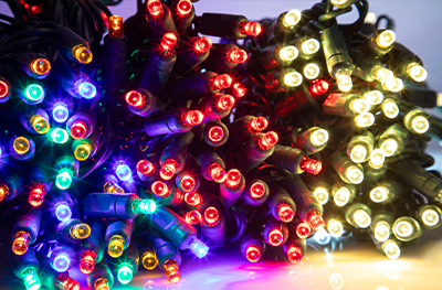
Christmas lights with 8 Functioncontroller
In Gaussian optics, one defines various types of cardinal points, to which the focal points belong. For the definition of the cardinal points, one does not consider the real light path in the optical system, but only the rays outside it, which can be extrapolated.
The focal points and planes can be found for any optical system, except if it is an afocal optical system. The front and back focal length is defined by the distance of the respective focal point from the corresponding principal plane.
4 Channel8 Function chaseControllerwith Push Button
Definition: points to which parallel input rays are concentrated by an optical system, and the planes going through those points
JavaScript seems to be disabled in your browser. For the best experience on our site, be sure to turn on Javascript in your browser.
Note: this box searches only for keywords in the titles of articles, and for acronyms. For full-text searches on the whole website, use our search page.
Note: the article keyword search field and some other of the site's functionality would require Javascript, which however is turned off in your browser.
Note that an actual beam focus does not have to be in a focal point; its position is different when the input beams are not corresponding to parallel rays. As an extreme example, consider a microscope objective. It receives light from a small object which is closely located to the entrance of the objective, usually not far from the front focal plane. The corresponding rays will be nearly parallel at the output and thus not meet in the back focal point. Instead, the image point will be far away from the objective, or even lie at infinity. Clearly, the two focal planes are not conjugate planes.
Please do not enter personal data here. (See also our privacy declaration.) If you wish to receive personal feedback or consultancy from the author, please contact him, e.g. via e-mail.
Brand: Pro Christmas™Light Set Series: Professional/Commercial GradeWire Color: GreenConnectors: 4Plug Type: Stackable, fused. Standard 2-prong plug. Works with any standard 110/120 volt outlet. Max Watts: 216 (total watts for the entire controller)8 Functions: Combination, Waves, Sequential, Slow Glow, Chasing/Flash, Slow Fade, Twinkle/Flash, and Steady OnController: Will retain selected mode when powered on/off Directions: 1.) Select On Button. 2.) Select Mode Button until desired effect is reached. 3.) Timer, if no timer timer is needed ignore Timer Button. To set timer, 1 press of timer button = 6 hours, 2 presses of button = 8 hours and 3 presses of the timer = 12 hours.


 Ms.Cici
 8618319014500