
Cameras introduction and selection method
1. Camera Introduction and Selection Method
1-1. Introduction to Industrial Cameras Industrial cameras differ from the cameras on our mobile phones or DSLR cameras. They can operate in various harsh environments, such as high temperature, high pressure, and high dust. Industrial cameras mainly consist of area scan cameras and line scan cameras. Line scan cameras are primarily used for scenarios requiring high precision and high speed of movement, while area scan cameras have a wider range of applications.
Linear scan camera
This type of camera presents a linear image and is generally used in only two situations: first, when the field of view being detected is a long, narrow strip, often used for detecting rollers; and second, when a large field of view and high precision are required. The two-dimensional image of an object that we see from a line scan camera is formed by combining multiple line scans.
The advantages of line scan cameras are that they can handle a large number of one-dimensional pixels, and the total number of pixels is less than that of area scan cameras. They also offer more flexible pixel sizes and higher frame rates, making them particularly suitable for measuring one-dimensional dynamic targets.
Area scan camera
Area scan cameras are increasingly widely used in machine vision applications. The advantages of area scan CCDs include the ability to directly acquire two-dimensional image information, providing intuitive image measurement. They also allow for short exposures, facilitating the capture of dynamic scenes as well as static subjects. Since I primarily use area scan cameras, this section will mainly focus on the selection of area scan cameras.
1-2. Industrial Camera Selection
(1) CCD/CMOS
If the target is static, a CMOS camera can be considered to save costs. If the target is moving, a CCD camera is preferred. For high-speed acquisition (referring to a very high acquisition speed, not a very high motion speed), a CMOS camera can be considered because its acquisition speed is superior to CCD. For high-quality images, such as for dimensional measurement, a CCD can be considered. In small-sized sensors, the image quality of CCD is still superior to CMOS. CCD industrial cameras are mainly used for image extraction of moving objects. They are commonly used in visual automatic inspection systems and industries. With the development of CMOS technology, CMOS industrial cameras are becoming increasingly widely used due to their low cost and low power consumption.
(2) Interfaces: The front of an industrial camera is used to connect the lens, and it has professional standard interfaces. The back typically has two interfaces: a power interface and a data interface. Industrial camera interfaces include: USB 2.0/3.0, CameraLink, Gige, 1394a/1394b, CoaXPress, etc. Only a few commonly used interface types are introduced here.
USB interface: Supports hot-swapping, convenient to use, standardized, can connect multiple devices, and cameras can be powered via USB cable. However, it lacks a standardized protocol, has a master-slave structure, high CPU utilization, and unreliable bandwidth. USB 3.0 interfaces are generally self-powered. However, an external power supply can be connected if the USB interface power supply is unstable.
Gigabit Ethernet interface: A camera interface standard developed based on the Gigabit Ethernet communication protocol; suitable for industrial imaging applications, transmitting uncompressed video signals over a network; good scalability, with a maximum data transmission length of up to 100m (which can be extended indefinitely on broadcast equipment); bandwidth up to 1Gbit, thus large amounts of data can be transmitted instantly; can use standard NIC cards (or those already installed by default on PCs); economical, using inexpensive cables (using common Ethernet cables (CAT-6) and standard connectors); easy to integrate with low integration costs; manageable, maintainable, and widely applicable.
Camerlink interface: A serial communication protocol. It adopts the LVDS interface standard and features high speed, strong anti-interference capability, and low power consumption. Developed from Channel Link technology, it adds transmission control signals and defines related transmission standards. The protocol uses an MDR-26-pin connector. It offers high speed, with bandwidth up to 6400Mbps, strong anti-interference capability, and low power consumption.
The Gige interface allows for simple and convenient multi-camera setup and supports 100-meter cable output. The Camera Link interface is a standard interface specifically designed for high-speed image data requirements. The USB 3.0 interface is characterized by its ease of use and good real-time performance. Currently, the most widely used interface in machine vision is the Gige (Ethernet) interface, which has significant advantages over other interfaces in terms of transmission speed, distance, and cost.
(3) Resolution
Camera resolution refers to the number of pixels a camera captures in each image, also known as the total number of image sensors in the camera. It's usually expressed in tens of thousands, arranged in a matrix. Camera products are often described as having tens of millions of pixels (MTP) or millions of pixels (MPP). For example, the pixel matrix of a megapixel camera is WxH = 1000x1000. The size of a pixel is not fixed; the size of a single pixel varies between different devices. Each small square has a specific location and an assigned color value, and the color and position of these squares determine the appearance of the image.
(4) Sensor size
The way sensor (CCD/CMOS) sizes are represented is very confusing, because sizes like 1/1.8 inch and 2/3 inch are neither the size of any side nor the diagonal size. Looking at such sizes, it is often difficult to form a specific concept of size.
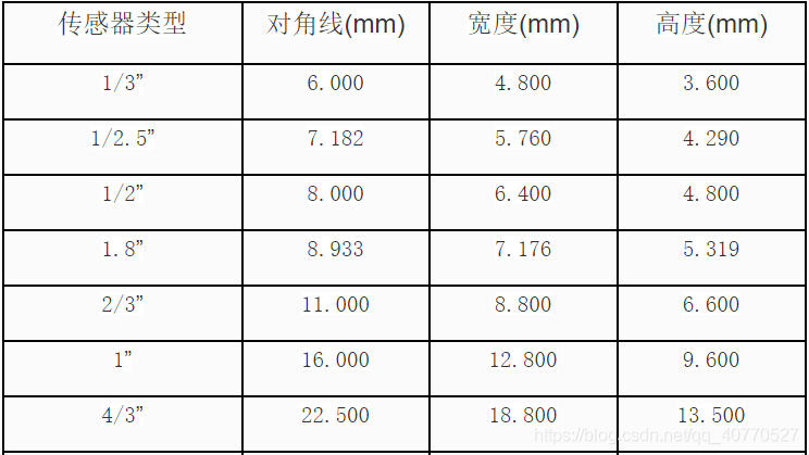
Target surface size = diagonal size
Target area = sensor width x sensor height
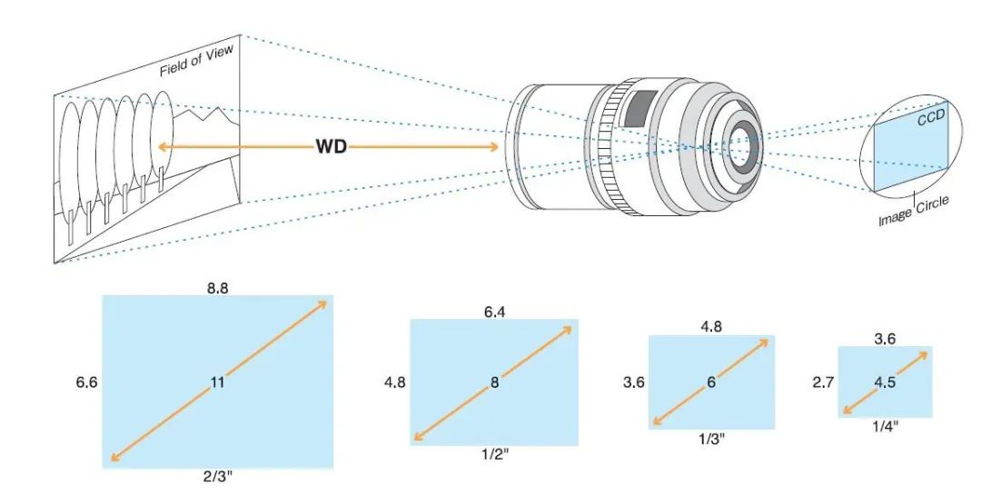
A larger sensor size means larger pixel sizes for the same pixel density, increasing the light-sensitive area of each pixel and thus improving image quality. Sensor size also determines the field of view and working distance. At the same working distance and with the same lens, a larger sensor size allows for a wider field of view.
(5) Pixel size
With the camera resolution and sensor size, the pixel size can be calculated.
Pixel size = Sensor size / Resolution (number of pixels)
This will give us the pixel dimensions for both width and height.
Pixel size refers to the actual physical size of each pixel in a chip's pixel array, such as 3.75µm x 3.75µm. Pixel size reflects, to some extent, the chip's light response capability; the larger the pixel size, the more photons it can receive, and the more charge it generates under the same lighting conditions and exposure time. For low-light imaging, pixel size is a characterization of chip sensitivity. This might sound confusing, as it resembles camera resolution, where a smaller resolution value indicates higher resolution. Here, a larger pixel size indicates higher sensitivity. However, these are two different concepts.
(6) Precision
Precision refers to the size of an actual object represented by one pixel, expressed as (um*um)/pixel. Note that pixel size is not equal to precision. Pixel size is fixed by the camera's mechanical structure, while precision is related to the camera's field of view and varies. The smaller the precision value, the higher the precision.
The size of a single pixel = field of view width / width resolution = field of view height / height resolution
(7) Image resolution
Image resolution is relatively easy to understand; it refers to how many pixels are used to display an image per unit distance. It has the same meaning as precision, only the method of representation is different.
2.Basic principles of selection
When the field of view (FOV) is constant (the size of the target being detected is generally considered the FOV when selecting a camera), a higher camera resolution results in higher accuracy and a larger image resolution. When the FOV is uncertain, cameras with different resolutions can achieve the same accuracy. In this case, choosing a camera with a large pixel count can expand the FOV, reduce the number of shots, and increase testing speed. If one camera has 1 megapixel resolution and another has 3 megapixels, and the clarity is the same (20µm/pixel), the FOV of the first camera is 20mm × 20mm = 400 square millimeters, while the FOV of the second camera is 1200 square millimeters. When photographing the same number of targets on a production line, assuming the first camera needs to take 30 images, the second camera only needs to take 10 images.


 Ms.Cici
 8618319014500