
Using FIRE's Spotlight Database - spotlight red
To understand this process, refer to the illustration on the right. It is absolutely identical to the earlier illustration even though the circularly polarized light at the top is now considered to be approaching the polarizer from the left. One can observe from the illustration that the leftward horizontal (as observed looking along the direction of travel) component is leading the vertical component and that when the horizontal component is retarded by one quarter of a wavelength it will be transformed into the linearly polarized light illustrated at the bottom and it will pass through the linear polarizer.
202253 — The standard technique is the 3-point setup. This consists of the main light source (the key light) along with the fill light and backlight.
One of the simplest linear polarizers is the wire-grid polarizer (WGP), which consists of many fine parallel metallic wires placed in a plane. WGPs mostly reflect the non-transmitted polarization and can thus be used as polarizing beam splitters. The parasitic absorption is relatively high compared to most of the dielectric polarizers though much lower than in absorptive polarizers.
Advanced illumination, Inc. is a lighting solutions company, designing and manufacturing a broad range of LED lights.
Circular polarizers can also be used to selectively absorb or pass right-handed or left-handed circularly polarized light. It is this feature which is utilized by the 3D glasses in stereoscopic cinemas such as RealD Cinema. A given polarizer which creates one of the two polarizations of light will pass that same polarization of light when that light is sent through it in the other direction. In contrast it will block light of the opposite polarization.
We use Malus's law for one polarizer at a time and get the intensities. We need to work oiut angles between successive polarizers at instant \(t\text{.}\) Let us choose time \(t=0\) to be the instant when the rotating polarizer is aligned with the first fixed polarizer. Then, angle in which the rotating polarizer will be pointed with respect to the first polarizer will be
Unpolarizedlight
A polarizer or polariser is an optical filter that lets light waves of a specific polarization pass through while blocking light waves of other polarizations.[1][2][3][4] It can filter a beam of light of undefined or mixed polarization into a beam of well-defined polarization, known as polarized light. Polarizers are used in many optical techniques and instruments. Polarizers find applications in photography and LCD technology. In photography, a polarizing filter can be used to filter out reflections.
Beam-splitting polarizers split the incident beam into two beams of differing linear polarization. For an ideal polarizing beamsplitter these would be fully polarized, with orthogonal polarizations. For many common beam-splitting polarizers, however, only one of the two output beams is fully polarized. The other contains a mixture of polarization states.
Finally, if the direction of polarization of incident light is some angle \(\theta\) to the the polarization direction of the polarizer, then only some of the light is blocked. How much is blocked in this case? To analyze this general case, note that we need to think in terms of electric field to see what is let through and what is blocked.
A homogeneous circular polarizer passes one handedness of circular polarization unaltered and blocks the other handedness. This is similar to the way that a linear polarizer would fully pass one angle of linearly polarized light unaltered, but would fully block any linearly polarized light that was orthogonal to it.
Linear polarization
There are some naturally occuring crystals, such as tourmaline, that have dichroic property of preferentially absorbing polarization light. Hence, such a crystal will let through light polarized in the perpendicular direction to the direction of polarization that the crystal absorbs. These crystals introduce some other artefacts such as absorption depending on wavelength also and they are not the primary means we obtain polarized light.
This is called Malus's law. How can we test this law? We setup an experiment that produces a linearly polarized light with a known direction of polarization, which is then passed through an identical polarizer whose preferred axis makes an angle \(\theta\) with respect to the polarization direction of the polarized light as shown in Figure 49.5.4. In this setup we calle the first polarizer a polarizer and call the second polarizer an analyzer.
A Polaroid polarizing filter functions similarly on an atomic scale to the wire-grid polarizer. It was originally made of microscopic herapathite crystals. Its current H-sheet form is made from polyvinyl alcohol (PVA) plastic with an iodine doping. Stretching of the sheet during manufacture causes the PVA chains to align in one particular direction. Valence electrons from the iodine dopant are able to move linearly along the polymer chains, but not transverse to them. So incident light polarized parallel to the chains is absorbed by the sheet; light polarized perpendicularly to the chains is transmitted. The durability and practicality of Polaroid makes it the most common type of polarizer in use, for example for sunglasses, photographic filters, and liquid crystal displays. It is also much cheaper than other types of polarizer.
Key Benefits of a Light Meter and a LUX Meter: Portable and sometimes pocket-sized, they are a useful piece of equipment to have for any light measuring ...
In trying to appreciate how the quarter-wave plate transforms the linearly polarized light, it is important to realize that the two components discussed are not entities in and of themselves but are merely mental constructs one uses to help appreciate what is happening. In the case of linearly and circularly polarized light, at each point in space, there is always a single electric field with a distinct vector direction, the quarter-wave plate merely has the effect of transforming this single electric field.
Certain crystals, due to the effects described by crystal optics, show dichroism, preferential absorption of light which is polarized in particular directions. They can therefore be used as linear polarizers. The best known crystal of this type is tourmaline. However, this crystal is seldom used as a polarizer, since the dichroic effect is strongly wavelength dependent and the crystal appears coloured. Herapathite is also dichroic, and is not strongly coloured, but is difficult to grow in large crystals.
A Nicol prism was an early type of birefringent polarizer, that consists of a crystal of calcite which has been split and rejoined with Canada balsam. The crystal is cut such that the o- and e-rays are in orthogonal linear polarization states. Total internal reflection of the o-ray occurs at the balsam interface, since it experiences a larger refractive index in calcite than in the balsam, and the ray is deflected to the side of the crystal. The e-ray, which sees a smaller refractive index in the calcite, is transmitted through the interface without deflection. Nicol prisms produce a very high purity of polarized light, and were extensively used in microscopy, though in modern use they have been mostly replaced with alternatives such as the Glan–Thompson prism, Glan–Foucault prism, and Glan–Taylor prism. These prisms are not true polarizing beamsplitters since only the transmitted beam is fully polarized.
polarization极化
Analytical solutions using rigorous coupled-wave analysis for wire grid polarizers have shown that for electric field components perpendicular to the wires, the medium behaves like a dielectric, and for electric field components parallel to the wires, the medium behaves like a metal (reflective).[9]
We use Malus's law for one polarizer at a time and get the intensities. The angles between the electric field direction of the incident wave and the polarizer in these cases are \(30^\circ\text{,}\) \(60^\circ\text{,}\) and \(30^\circ\text{,}\) respectively.
In Section 49.4, we have also seen that if we reflect light at Brewster's angle, then P-wave does not have any reflection but S-wave does have reflection. Therefore, if we reflect an unpolarized light off a surface at the Brewster's angle, then we will get only S-wave in the reflected direction. Now, S-wave is polarized perpendicular to the plane of incidence. This will give light polarized linearly in the direction perpendicular to the incidence plane and parallel to the interface.
Thin-film linear polarizers (also known as TFPN) are glass substrates on which a special optical coating is applied. Either Brewster's angle reflections or interference effects in the film cause them to act as beam-splitting polarizers. The substrate for the film can either be a plate, which is inserted into the beam at a particular angle, or a wedge of glass that is cemented to a second wedge to form a cube with the film cutting diagonally across the center (one form of this is the very common MacNeille cube[7]). Thin-film polarizers generally do not perform as well as Glan-type polarizers, but they are inexpensive and provide two beams that are about equally well polarized. The cube-type polarizers generally perform better than the plate polarizers. The former are easily confused with Glan-type birefringent polarizers.
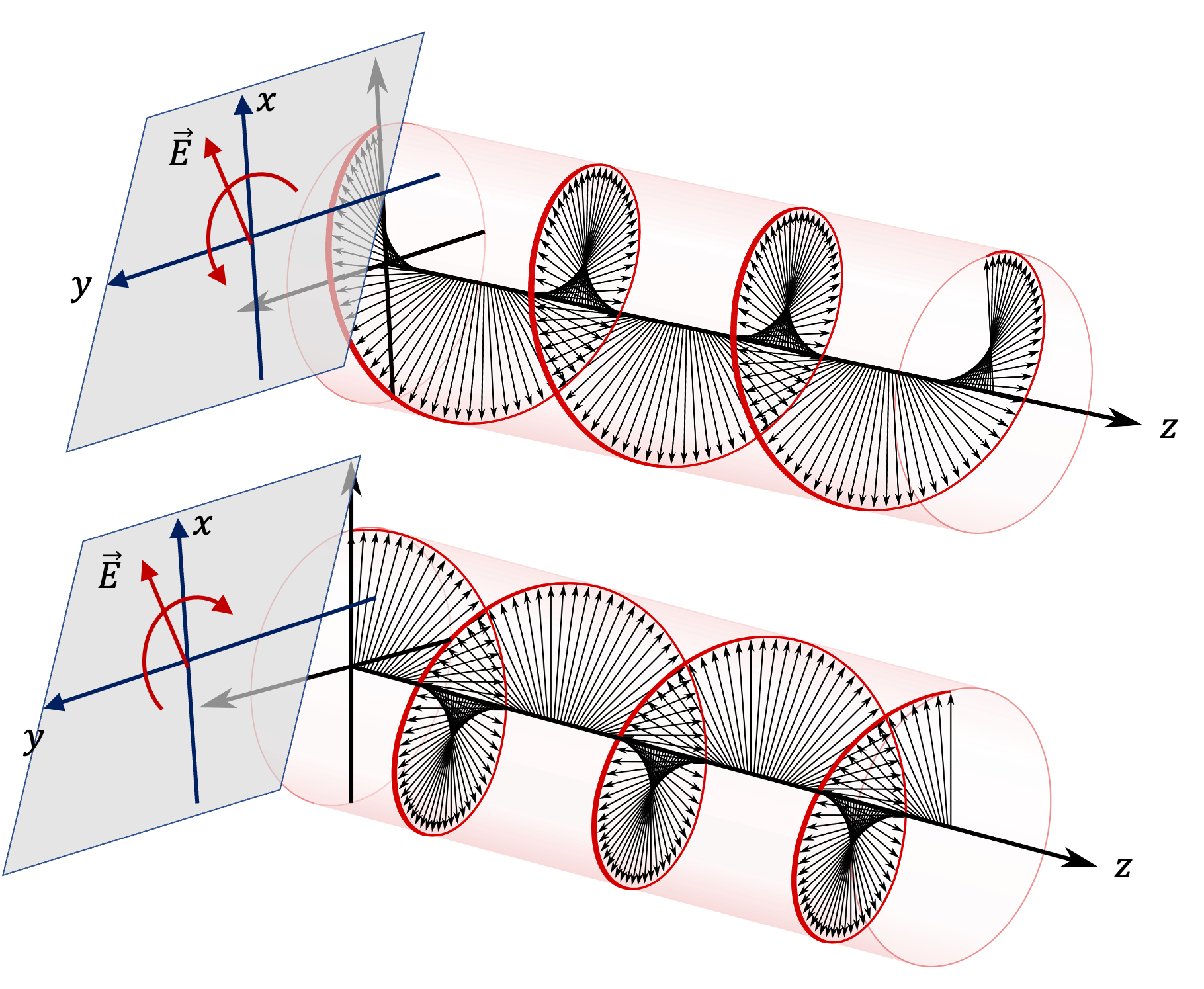
Another polarization of particular interest happens when electric field direction rotates in space and time as shown in Figure 49.5.2. For a wave traveling towards positive \(z\) axis, electric field direction will be in the \(xy\) plane. For linear polarized light, the electric field stays along one line in \(xy\) plane. But, if light is circularly polarized, the direction of polarization rotates in \(xy\) plane as shown in the figure.
In the arrangement above, the transmission axis of the linear polarizer is at a positive 45° angle relative to the right horizontal and is represented with an orange line. The quarter-wave plate has a horizontal slow axis and a vertical fast axis and they are also represented using orange lines. In this instance the unpolarized light entering the linear polarizer is displayed as a single wave whose amplitude and angle of linear polarization are suddenly changing.
You can see these expressions by looking at the plane at \(z=0\) and nting that \(\omega=2\pi/T\) where \(T\) is one period. In a quarter cycle, the electric field will go from pointing towards positive \(x\) axis to positive \(y\) axis.
Unlike absorptive polarizers, beam splitting polarizers do not need to absorb and dissipate the energy of the rejected polarization state, and so they are more suitable for use with high intensity beams such as laser light. True polarizing beamsplitters are also useful where the two polarization components are to be analyzed or used simultaneously.
A prism is a transparent optical element with flat, polished surfaces that refract light. The most common type of prism is a triangular prism, ...
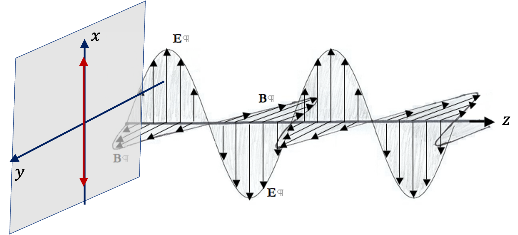
A simple polarized wave will have electric field just oscillating back and forth along some fixed line. This light is said to be linearly polarized light. For instance, if an electromagnetic wave is moving in the direction of positive \(z\) axis in vacuum and its electric field at any point is pointed either towards positive or negative \(x\) axis as illustrated in Figure 49.5.1. Then, we say that the wave is linearly polarized in the \(x\) direction. Suppose the wave has wavenumber \(k\) and angular frequency \(\omega\text{.}\) Then, we can represent this wave with amplitude \(E_0\) as
Plot the following time-varying vectors in \(xy\) plane at \(t = 0\text{,}\) \(0.2\text{,}\) \(0.4\text{,}\) \(0.6\text{,}\) and \(0.8\) in units of the period of the cosine or sine functions given. State the direction of rotation of the electric field vectors when observed from the positive \(z\) axis. Here unit vectors in the Cartesian \(x\) and \(y\) are denoted by \(\hat u_x\) and \(\hat u_y\) respectively.
Overall, this causes the transmitted wave to be linearly polarized with an electric field completely perpendicular to the wires. The hypothesis that the waves "slip through" the gaps between the wires is incorrect.[8]
The illustration above is identical to the previous similar one with the exception that the left-handed circularly polarized light is now approaching the polarizer from the opposite direction and linearly polarized light is exiting the polarizer toward the right.
Generally speaking, and not making direct reference to the above illustration, when either of the two polarizations of circularly polarized light enters the first quarter-wave plate, one of a pair of orthogonal components is retarded by one quarter of a wavelength relative to the other. This creates one of two linear polarizations depending on the handedness the circularly polarized light. The linear polarizer sandwiched between the quarter wave plates is oriented so that it will pass one linear polarization and block the other. The second quarter-wave plate then takes the linearly polarized light that passes and retards the orthogonal component that was not retarded by the previous quarter-wave plate. This brings the two components back into their initial phase relationship, reestablishing the selected circular polarization.
Malus' law (/məˈluːs/), which is named after Étienne-Louis Malus, says that when a perfect polarizer is placed in a polarized beam of light, the irradiance, I, of the light that passes through is given by
When one attempts to pass unpolarized light through the linear polarizer, only light that has its electric field at the positive 45° angle leaves the linear polarizer and enters the quarter-wave plate. In the illustration, the three wavelengths of unpolarized light represented would be transformed into the three wavelengths of linearly polarized light on the other side of the linear polarizer.
If you shine a linearly polarized light on a linear polarizer with direction of polarization of light same as the the polarization direction of the polarizer, then all of the incident light is trnasmitted through the polarizer. On the other hand, if the direction of polarization of incident light perpendicular to the the polarization direction of the polarizer, then all light is blocked.
In the instance just cited, using the handedness convention used in many optics textbooks, the light is considered left-handed/counter-clockwise circularly polarized. Referring to the accompanying animation, it is considered left-handed because if one points one's left thumb against the direction of travel, ones fingers curl in the direction the electric field rotates as the wave passes a given point in space. The helix also forms a left-handed helix in space. Similarly this light is considered counter-clockwise circularly polarized because if a stationary observer faces against the direction of travel, the person will observe its electric field rotate in the counter-clockwise direction as the wave passes a given point in space.[11]
For practical purposes, the separation between wires must be less than the wavelength of the incident radiation. In addition, the width of each wire should be small compared to the spacing between wires. Therefore, it is relatively easy to construct wire-grid polarizers for microwaves, far-infrared, and mid-infrared radiation. For far-infrared optics, the polarizer can be even made as free standing mesh, entirely without transmissive optics. In addition, advanced lithographic techniques can also build very tight pitch metallic grids (typ. 50‒100 nm), allowing for the polarization of visible or infrared light to a useful degree. Since the degree of polarization depends little on wavelength and angle of incidence, they are used for broad-band applications such as projection.
For waves with electric fields perpendicular to the wires, the electrons cannot move very far across the width of each wire. Therefore, little energy is reflected and the incident wave is able to pass through the grid. In this case the grid behaves like a dielectric material.
Real polarizers are also not perfect blockers of the polarization orthogonal to their polarization axis; the ratio of the transmission of the unwanted component to the wanted component is called the extinction ratio, and varies from around 1:500 for Polaroid to about 1:106 for Glan–Taylor prism polarizers.
There are various types of polarizers depending on the polarization of the light that is emitted from the polarizer. For instance, if light emitted is linearly polarized, we call it a linear polarizer and light emitted is a circularly polarized light we call it a circular polarizer. Linear polarizers are easier to understand and we will mstly look at them.
Dec 20, 2023 — A light guide is a transparent material that allows the light from a light source to enter and travel through the material.
The above describes how you can turn a linearly polarized light into a circularly polarized light. If you want to go the other way around, it is much simpler - you just pass the circularly polarized light through a linear polarizer!
Circular polarization
(a) Function \(\cos(2\pi t)\) has period \(T\) equal to \(1\text{.}\) Therefore, first we compute values of \(\cos(2\pi t)\) at the instants \(t = 0\text{,}\) \(0.2\text{,}\) \(0.4\text{,}\) \(0.6\text{,}\) and \(0.8\text{.}\) Then we draw arrows along \(x\) axis since the direction is always aling \(x\) axis. For negative values, the arrow is pointed towards negative axis.
Circular polarizers (CPL or circular polarizing filters) can be used to create circularly polarized light or alternatively to selectively absorb or pass clockwise and counter-clockwise circularly polarized light. They are used as polarizing filters in photography to reduce oblique reflections from non-metallic surfaces, and are the lenses of the 3D glasses worn for viewing some stereoscopic movies (notably, the RealD 3D variety), where the polarization of light is used to differentiate which image should be seen by the left and right eye.
At the top of the illustration toward the right is the circularly polarized light after it leaves the wave plate. Directly below it, for comparison purposes, is the linearly polarized light that entered the quarter-wave plate. In the upper image, because this is a plane wave, each vector leading from the axis to the helix represents the magnitude and direction of the electric field for an entire plane that is perpendicular to the direction of travel. All the electric field vectors have the same magnitude indicating that the strength of the electric field does not change. The direction of the electric field however steadily rotates.
Because their polarization vectors depend on incidence angle, polarizers based on Fresnel reflection inherently tend to produce s–p polarization rather than Cartesian polarization,[clarification needed] which limits their use in some applications.
A simple linear polarizer can be made by tilting a stack of glass plates at Brewster's angle to the beam. Some of the s-polarized light is reflected from each surface of each plate. For a stack of plates, each reflection depletes the incident beam of s-polarized light, leaving a greater fraction of p-polarized light in the transmitted beam at each stage. For visible light in air and typical glass, Brewster's angle is about 57°, and about 16% of the s-polarized light present in the beam is reflected for each air-to-glass or glass-to-air transition. It takes many plates to achieve even mediocre polarization of the transmitted beam with this approach. For a stack of 10 plates (20 reflections), about 3% (= (1 − 0.16)20) of the s-polarized light is transmitted. The reflected beam, while fully polarized, is spread out and may not be very useful.
Now, since the second fixed polarizer has the same orientation as the first fixed polarizer, angle between the electric field of the wave incident on the second fixed polarizer will also be \(2\pi f t\text{.}\) Therefore, the intensity after the second fixed polarizer will be
(a) Compute \(\cos(2\pi t)\) at \(t = 0\text{,}\) \(0.2\text{,}\) \(0.4\text{,}\) \(0.6\text{,}\) and \(0.8\) (b) Similar to (a), but now you add two vectors to get the net vector.
Light and all other electromagnetic waves have a magnetic field which is in phase with, and perpendicular to, the electric field being displayed in these illustrations.
Because the quarter-wave plate is made of a birefringent material, when in the wave plate, the light travels at different speeds depending on the direction of its electric field. This means that the horizontal component which is along the slow axis of the wave plate will travel at a slower speed than the component that is directed along the vertical fast axis. Initially the two components are in phase, but as the two components travel through the wave plate the horizontal component of the light drifts farther behind that of the vertical. By adjusting the thickness of the wave plate one can control how much the horizontal component is delayed relative to vertical component before the light leaves the wave plate and they begin again to travel at the same speed. When the light leaves the quarter-wave plate the rightward horizontal component will be exactly one quarter of a wavelength behind the vertical component making the light left-hand circularly polarized when viewed from the receiver.[11]
Natural light such as the light from the Sun is unpolarized. It is generally a random mixture of various waves of different polarizations and frequencies. There are devices that act as filter of light and let through light with a particular type of polarization. These devices are called polarizers.
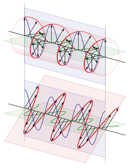
Looking at \(E_x\) and \(E_y\text{,}\) you would notice that if the arguments of the cosines, i.e., the phases, of \(E_x\) and \(E_y\) were same, you would not get any rotation. The rotation of electric field, which is a vector sum of the \(x\) and \(y\) parts, comes from the lag of phase of the \(E_y\) wave, the full value of \(E_y\) occurs \(T/4\) later than it occurs for \(E_x\text{.}\)
Using this knowledge, we can immediately write the expressions fro \(E_x\) and \(E_y\) for left-circularly polarized light by just changing the sign of the phase constant in \(E_y\text{.}\)
Jun 7, 2021 — Filmmakers on a budget can use inexpensive household items make some film lighting equipment, such as a light diffuser.
more uniform light distribution when lit from the side by LEDs. • up to 30% higher luminous efficiency, depending on the chosen structure, as compared with ...
To create a circular polarizer that instead passes right-handed polarized light and absorbs left-handed light, one again rotates the wave plate and linear polarizer 90° relative to each another. It is easy to appreciate that by reversing the positions of the transmitting and absorbing axes of the linear polarizer relative to the quarter-wave plate, one changes which handedness of polarized light gets transmitted and which gets absorbed.
To understand the effect the quarter-wave plate has on the linearly polarized light it is useful to think of the light as being divided into two components which are at right angles (orthogonal) to each other. Towards this end, the blue and green lines are projections of the red line onto the vertical and horizontal planes respectively and represent how the electric field changes in the direction of those two planes. The two components have the same amplitude and are in phase.
Other linear polarizers exploit the birefringent properties of crystals such as quartz and calcite. In these crystals, a beam of unpolarized light incident on their surface is split by refraction into two rays. Snell's law holds for both of these rays, the ordinary or o-ray, and the extraordinary or e-ray, with each ray experiencing a different index of refraction (this is called double refraction). In general the two rays will be in different polarization states, though not in linear polarization states except for certain propagation directions relative to the crystal axis.
where I0 is the initial intensity and θi is the angle between the light's initial polarization direction and the axis of the polarizer.
Often we describe a circularly polarized light by stating its component electric fields. For instance, for right-circularly polarized light moving in the direction of \(z\) axis of Figure 49.5.2, we can give \(E_x\) and \(E_y\) wave functions.
where \(\hat u_x\) is a unit vector in the direction of positive \(x\) axis, usually denoted by \(\hat i\) also. The line of polarization for a linearly polarized light remains fixed in time although the direction of electric field varies since it oscillates back anf forth along the line.
Polarization oflight
There is a relatively straightforward way to appreciate why a polarizer which creates a given handedness of circularly polarized light also passes that same handedness of polarized light. First, given the dual usefulness of this image, begin by imagining the circularly polarized light displayed at the top as still leaving the quarter-wave plate and traveling toward the left. Observe that had the horizontal component of the linearly polarized light been retarded by a quarter of wavelength twice, which would amount to a full half wavelength, the result would have been linearly polarized light that was at a right angle to the light that entered. If such orthogonally polarized light were rotated on the horizontal plane and directed back through the linear polarizer section of the circular polarizer it would clearly pass through given its orientation. Now imagine the circularly polarized light which has already passed through the quarter-wave plate once, turned around and directed back toward the circular polarizer again. Let the circularly polarized light illustrated at the top now represent that light. Such light is going to travel through the quarter-wave plate a second time before reaching the linear polarizer and in the process, its horizontal component is going to be retarded a second time by one quarter of a wavelength. Whether that horizontal component is retarded by one quarter of a wavelength in two distinct steps or retarded a full half wavelength all at once, the orientation of the resulting linearly polarized light will be such that it passes through the linear polarizer.
When light reflects (by Fresnel reflection) at an angle from an interface between two transparent materials, the reflectivity is different for light polarized in the plane of incidence and light polarized perpendicular to it. Light polarized in the plane is said to be p-polarized, while that polarized perpendicular to it is s-polarized. At a special angle known as Brewster's angle, no p-polarized light is reflected from the surface, thus all reflected light must be s-polarized, with an electric field perpendicular to the plane of incidence.
A homogeneous circular polarizer can be created by sandwiching a linear polarizer between two quarter-wave plates.[12] Specifically we take the circular polarizer described previously, which transforms circularly polarized light into linear polarized light, and add to it a second quarter-wave plate rotated 90° relative to the first one.
Large Magnifying Glass With Light,10X 20X Large Magnifier Handheld Illuminate... By Buy Bye. Magnifying Glass With Light, ...
First note that a quarter-wave plate always transforms circularly polarized light into linearly polarized light. It is only the resulting angle of polarization of the linearly polarized light that is determined by the orientation of the fast and slow axes of the quarter-wave plate and the handedness of the circularly polarized light. In the illustration, the left-handed circularly polarized light entering the polarizer is transformed into linearly polarized light which has its direction of polarization along the transmission axis of the linear polarizer and it therefore passes. In contrast right-handed circularly polarized light would have been transformed into linearly polarized light that had its direction of polarization along the absorbing axis of the linear polarizer, which is at right angles to the transmission axis, and it would have therefore been blocked.
polarization中文
There are several ways to create circularly polarized light, the cheapest and most common involves placing a quarter-wave plate after a linear polarizer and directing unpolarized light through the linear polarizer. The linearly polarized light leaving the linear polarizer is transformed into circularly polarized light by the quarter wave plate. The transmission axis of the linear polarizer needs to be half way (45°) between the fast and slow axes of the quarter-wave plate.
Linear polarizing filters were the first types to be used in photography and can still be used for non-reflex and older single-lens reflex cameras (SLRs). However, cameras with through-the-lens metering (TTL) and autofocusing systems – that is, all modern SLR and DSLR – rely on optical elements that pass linearly polarized light. If light entering the camera is already linearly polarized, it can upset the exposure or autofocus systems. Circular polarizing filters cut out linearly polarized light and so can be used to darken skies, improve saturation and remove reflections, but the circular polarized light it passes does not impair through-the-lens systems.[13]
Had it been right-handed, clockwise circularly polarized light approaching the circular polarizer from the left, its horizontal component would have also been retarded, however the resulting linearly polarized light would have been polarized along the absorbing axis of the linear polarizer and it would not have passed.
Electromagnetic waves that have a component of their electric fields aligned parallel to the wires will induce the movement of electrons along the length of the wires. Since the electrons are free to move in this direction, the polarizer behaves in a similar manner to the surface of a metal when reflecting light, and the wave is reflected backwards along the incident beam (minus a small amount of energy lost to Joule heating of the wire).[8]
Jul 24, 2022 — noun Light in which electromagnetic vibrations oscillate repeatedly in only one direction perpendicular to the direction of propagation.
There are two types of circularly polarized light as shown in Figure 49.5.2. One way to tell the difference is to use handedness. Point the thumb of your right towards the direction of propagation of the wave. Now, if you curl the other fingers and the electric field rotates in time in the same direction as curling of your other fingers of your right hand, then it is said to be right-handed circularly polarized and if it goes in the opposite direction, then you have left-handed circularly polarized. Sometimes clockwise and countecloskwise is also used, but they depend on whether you are looking from the direction of the source or the target.
A modern type of absorptive polarizer is made of elongated silver nano-particles embedded in thin (≤0.5 mm) glass plates. These polarizers are more durable, and can polarize light much better than plastic Polaroid film, achieving polarization ratios as high as 100,000:1 and absorption of correctly polarized light as low as 1.5%.[5] Such glass polarizers perform best for long-wavelength infrared light, and are widely used in fiber-optic communication.
We will discuss special types of crystals, such as calcite, that have refractive index that depends on the polarization direction of light with respect to a crystal axis. These crystals are called birefringent crystals This leads to separation of light of different polarizations and hence can also be used to produce polarized light.
The blue and green lines are projections of the helix onto the vertical and horizontal planes respectively and represent how the electric field changes in the direction of those two planes. Notice how the rightward horizontal component is now one quarter of a wavelength behind the vertical component. It is this quarter of a wavelength phase shift that results in the rotational nature of the electric field. When the magnitude of one component is at a maximum the magnitude of the other component is always zero. This is the reason that there are helix vectors which exactly correspond to the maxima of the two components.
A more useful polarized beam can be obtained by tilting the pile of plates at a steeper angle to the incident beam. Counterintuitively, using incident angles greater than Brewster's angle yields a higher degree of polarization of the transmitted beam, at the expense of decreased overall transmission. For angles of incidence steeper than 80° the polarization of the transmitted beam can approach 100% with as few as four plates, although the transmitted intensity is very low in this case.[6] Adding more plates and reducing the angle allows a better compromise between transmission and polarization to be achieved.
In practice, some light is lost in the polarizer and the actual transmission will be somewhat lower than this, around 38% for Polaroid-type polarizers but considerably higher (>49.9%) for some birefringent prism types.
A Wollaston prism is another birefringent polarizer consisting of two triangular calcite prisms with orthogonal crystal axes that are cemented together. At the internal interface, an unpolarized beam splits into two linearly polarized rays which leave the prism at a divergence angle of 15°–45°. The Rochon and Sénarmont prisms are similar, but use different optical axis orientations in the two prisms. The Sénarmont prism is air spaced, unlike the Wollaston and Rochon prisms. These prisms truly split the beam into two fully polarized beams with perpendicular polarizations. The Nomarski prism is a variant of the Wollaston prism, which is widely used in differential interference contrast microscopy.
In general, the direction of electric field in the electromagnetic wave is called the polarization direction of light. A light source may be producing very large number of waves, each of which has electric field in a random direction. This light will not be polarized. We call such light \(unpolarized\text{.}\)
Circularly polarizedlight
In Section 49.4 we saw important role of the direction of the electric field in determining how much of an electromagnetic wave will be reflected or transmitted when light is incident. A S-polarized wave (also known as transverse electric or TE) behaves differently than a P-polarized wave (also know as transverse magnetic or TM). That was one example of role of direction of electric field.
(b) Function \(\cos(2\pi t)\) as well as \(\sin(2\pi t)\) has period \(T\) equal to \(1\text{.}\) Therefore, first we compute values of \(\cos(2\pi t)\) and \(\sin(2\pi t)\) at the instants \(t = 0\text{,}\) \(0.2\text{,}\) \(0.4\text{,}\) \(0.6\text{,}\) and \(0.8\text{.}\) Then we draw vector arrows at these instants. We see that this is right-circularly polarized wave if the wave is coming out of page and the vector given is at \(z=0\) or some other constant \(z\) plane.
The common types of polarizers are linear polarizers and circular polarizers. Polarizers can also be made for other types of electromagnetic waves besides visible light, such as radio waves, microwaves, and X-rays.
A majority of polarizers, such as use in sun glasses, are made from synthetic materials. For instance, in H-sheet Polaroid, clear polyvinyl alcohol (PVA) is stretched along its chains, and then dipped into iodine solution which imbeds into the plastic and arranges along the long hydrocarbon chains, essentially making molecular size wires of iodine. These Polaroids transmit electromagnetic waves whose polarization is perpendicular to the direction of "iodine wires". In a sense, these are synthetic dichroic materials, and that is why ther are also referred to as dichroic filters.
Figure 49.5.9 shows a setup in which a linear polarizer is rotated between two identical stationary crossed polarizers. Find the intensity of the emerging wave in terms of the intensity \(I_0\) of the light after the first fixed polarizer and the frequency \(f\) of rotation of the rotating polarizer.
Linear polarizers can be divided into two general categories: absorptive polarizers, where the unwanted polarization states are absorbed by the device, and beam-splitting polarizers, where the unpolarized beam is split into two beams with opposite polarization states. Polarizers which maintain the same axes of polarization with varying angles of incidence[clarification needed] are often called[citation needed] Cartesian polarizers, since the polarization vectors can be described with simple Cartesian coordinates (for example, horizontal vs. vertical) independent from the orientation of the polarizer surface. When the two polarization states are relative to the direction of a surface (usually found with Fresnel reflection), they are usually termed s and p. This distinction between Cartesian and s–p polarization can be negligible in many cases, but it becomes significant for achieving high contrast and with wide angular spreads of the incident light.
To create right-handed, clockwise circularly polarized light one simply rotates the axis of the quarter-wave plate 90° relative to the linear polarizer. This reverses the fast and slow axes of the wave plate relative to the transmission axis of the linear polarizer reversing which component leads and which component lags.
where f 0 {\displaystyle f_{0}} – frequency of the polarized radiation falling on the polarizer, f {\displaystyle f} – frequency of the radiation passes through polarizer, λ {\displaystyle \lambda } – Compton wavelength of electron, c {\displaystyle c} – speed of light in vacuum.[10]
A linear polarizer lets through the component of the electric field that is parallel to the axis of the polarizer. Consider a linearly polarized EM wave moving towards positive \(z\) axis. Its polarization will be in the \(xy\) plane, say at an angle \(\theta\) from \(x\) axis. This means that the amplitude vector \(\vec E_0\) is in this direction. Suppose it is incident on a linear polarizer whose axis is along \(x\) axis. Then, the wave on the other side will have amplitude equal to the \(x\) component of \(\vec E_0\) and direction of \(x\) axis, which will be
In the illustration toward the right is the electric field of the linearly polarized light just before it enters the quarter-wave plate. The red line and associated field vectors represent how the magnitude and direction of the electric field varies along the direction of travel. For this plane electromagnetic wave, each vector represents the magnitude and direction of the electric field for an entire plane that is perpendicular to the direction of travel. (Refer to these two images in the plane wave article to better appreciate this.)
Electric polarization
If two polarizers are placed one after another (the second polarizer is generally called an analyzer), the mutual angle between their polarizing axes gives the value of θ in Malus's law. If the two axes are orthogonal, the polarizers are crossed and in theory no light is transmitted, though again practically speaking no polarizer is perfect and the transmission is not exactly zero (for example, crossed Polaroid sheets appear slightly blue in colour because their extinction ratio is better in the red). If a transparent object is placed between the crossed polarizers, any polarization effects present in the sample (such as birefringence) will be shown as an increase in transmission. This effect is used in polarimetry to measure the optical activity of a sample.
A retarder is constructed to retard the phase of one of the components by a set amount. You can buy full-wave, half-wave and quarter-wave plates. The cause relative retardations of the phase by \(2\pi\text{ rad}\text{,}\) \(\pi\text{ rad}\) and \(\pi/2\text{ rad}\) respectively. Also commonly available are compensators which can be used to produce retardation to a arbitrary degree.
VEVOR Magnifying Glass with Light and Stand, 5X Magnifying Lamp, 4.3 in. Glass Lens, Base and Clamp 2-in-1 Desk Magnifier
By using an appropriate arrangement of linear polarizers, you can obtain polarized light that is polarized in any desired direction in the plane perpendicular to the direction of the wave. However, each polarizer reduces the intensity of light by blocking off the perpendicular components.
The wave is passed through a linear polarizer whose polarizing axis is pointed \(45^\circ\) counterclockwise to the \(x\) axis. Find the intensity of the emergent wave in terms of the intensity of the incident wave.
If you look back in Subsection 49.5.2, you will find that to produce right circularly polarized light moving in positive \(z\) axis, we need to introduce delay of \(\pi/2\) in the phase of the \(E_y\) wave relative to the \(E_x\) wave. And similarly for the left-circularly polarized light. Thus, we need polarization dependent wave velocity. Recall that wave velocity in a medium is \(v = c/n\text{.}\) This means we need polarization dependent refractive index. Birefringent materials have just such a property. Therefore, when a linearly polarized light is sent in appropriate direction and through appropriate thickness of a birefringent crystal, the crystal produces the desired delay. These devices are called retarders.
Use Malus's law for each polarizer. Note tha angle between the rotating polarizer and either of the two polarizers will be same.
A beam of unpolarized light can be thought of as containing a uniform mixture of linear polarizations at all possible angles. Since the average value of cos 2 θ {\displaystyle \cos ^{2}\theta } is 1/2, the transmission coefficient becomes


 Ms.Cici
 8618319014500