
Speed of light - light measure
Basler cameramanual
Driver OptionsThorlabs offers six drivers compatible with these LEDs: LEDD1B, UPLED, DC40, DC2200, DC4100, and DC4104 (the latter two require the DC4100-HUB). The UPLED, DC40, DC2200, DC4100, and DC4104 drivers are capable of reading the current limit from the EEPROM chip of the connected LED and automatically adjusting the maximum current setting to protect the LED. See the LED Drivers tab for specifications and comparison between the drivers.
The diagram to the right shows the male connector of the collimated LED assembly. It is a standard M8 x 1 sensor circular connector. Pins 1 and 2 are the connection to the LED. Pin 3 and 4 are used for the internal EEPROM in these LEDs. If using an LED driver that was not purchased from Thorlabs, be careful that the appropriate connections are made to Pin 1 and Pin 2 and that you do not attempt to drive the LED through the EEPROM pins.
basler中国
International Light Technologies Div. of Labsphere Inc. ... 10 Technology Dr. ... Manufactures light meters, radiometers, spectroradiometers, spectrophotometers, ...
© COPYRIGHT 2024 ILLUMINATION LIGHTING · ALL RIGHTS RESERVED. Contact Us. Name *. Email Address *. Phone Number. Where did you hear about us? *. Message *. 0 / ...
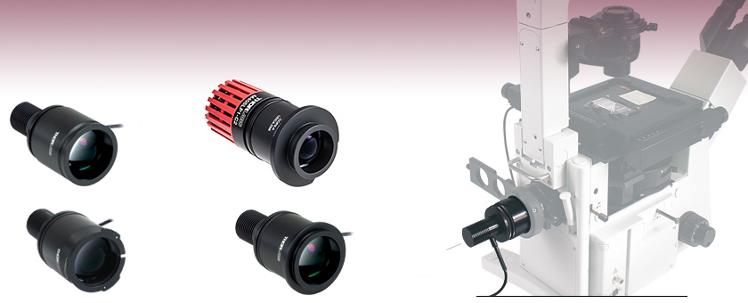
Note: Please ensure your microscope is configured to directly accept an external light source. Some microscope assemblies have a permanently installed illuminator or may be otherwise incompatible with the LED light sources below.
It is categorized as electromagnetic radiation with wavelengths between 10 and 400 nanometers (nm). Electromagnetic radiation consists of waves of electric and ...
Characteristics of Infrared Radiation · Infrared radiation consists of heat-inducing property. · The origin is from an alteration in electron movement.
Basler
This tab includes all LEDs sold by Thorlabs. Click on More [+] to view all available wavelengths for each type of LED pictured below.
2020114 — Infrared radiation extends from the nominal red edge of the visible spectrum at 700 nanometers (nm) to 1 millimeter (mm). This range of ...
Cognex
The UV-Sanitizer utilizes dual UV technology to kill viruses, bacteria, and germs on virtually any surface. The powerful combination of UVA and UVC lights kill ...
Baslerfrance
The section of the housing that holds the collimation optics is the same size for all LEDs that share the same item # suffix, regardless of the size of the heat sink.
For microscope applications requiring compatibility with SM1 (1.035"-40) threading, our mounted LEDs (sold separately) can be collimated using a Ø1" lens and lens tubes. This collimation method also allows for a smaller beam size than the collimators on this page. Please see the Collimation tab on our Mounted LEDs presentation for a detailed item list and instructions.
The approximate total beam power through the collimation adapter is given in the tables below and on the Specs tab. The actual power at the sample plane will be lower due to losses specific to the optical set up of the microscope. If you wish to measure the power at the sample plane for your particular microscope setup, Thorlabs also offers a microscope slide power meter sensor.
The CON8ML-4 connector can be used to mate mounted LEDs featured on this page to user-supplied power supplies. We also offer a male 4-Pin M8 connector cable (item # CAB-LEDD1).
Like our mounted LEDs, the package of these collimated LEDs is in direct contact with the heat sink to provide excellent thermal management. This minimizes the degradation of optical output power caused by increased LED temperatures. Please see the Stability tab for information on the stable output intensity of these collimated LEDs. Additionally, our M365LP1, M385LP1, and M405LP1 LEDs feature a higher power output and are mounted to a larger Ø57.0 mm heat sink to increase heat dissipation and thermal stability.
Thorlabs' collimated LED assemblies can be easily connected to standard and epi-illumination ports on most readily available commercial microscopes, including Olympus, Leica, Nikon, and Zeiss. Each collimated LED consists of a mounted LED and a lamphouse-port-compatible housing that contains an AR-coated aspheric collimation optic (see the Specs tab for details). If the wavelength or output power you require is not sold on this page, our mounted LEDs and Solis® High-Power LEDs are available in additional wavelengths and output powers.
Jun 7, 2021 — Filmmakers on a budget can use inexpensive household items make some film lighting equipment, such as a light diffuser.
basler工业相机
The thermal dissipation performance of these collimated LEDs has been optimized for stable power output. The heat sink is directly mounted to the LED mount so as to provide optimal thermal contact. By doing so, the degradation of optical output power that can be attributed to increased LED junction temperature is minimized (see the graph to the right).
Baslerace 2
Add ring light in people's eyes when taking portrait shooting. Ideal for 75W(600W Equivalent) ring light. Made of high light transmission nylon material with ...
Special grades of acrylic sheet, polycarbonate sheet, and polycarbonate film are engineered to diffuse LED hot spots without sacrificing light transmission.
Industrialcamera
The actual spectral output and total output power of any given LED will vary due to variations in the manufacturing process and operating parameters, such as temperature and current. The typical total beam power of each collimated LED is specified to help you select an LED that suits your needs. In order to provide a point of comparison for the relative powers of LEDs with different nominal wavelengths, the spectra in the plots below have been scaled to the typical total beam power of each collimated LED. This data is representative, not absolute. An Excel file containing the normalized and scaled spectra for each collimation package can be downloaded using the link below each plot.
One characteristic of LEDs is that they naturally exhibit power degradation with time. Often this power degradation is slow, but there are also instances where large, rapid drops in power, or even complete LED failure, occur. LED lifetimes are defined as the time it takes a specified percentage of a type of LED to fall below some power level. The parameters for the lifetime measurement can be written using the notation BXX/LYY, where XX is the percentage of that type of LED that will provide less than YY percent of the specified output power after the lifetime has elapsed. Thorlabs defines the lifetime of our LEDs as B50/L50, meaning that 50% of the LEDs with a given Item # will fall below 50% of the initial optical power at the end of the specified lifetime. For example, if a batch of 100 LEDs is rated for 150 mW of output power, 50 of these LEDs can be expected to produce an output power of ≤75 mW after the specified LED lifetime has elapsed.
The collimation of the beam can be adjusted by changing the position of the aspheric lens with respect to the LED. Interchanging LEDs is easy; simply unscrew one LED from the housing and replace it with a different mounted LED (sold separately). We also offer collimation packages, which can be purchased separately from these LEDs.
The section of the housing that holds the collimation optics is the same size for all LEDs that share the same item # suffix, regardless of the size of the heat sink.
Mar 2, 2021 — And it even works where the UV light cannot reach all the glue, since exposed glue will dry within a couple hours just like exposed super glue.
To fully support the max optical power of the LED you intend to drive, ensure that the max voltage and max current of the driver are equal to or greater than those of the LED.


 Ms.Cici
 8618319014500