
Could someone tell me what the industry standard ring ... - camera ring light
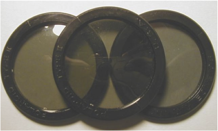
A majority of polarizers, such as use in sun glasses, are made from synthetic materials. For instance, in H-sheet Polaroid, clear polyvinyl alcohol (PVA) is stretched along its chains, and then dipped into iodine solution which imbeds into the plastic and arranges along the long hydrocarbon chains, essentially making molecular size wires of iodine. These Polaroids transmit electromagnetic waves whose polarization is perpendicular to the direction of "iodine wires". In a sense, these are synthetic dichroic materials, and that is why ther are also referred to as dichroic filters.
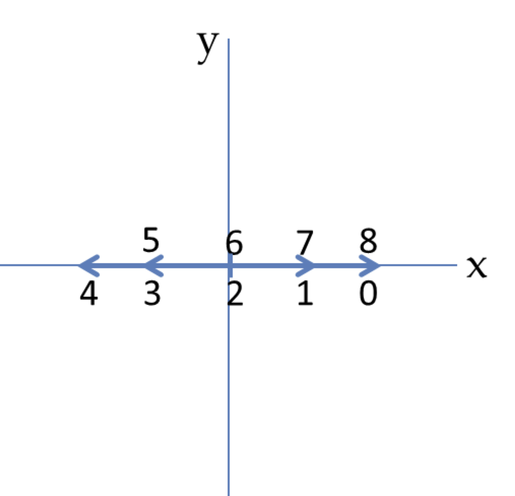
(a) Compute \(\cos(2\pi t)\) at \(t = 0\text{,}\) \(0.2\text{,}\) \(0.4\text{,}\) \(0.6\text{,}\) and \(0.8\) (b) Similar to (a), but now you add two vectors to get the net vector.
We will discuss special types of crystals, such as calcite, that have refractive index that depends on the polarization direction of light with respect to a crystal axis. These crystals are called birefringent crystals This leads to separation of light of different polarizations and hence can also be used to produce polarized light.
Now, since the second fixed polarizer has the same orientation as the first fixed polarizer, angle between the electric field of the wave incident on the second fixed polarizer will also be \(2\pi f t\text{.}\) Therefore, the intensity after the second fixed polarizer will be
By using an appropriate arrangement of linear polarizers, you can obtain polarized light that is polarized in any desired direction in the plane perpendicular to the direction of the wave. However, each polarizer reduces the intensity of light by blocking off the perpendicular components.
We have developed a series of acrylic bead light diffusers that when compounded into a polycarbonate bulb or tube produce a diffuse light with a high degree of ...
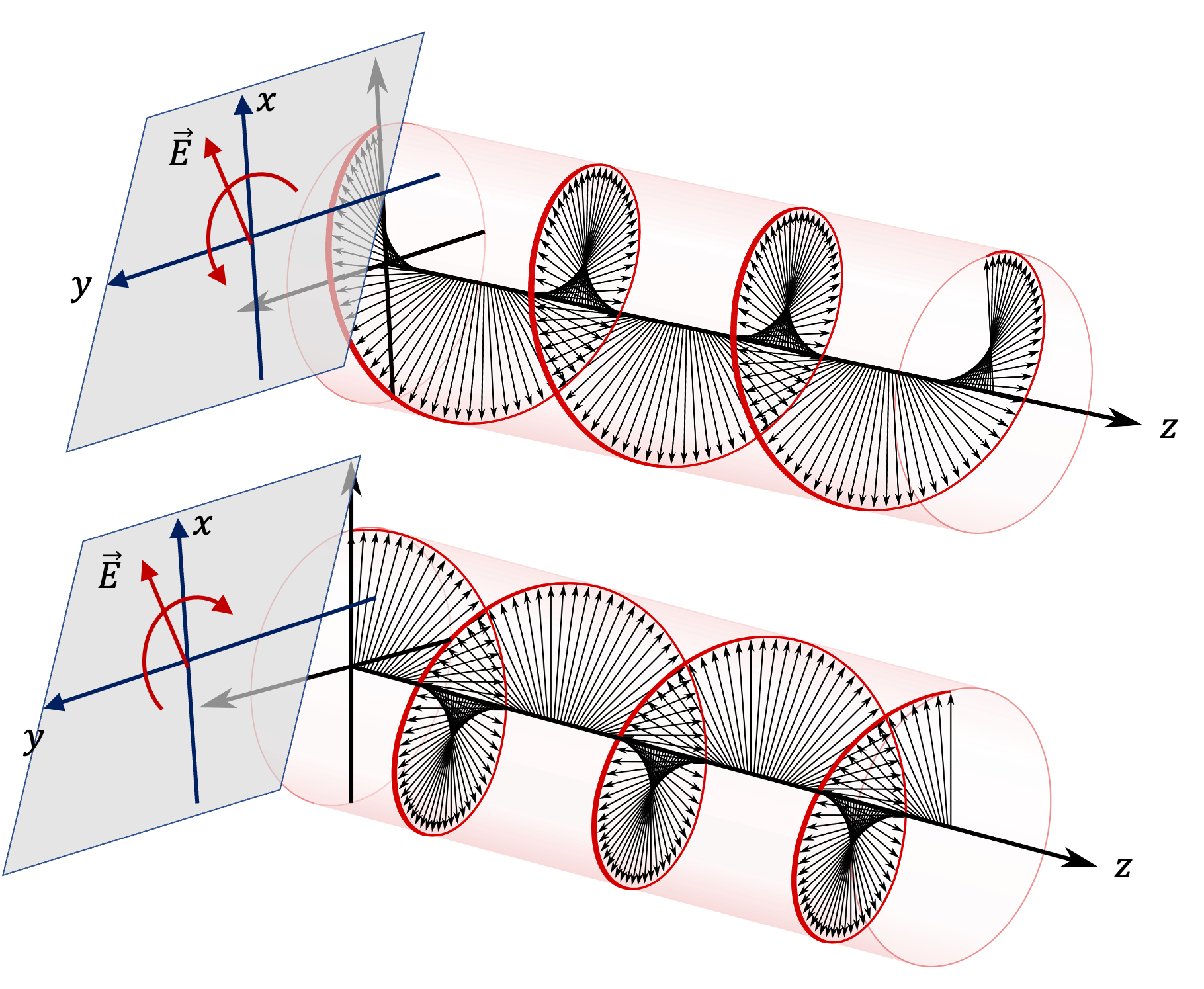
Another polarization of particular interest happens when electric field direction rotates in space and time as shown in Figure 49.5.2. For a wave traveling towards positive \(z\) axis, electric field direction will be in the \(xy\) plane. For linear polarized light, the electric field stays along one line in \(xy\) plane. But, if light is circularly polarized, the direction of polarization rotates in \(xy\) plane as shown in the figure.
A simple polarized wave will have electric field just oscillating back and forth along some fixed line. This light is said to be linearly polarized light. For instance, if an electromagnetic wave is moving in the direction of positive \(z\) axis in vacuum and its electric field at any point is pointed either towards positive or negative \(x\) axis as illustrated in Figure 49.5.1. Then, we say that the wave is linearly polarized in the \(x\) direction. Suppose the wave has wavenumber \(k\) and angular frequency \(\omega\text{.}\) Then, we can represent this wave with amplitude \(E_0\) as
A durable, light weight and compact 7 fresnel with more than excellent light quality, industry standard lighting control options and best in class light ...
There are some naturally occuring crystals, such as tourmaline, that have dichroic property of preferentially absorbing polarization light. Hence, such a crystal will let through light polarized in the perpendicular direction to the direction of polarization that the crystal absorbs. These crystals introduce some other artefacts such as absorption depending on wavelength also and they are not the primary means we obtain polarized light.
(b) Function \(\cos(2\pi t)\) as well as \(\sin(2\pi t)\) has period \(T\) equal to \(1\text{.}\) Therefore, first we compute values of \(\cos(2\pi t)\) and \(\sin(2\pi t)\) at the instants \(t = 0\text{,}\) \(0.2\text{,}\) \(0.4\text{,}\) \(0.6\text{,}\) and \(0.8\text{.}\) Then we draw vector arrows at these instants. We see that this is right-circularly polarized wave if the wave is coming out of page and the vector given is at \(z=0\) or some other constant \(z\) plane.
Using this knowledge, we can immediately write the expressions fro \(E_x\) and \(E_y\) for left-circularly polarized light by just changing the sign of the phase constant in \(E_y\text{.}\)
A linear polarizer lets through the component of the electric field that is parallel to the axis of the polarizer. Consider a linearly polarized EM wave moving towards positive \(z\) axis. Its polarization will be in the \(xy\) plane, say at an angle \(\theta\) from \(x\) axis. This means that the amplitude vector \(\vec E_0\) is in this direction. Suppose it is incident on a linear polarizer whose axis is along \(x\) axis. Then, the wave on the other side will have amplitude equal to the \(x\) component of \(\vec E_0\) and direction of \(x\) axis, which will be
Each application requires a UV solution specific for your operating conditions: radiation spectrum, UV output, light tube temperature, lamp length and geometry. Ideal matching of UV lamps and UV curing systems guarantees the overall best performance of your operations.
A retarder is constructed to retard the phase of one of the components by a set amount. You can buy full-wave, half-wave and quarter-wave plates. The cause relative retardations of the phase by \(2\pi\text{ rad}\text{,}\) \(\pi\text{ rad}\) and \(\pi/2\text{ rad}\) respectively. Also commonly available are compensators which can be used to produce retardation to a arbitrary degree.
If you shine a linearly polarized light on a linear polarizer with direction of polarization of light same as the the polarization direction of the polarizer, then all of the incident light is trnasmitted through the polarizer. On the other hand, if the direction of polarization of incident light perpendicular to the the polarization direction of the polarizer, then all light is blocked.
Figure 49.5.9 shows a setup in which a linear polarizer is rotated between two identical stationary crossed polarizers. Find the intensity of the emerging wave in terms of the intensity \(I_0\) of the light after the first fixed polarizer and the frequency \(f\) of rotation of the rotating polarizer.
Lighting or illumination is the deliberate use of light to achieve practical or aesthetic effects. Lighting includes the use of both artificial light ...
Adding LED spot lights to your landscape allows you to highlight details in your deck, patio, and garden. Shop our energy-efficient ...
There are various types of polarizers depending on the polarization of the light that is emitted from the polarizer. For instance, if light emitted is linearly polarized, we call it a linear polarizer and light emitted is a circularly polarized light we call it a circular polarizer. Linear polarizers are easier to understand and we will mstly look at them.
You can see these expressions by looking at the plane at \(z=0\) and nting that \(\omega=2\pi/T\) where \(T\) is one period. In a quarter cycle, the electric field will go from pointing towards positive \(x\) axis to positive \(y\) axis.
Plot the following time-varying vectors in \(xy\) plane at \(t = 0\text{,}\) \(0.2\text{,}\) \(0.4\text{,}\) \(0.6\text{,}\) and \(0.8\) in units of the period of the cosine or sine functions given. State the direction of rotation of the electric field vectors when observed from the positive \(z\) axis. Here unit vectors in the Cartesian \(x\) and \(y\) are denoted by \(\hat u_x\) and \(\hat u_y\) respectively.
If you look back in Subsection 49.5.2, you will find that to produce right circularly polarized light moving in positive \(z\) axis, we need to introduce delay of \(\pi/2\) in the phase of the \(E_y\) wave relative to the \(E_x\) wave. And similarly for the left-circularly polarized light. Thus, we need polarization dependent wave velocity. Recall that wave velocity in a medium is \(v = c/n\text{.}\) This means we need polarization dependent refractive index. Birefringent materials have just such a property. Therefore, when a linearly polarized light is sent in appropriate direction and through appropriate thickness of a birefringent crystal, the crystal produces the desired delay. These devices are called retarders.
The above describes how you can turn a linearly polarized light into a circularly polarized light. If you want to go the other way around, it is much simpler - you just pass the circularly polarized light through a linear polarizer!
In Section 49.4, we have also seen that if we reflect light at Brewster's angle, then P-wave does not have any reflection but S-wave does have reflection. Therefore, if we reflect an unpolarized light off a surface at the Brewster's angle, then we will get only S-wave in the reflected direction. Now, S-wave is polarized perpendicular to the plane of incidence. This will give light polarized linearly in the direction perpendicular to the incidence plane and parallel to the interface.
Finally, if the direction of polarization of incident light is some angle \(\theta\) to the the polarization direction of the polarizer, then only some of the light is blocked. How much is blocked in this case? To analyze this general case, note that we need to think in terms of electric field to see what is let through and what is blocked.
Buy Levels at India's Best Online Shopping Store. Choose from a huge range of portable laser distance meter, multitester, magnetic & non-magnetic levels.
There are two types of circularly polarized light as shown in Figure 49.5.2. One way to tell the difference is to use handedness. Point the thumb of your right towards the direction of propagation of the wave. Now, if you curl the other fingers and the electric field rotates in time in the same direction as curling of your other fingers of your right hand, then it is said to be right-handed circularly polarized and if it goes in the opposite direction, then you have left-handed circularly polarized. Sometimes clockwise and countecloskwise is also used, but they depend on whether you are looking from the direction of the source or the target.
This is called Malus's law. How can we test this law? We setup an experiment that produces a linearly polarized light with a known direction of polarization, which is then passed through an identical polarizer whose preferred axis makes an angle \(\theta\) with respect to the polarization direction of the polarized light as shown in Figure 49.5.4. In this setup we calle the first polarizer a polarizer and call the second polarizer an analyzer.
Looking at \(E_x\) and \(E_y\text{,}\) you would notice that if the arguments of the cosines, i.e., the phases, of \(E_x\) and \(E_y\) were same, you would not get any rotation. The rotation of electric field, which is a vector sum of the \(x\) and \(y\) parts, comes from the lag of phase of the \(E_y\) wave, the full value of \(E_y\) occurs \(T/4\) later than it occurs for \(E_x\text{.}\)
where \(\hat u_x\) is a unit vector in the direction of positive \(x\) axis, usually denoted by \(\hat i\) also. The line of polarization for a linearly polarized light remains fixed in time although the direction of electric field varies since it oscillates back anf forth along the line.
Often we describe a circularly polarized light by stating its component electric fields. For instance, for right-circularly polarized light moving in the direction of \(z\) axis of Figure 49.5.2, we can give \(E_x\) and \(E_y\) wave functions.
Camera & Camcorder Lights · 10,571 Results · Sort · Type · Brand · Power Source · LED/Bulb Count · Compatible Brand · Condition.
We use Malus's law for one polarizer at a time and get the intensities. We need to work oiut angles between successive polarizers at instant \(t\text{.}\) Let us choose time \(t=0\) to be the instant when the rotating polarizer is aligned with the first fixed polarizer. Then, angle in which the rotating polarizer will be pointed with respect to the first polarizer will be
The wave is passed through a linear polarizer whose polarizing axis is pointed \(45^\circ\) counterclockwise to the \(x\) axis. Find the intensity of the emergent wave in terms of the intensity of the incident wave.
LED Lighting adds energy efficient, long-lasting light to every space in your home—from desktop lamps to inside your microwave.
Use Malus's law for each polarizer. Note tha angle between the rotating polarizer and either of the two polarizers will be same.
In general, the direction of electric field in the electromagnetic wave is called the polarization direction of light. A light source may be producing very large number of waves, each of which has electric field in a random direction. This light will not be polarized. We call such light \(unpolarized\text{.}\)
A beam of light consisting of two wavelengths, 650nm and 520nm, is used to obtain interference fringes in a Young's double-slit experiment.
Natural light such as the light from the Sun is unpolarized. It is generally a random mixture of various waves of different polarizations and frequencies. There are devices that act as filter of light and let through light with a particular type of polarization. These devices are called polarizers.
More Info on Advanced illumination ... Manufactures LED lighting for machine vision. The company offers a broad range of standard and customizable light solutions ...
In Section 49.4 we saw important role of the direction of the electric field in determining how much of an electromagnetic wave will be reflected or transmitted when light is incident. A S-polarized wave (also known as transverse electric or TE) behaves differently than a P-polarized wave (also know as transverse magnetic or TM). That was one example of role of direction of electric field.
Color Modification: Color modification occurs when a colored surface is struck by a different colored light. Depending on the color of the surface, it will ...
We use Malus's law for one polarizer at a time and get the intensities. The angles between the electric field direction of the incident wave and the polarizer in these cases are \(30^\circ\text{,}\) \(60^\circ\text{,}\) and \(30^\circ\text{,}\) respectively.
(a) Function \(\cos(2\pi t)\) has period \(T\) equal to \(1\text{.}\) Therefore, first we compute values of \(\cos(2\pi t)\) at the instants \(t = 0\text{,}\) \(0.2\text{,}\) \(0.4\text{,}\) \(0.6\text{,}\) and \(0.8\text{.}\) Then we draw arrows along \(x\) axis since the direction is always aling \(x\) axis. For negative values, the arrow is pointed towards negative axis.


 Ms.Cici
 8618319014500