
Continuous Lighting & LED Camera Lights - led lights for camera
Light is a transverse wave, i.e. its electromagnetic and magnetic fields are disturbed at right angles relative to the direction of travel of the light waves. Or, it can be said that light waves oscillate perpendicular to their direction of travel.
The Ring Floodlight Cam Wired Pro delivers excellent HD video, accurately detects motion, and is bright enough to light up most yards.
Take any object and shoot under cross-polarised light and you’ll see that it is probably darker than you expected it to be, and you might even spot a slight shift in hue and saturation. So, as you explore materials in the real-world, do observe and think about how the colour might not quite be what you think it is.
Circularly polarizedlight

For another example, as the sun moves across the sky the angle of the sun’s light striking a window will change. At some point the light will reflect off the window, or be polarized, at an angle perceived as glare.
When the light wave hits a surface, the reflected component will still maintain its polarisation. However, the diffuse component will be unpolarised. This is a good thing as it will allow us to have reference of the specular side of things, but by polarising just the lights, we are not getting reference of the diffuse only. To do this, we’ll need to look at cross-polarisation.
Polarization oflight
The sky is blue because sunlight strikes the molecular structure of the atmosphere and scatters, which polarizes the light in a specific direction. As the angle of the sun relative to the atmosphere changes the polarization angle of the light also changes, and the human eye perceives color changes from dawn to midday to dusk.
P-polarizedlight
Similarly, in machine vision, artificial polarization techniques help developers select or restrict the direction of the light waves that enter a camera lens and strike an image sensor. The three basic ways to artificially polarize light are linear polarization, circular polarization, and elliptical polarization, with the latter two methods serving as extensions of linear polarization and not widely used in machine vision.
We should already know at this stage that a light wave is an electromagnetic wave. For a deeper breakdown of light, make sure to check out this page:
In this document, we’ll dive into how we can control light in order to support us in the capture of texture and look development reference. And just a quick note, I am not a scientist (although a big, big fan of science), therefore, if I use the wrong terminology, feel free to let me know and I can make the corrections as required 😉
The dynamic process allows for the correction of glare that may originate from different angles on individual items to be inspected, making it easier to extract features, scratches, or even to see material stress in plastic.
AutoMeter's Electronic Programmable Speedometer provides an easy-to-install and easy-to-calibrate solution that will help keep your speed exactly where it ...
Polarization - Definition of Concepts, Techniques, and TechnologiesPolarization, a filtering technique used for decades by photographers for image enhancement, also sees widespread use in commercial applications, including machine vision image acquisition. With polarizing cameras and imaging components increasingly entering the vision application mainstream since 2018, new applications and uses for polarization in machine vision continue to emerge. Understanding the growing list of polarization applications requires a discussion of the latest polarization cameras and sensors and an understanding of the benefits and limitations associated with the use of polarization technology.Polarization concepts Light is a transverse wave, i.e. its electromagnetic and magnetic fields are disturbed at right angles relative to the direction of travel of the light waves. Or, it can be said that light waves oscillate perpendicular to their direction of travel. Natural light, and virtually all artificial light (LEDs, incandescent lights, fluorescent lights, etc.) is unpolarized or weakly polarized. Natural light travels in any radial direction from the source of the light (Figure 1). Imagine a beam of light. Light waves oscillate 360° from every point along that beam. (An oversimplification, to illustrate the concept.) Polarized light, on the other hand, is light in which the waves travel in only one, specific direction. Light can be polarized in nature by absorption, refraction, reflection, scattering, and birefringence (double refraction). For example, when light strikes water, it can be reflected linearly perpendicular, i.e. polarized in that specific direction, to the surface of water, which we experience as glare. For another example, as the sun moves across the sky the angle of the sun’s light striking a window will change. At some point the light will reflect off the window, or be polarized, at an angle perceived as glare. The sky is blue because sunlight strikes the molecular structure of the atmosphere and scatters, which polarizes the light in a specific direction. As the angle of the sun relative to the atmosphere changes the polarization angle of the light also changes, and the human eye perceives color changes from dawn to midday to dusk.
Before we dive in, I just want to give a huge shout out to our collaborative partner, Clear Angle Studios, for supporting CAVE Academy and allowing us to capture high-quality datasets, and share the results on our Wiki.
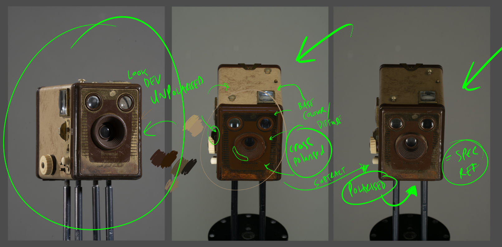
And here is an example of a prop shot under cross polarised and polarised light, and then the subtraction (and desaturation) process.
Software can then dynamically handle the selection of either individual wave angles, or the computational manipulation of the variety of wave angles, to analyze the image in ways that only were possible previously by providing sets of filters, multiple images, or even multiple sensors, to acquire multiple polarized analyses of the individual image, itself.
If you're looking for some UVA lights, you may come across two specifications - 365nm or 395nm. What does that mean, and which one is best?
To capture cross-polarised shots, we’ll need to cover all the light sources with linear polarising filters. If you are using multiple lights, the polarising filter must be going in the same direction (for example, vertical). You DO NOT want one light to have a filter running horizontally and another light to have a filter running vertically. If you then apply a circular polarising filter (CPF) onto your camera lens, and then rotate the CPF to be perpendicular (in this example, horizontal) to the light filters, you should then be able to remove all the highlights and the glare, and be left with wondrous colour. Easy peasy.
New technologies and components A polarizing image sensor makes a polarization filter part of the image sensor, versus a separate component placed over the sensor. The Photron Crysta by Photron (San Diego, CA, USA; www.photron.com) and PolarCam from 4D Technology (Tucson, AZ, USA; www.4dtechnology.com), to cite two examples, have been in the marketplace for some time and make use of on-sensor polarization. The IMX250MZR/MYR (monochrome/color) Polarsens sensor from Sony (Tokyo, Japan; www.sony.com) represents a recent implementation of on-sensor polarization technology. The polarization elements are fabricated right into the silicon, under the microlens (Figure 4), which makes the sensor unique. In the color sensor, color filters are located directly underneath the polarizers. The polarizers in Sony’s sensor, a microscopic implementation of a wire-grid polarizer over every lens on the sensor, have 0°, 45°, 90°, and 135° polarization angles in four-pixel groups. The groups are interpolated, reducing the sensor’s overall functional resolution by 4x. In other words, each four-pixel block equates to one pixel of output.By interpolating the images from each four-pixel block, the sensor gathers considerable information about the linear polarization occurring on the surface of the object being viewed. These interpolated pixels allow a very accurate definition of the exact direction and intensity of the polarization within each four-pixel group.
The polarizers in Sony’s sensor, a microscopic implementation of a wire-grid polarizer over every lens on the sensor, have 0°, 45°, 90°, and 135° polarization angles in four-pixel groups. The groups are interpolated, reducing the sensor’s overall functional resolution by 4x. In other words, each four-pixel block equates to one pixel of output.
FS offers a range of fiber optic light sources, choose from a variety of cost-effective light sources. Money Back Guarantee.
Elliptical polarization
Each line in a time delay integration (TDI) setup is successively struck with each of the four polarization angles (Figure 6). The four images then combine into a composite image, providing a full-resolution polarization image, versus the four-pixel interpolated image created by an area sensor like the IMX250MZR/MYR.
Dichroic, thin-film, and wire-grid polarizers represent the most common components used in machine vision to linearly polarize light. Wire-grid polarizers specifically can withstand the power levels of lasers, which can be useful in factory and scientific environments.
The small colored dots in the background of each plot show the color distributions of each lighting environment. ... ... Yet the influence of lighting ...
Shooting under cross-polarised light is extremely useful for texture artist and a fantastic way to gain a truer reference of the surface colour and the type of material itself. For metallic materials for example, we’ll just be left with black as true metals do not have any diffuse colour. So not only is it a great way to find the diffuse colour of non-metals but also a great way of figuring out what is a metallic object and what is non-metal.
With more than 35 years of experience, David Dechow is the founder and owner of Machine Vision Source (Salisbury, NC, USA), a machine vision integration firm. He has been the founder and owner of two successful machine vision integration companies. He is the 2007 recipient of the AIA Automated Imaging Achievement Award honoring industry leaders for outstanding career contributions in industrial and/or scientific imaging.
Photon polarization
Even if the light projected onto an object is polarized in order to limit the potential number of reflective polarization angles, the reflective properties of the object may still create unwanted polarization when the light reflects off the object. Employing two filters allows for finer control of the light angles that enter the camera, ensuring the desired crispness of the image.
LED Lighting · LED Lighting Upgrade NSW · LED Lighting Upgrade for Building ... SMA Inverters. SMA Inverters are No.1 European Solar PV inverter ...
Polarized light, on the other hand, is light in which the waves travel in only one, specific direction. Light can be polarized in nature by absorption, refraction, reflection, scattering, and birefringence (double refraction). For example, when light strikes water, it can be reflected linearly perpendicular, i.e. polarized in that specific direction, to the surface of water, which we experience as glare.
Common polarization techniques in machine vision include inspection of glass and highly reflective materials. Raw and machined metal have grain at a microscopic level that can lead to linear polarization, making the use of a polarization filter useful. Plastic and glass, automotive, packaged materials, semiconductor, and LCD inspection applications commonly make use of polarization filters.
For look development, shooting reference with unpolarised light is a good idea as on most occasions, that’s how we’ll be seeing the assets in real-life. Therefore, when shooting look development reference, you should shoot with no polarising filters are on the lights and no cross polarising filter is on the lens. Don’t forget to shoot the Macbeth chart reference, so you have a ground truth of how colour is captured with your selected camera, and from which you’ll be able to grade and expose your images later on.
There are many ways in which unpolarised light can be polarised. For example, through reflection, refraction and scattering but for now, we’ll stick to using a filter.
So that means the lights and the camera should not move between the images. Because of my shoot setup, removing the polarising filters from the lights usually results in some movement to the lights themselves, so the last thing I’ll shoot is the actual look dev (unpolarised) reference. I don’t mind if the look dev images are not perfectly aligned to the cross-polarised/polarised images. If you can, ideally you would have a separate set of lights that are polarised and unpolarised, and you would fire off the specific lights for the specific shot.
DOLP, or degree of linear polarization (the intensity and direction of linear polarization as it’s interpreted from the four angles of each four-pixel group), and AOLP, or angle of linear polarization, (the angle of the light as it reaches the sensor plane) can be adjusted. Adjusting these parameters allows fine control of polarization similar to how a photographer rotates their polarization filter to achieve the desired crispness of image (Figure 5).
No technology provides a global cure for imaging challenges, however. Polarization is another tool in the toolbox of a vision system designer or integrator.
Unpolarizedlight
When done correctly, cross-polarised light can strip out all the reflection and the result can then be graded, projected, cleaned up, and then plugged into the ‘base_colour’ or ‘diffuse’ component of your shader, resulting in a more physically accurate result.
So hopefully at this stage you can see the benefits from shooting assets under UNPOLARISED (look dev), POLARISED (spec ref) and CROSS POLARISED (diffuse ref) light. If you have any thoughts or other ideas, it would be great to hear from you.
A polarizing image sensor makes a polarization filter part of the image sensor, versus a separate component placed over the sensor. The Photron Crysta by Photron (San Diego, CA, USA; www.photron.com) and PolarCam from 4D Technology (Tucson, AZ, USA; www.4dtechnology.com), to cite two examples, have been in the marketplace for some time and make use of on-sensor polarization.

Returning to the example of the sun reflecting off the surface of water and producing glare, a photographer may employ a polarization filter to remove that glare, improving the image by filtering light at the specific angle causing the glare.
Edmund Optics has been a leading producer of optics, imaging, and laser optics for 80 years. Discover the latest optical and imaging technology.
Circular polarising filters (CPF) are made of special materials that are able to block one of the two planes of vibrations depending on how you rotate the filter. Do note, however, that by using a CPF, you will be reducing the amount of light transmission, and therefore, you will need to shoot a Macbeth chart with and without the CPF. This will allow you to properly grade your cross-polarised images later on for texture projection.
Here is an example shot at Clear Angle Studios using cross polarised light, (left) polarised light (middle), and what happens when we subtract one from the other, which reveals the spec (of which I have desaturated).
This will not be an in-depth walkthrough of setting up a look dev and texture shoot, but below, you’ll be able to watch a short timelapse video of how I go about setting up a shoot (although this is generally configured depending on the type of asset I am shooting).
Polarization techniques Returning to the example of the sun reflecting off the surface of water and producing glare, a photographer may employ a polarization filter to remove that glare, improving the image by filtering light at the specific angle causing the glare. Similarly, in machine vision, artificial polarization techniques help developers select or restrict the direction of the light waves that enter a camera lens and strike an image sensor. The three basic ways to artificially polarize light are linear polarization, circular polarization, and elliptical polarization, with the latter two methods serving as extensions of linear polarization and not widely used in machine vision. Dichroic, thin-film, and wire-grid polarizers represent the most common components used in machine vision to linearly polarize light. Wire-grid polarizers specifically can withstand the power levels of lasers, which can be useful in factory and scientific environments. Polarization filters function by selecting or restricting light waves traveling in a single plane. The orientation of the filter determines the orientation of the light waves that can pass through the filter, thereby selecting one set of light waves to advance and preventing others from continuing (Figure 2). Use of multiple filters, each of which prevent the passage of light waves at different orientations, allows finer attenuation of light. A filter only allowing vertical light to pass, followed by a filter only allowing horizontal light to pass, would act together to block most of the light waves passing through the filter pair.
Polarization, a filtering technique used for decades by photographers for image enhancement, also sees widespread use in commercial applications, including machine vision image acquisition. With polarizing cameras and imaging components increasingly entering the vision application mainstream since 2018, new applications and uses for polarization in machine vision continue to emerge.
Placing a polarizer only over the camera lens, and thus only polarizing the light reflecting off the object to be inspected, may sometimes be an effective technique but far more often not. To demonstrate the point, consider the example of photography.
Understanding the growing list of polarization applications requires a discussion of the latest polarization cameras and sensors and an understanding of the benefits and limitations associated with the use of polarization technology.
Dechow is a regular speaker at conferences and seminars worldwide, and has had numerous articles on machine vision technology and integration published in trade journals and magazines. He has been a key educator in the industry and has participated in the training of hundreds of machine vision engineers as an instructor with the AIA Certified Vision Professional program.
Lightpath Health is a nonprofit organization dedicated to developing and investing in programs that expand access to primary care.
Applications and implementation Common polarization techniques in machine vision include inspection of glass and highly reflective materials. Raw and machined metal have grain at a microscopic level that can lead to linear polarization, making the use of a polarization filter useful. Plastic and glass, automotive, packaged materials, semiconductor, and LCD inspection applications commonly make use of polarization filters. The proper way to employ polarization in an inspection environment typically involves polarizing both the light source and the reflected light (Figure 3) with a polarizer placed at the source of the light, at an angle that benefits the application, and a second polarizer placed at the same or a complementary angle, onto the lens of the camera conducting the inspection. Even if the light projected onto an object is polarized in order to limit the potential number of reflective polarization angles, the reflective properties of the object may still create unwanted polarization when the light reflects off the object. Employing two filters allows for finer control of the light angles that enter the camera, ensuring the desired crispness of the image. Placing a polarizer only over the camera lens, and thus only polarizing the light reflecting off the object to be inspected, may sometimes be an effective technique but far more often not. To demonstrate the point, consider the example of photography. The polarizers used by photographers rotate, to allow the photographer to attune the polarizer to the precise angle at which the light is being polarized by the surface of the subject in the scene. The photographer tunes the angle of polarization as needed for different scenes, not a practical technique for automated imaging in machine vision. Take, for example, parts on a conveyor belt rapidly passing underneath a camera for inspection. It’s impossible to achieve perfect, replicable results during parts inspection, even with polarized light and filter working in concert, because there will likely be variances in the position of objects relative to the camera, which affects the angles at which polarized light reflects off the surface of the object. However, a new technology and new components becoming readily available overcome the limitation.
Take, for example, parts on a conveyor belt rapidly passing underneath a camera for inspection. It’s impossible to achieve perfect, replicable results during parts inspection, even with polarized light and filter working in concert, because there will likely be variances in the position of objects relative to the camera, which affects the angles at which polarized light reflects off the surface of the object. However, a new technology and new components becoming readily available overcome the limitation.
Linear polarization
Unpolarised light is a light wave that vibrates in a variety of directions. For simplification, let’s say it vibrates in a vertical and horizontal plane. Examples of unpolarised light include light emitted from the sun, a candle, a lightbulb or an LED panel.
Use of multiple filters, each of which prevent the passage of light waves at different orientations, allows finer attenuation of light. A filter only allowing vertical light to pass, followed by a filter only allowing horizontal light to pass, would act together to block most of the light waves passing through the filter pair.
Do note, however, that some sources will emit polarised light, for example, the light from your computer screen will more than likely emit polarised light.
PRODUCT FEATURES · The FPM-55 Fiber Optic Power Meter for measuring wavelengths from 800-1650 nm, with a mere 0.01 dB resolution · The FLS-55 Fiber Optic Light ...
The cross-polarised and polarised images will need to line up perfectly in order to subtract the specular component (which can then be used as visual reference to compare against the specular AOV).
Do note, however, that by using filters on the lights and the lens, you’ll be reducing the amount of light transmission. Therefore, you’ll want to double-check your exposure as you shoot and make sure to shoot the Macbeth chart for each of the setups (unpolarised, polarised and cross-polarised). This will allow you to grade and expose your images later on.
The IMX250MZR/MYR (monochrome/color) Polarsens sensor from Sony (Tokyo, Japan; www.sony.com) represents a recent implementation of on-sensor polarization technology. The polarization elements are fabricated right into the silicon, under the microlens (Figure 4), which makes the sensor unique. In the color sensor, color filters are located directly underneath the polarizers.
Natural light, and virtually all artificial light (LEDs, incandescent lights, fluorescent lights, etc.) is unpolarized or weakly polarized. Natural light travels in any radial direction from the source of the light (Figure 1). Imagine a beam of light. Light waves oscillate 360° from every point along that beam. (An oversimplification, to illustrate the concept.)
Polarization filters function by selecting or restricting light waves traveling in a single plane. The orientation of the filter determines the orientation of the light waves that can pass through the filter, thereby selecting one set of light waves to advance and preventing others from continuing (Figure 2).
By interpolating the images from each four-pixel block, the sensor gathers considerable information about the linear polarization occurring on the surface of the object being viewed. These interpolated pixels allow a very accurate definition of the exact direction and intensity of the polarization within each four-pixel group.
Cross polarisation is the process of polarising the incident light and the reflected light using two polarisers with perpendicular orientation. By doing this, we can effectively remove the specular reflectance and be left with just the diffuse component.
A new fluorescence microscopy technique has come to the fore that is faster and less phototoxic than other microscopy techniques.
The proper way to employ polarization in an inspection environment typically involves polarizing both the light source and the reflected light (Figure 3) with a polarizer placed at the source of the light, at an angle that benefits the application, and a second polarizer placed at the same or a complementary angle, onto the lens of the camera conducting the inspection.
Here at CAVE Academy the beauty of giving and sharing is very close to our hearts. With that spirit, we gladly provide Masterclasses, Dailies, the Wiki, and many high-quality assets free of charge. To enable the team to create and release more free content, you can support us here: Support CAVE Academy
We can transform unpolarised light into polarised light by using a polarising filter that sits in front of the emitting light, or by fitting a circular polarising filter on the lens. The chemical composition of the filter can restrict the vibrations of the electromagnetic wave to a single plane (either vertical or horizontal). By restricting one half of the vibrations, we’ll also be reducing one-half of the intensity of the light, so we’ll need to factor this in when shooting reference. Again, this is where the Macbeth chart comes in, so make sure to shoot it under polarised light.
On-chip polarization sensors, now available to virtually any camera manufacturer, drive advances in software and solutions that developers and manufacturers provide for machine vision systems. An increasing number of viable polarization applications can now be expected.
Polarization techniques can also be deployed in line scan cameras like the quad-linear Piranha4 from Teledyne DALSA (Waterloo, ON, Canada; www.teledynedalsa.com), which has four linear sensor lines, each of which has an on-sensor polarizer, with each sensor line set to a different polarization angle.
The polarizers used by photographers rotate, to allow the photographer to attune the polarizer to the precise angle at which the light is being polarized by the surface of the subject in the scene. The photographer tunes the angle of polarization as needed for different scenes, not a practical technique for automated imaging in machine vision.


 Ms.Cici
 8618319014500