
Causes/Inheritance - Spinal Muscular Atrophy (SMA) - sma led lights
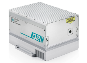
A CW or continuous-wave laser is any laser with a continuous flow of pump energy. It emits a constant stream of radiation, as opposed to a q-switched or mode-locked pulsed laser with a pulsed output beam. A laser is typically defined as having a pulse width greater than 250 ms. The first CW laser was a helium-neon (HeNe) gas laser, developed in 1960, which you can read more about in this blog “HeNe Lasers: Bright Past, Brighter Future.” If you want to read more about the types of CW Lasers we offer, check out the Overview of CW Lasers section on our Lasers 101 Page!
Infrared LaserPointer for Rifle
There are many different types of laser designation systems used by the military today. Still, they all share the same basic functionality and outcome. At a glance, the laser requirements seem relatively straightforward. The laser needs to be invisible to the human eye, and it needs to have a programmable pulse rate. Still, when you look in more detail, many small factors add up to big problems if not appropriately addressed. Excellent divergence and beam pointing stability, low timing jitter, and rugged, low SWaP design are all critical features of a good laser designation source. Read more on these critical features in this article: “What are the Critical Laser Source Requirements for Laser Designation?” Get more information from our Lasers 101, Blogs, Whitepapers, FAQs, and Press Release pages in our Knowledge Center!
Reflection occurs when light traveling through one material bounces off a different material. The reflected light continues to travel in a straight line, but in a different direction.
On the surface, this seems like a simple question since Raman is a nonlinear optical effect and therefore the tighter the beam can be focused the higher the conversion efficiency. Seemingly a single-mode laser would be preferable, but in practice there are other factors that can complicate the situation. The first question you should ask yourself when considering which type of laser to choose is whether you are doing microscopy or bulk sampling. If the answer to that question is microscopy, then you immediately should go with a single mode laser. Since the goal of any microscopy system is to produce the highest resolution image possible, the number one consideration should be how tightly can the laser beam be focused down. However, there are several other considerations when choosing between multimode and single-mode. Learn which is best for you in this article: “Multimode vs Single-Mode Lasers for Raman Spectroscopy.” Get more information from our Lasers 101, Blogs, Whitepapers, FAQs, and Press Release pages in our Knowledge Center!
Shown is a colour diagram of light reflecting off a rough surface. Along the bottom of the diagram is a long grey shape, with a flat bottom edge and a jagged, uneven top edge. This is labelled, "Surface." Three diagonal, parallel blue arrows point down to the surface. Where each arrow touches the surface, a red arrow points up. These are at three completely different angles.
What’s the difference between single transverse mode & single longitudinal mode? Within the laser community, one of the most overused and often miscommunicated terms is the phrase “single mode.” This is because a laser beam when traveling through air takes up a three-dimensional volume in space similar to that of a cylinder; and just as with a cylinder, a laser beam can be divided into independent coordinates each with their own mode structure. For a cylinder we would call these the length and the cross-section, but as shown in the figure below for a laser beam, we define these as the transverse electromagnetic (TEM) plane and the longitudinal axis. Both sets of modes are fundamental to the laser beam’s properties, since the TEM modes determine the spatial distribution of the laser beams intensity, and the longitudinal modes determine the spectral properties of the laser. As a result, when a laser is described as being “single-mode” first you need to make sure that you truly understand which mode is being referred to. Meaning that you must know if the laser is single transverse mode, single longitudinal mode, or both. Get all the information you need in this article: “What is Single Longitudinal Mode?” Get more information from our Lasers 101, Blogs, Whitepapers, FAQs, and Press Release pages in our Knowledge Center!
Near Infrared (NIR) laser sources are perhaps the single most diverse category of solid-state lasers; with IR laser diodes, diode-pumped solid-state (DPSS) lasers, flashlamp-pumped solid-state lasers, and fiber lasers all emitting in the IR laser spectrum. IR laser diodes are capable of extremely high-power outputs, up to several kilowatts in the case of diode laser stacks, making them ideal for machining applications such as cladding and welding. Near-infrared pulsed lasers are also available with an extensive range of pulse widths and peak powers. IR fiber lasers can not only produce high output powers, but they are also able to provide extremely narrow linewidth (and therefore long coherence lengths) making them ideal for a wide variety of LIDAR applications.
Within the laser community, one of the most overused and often miscommunicated terms is the phrase “single mode.” This is because a laser beam when traveling through air takes up a three-dimensional volume in space similar to that of a cylinder; and just as with a cylinder, a laser beam can be divided into independent coordinates each with their own mode structure. For a cylinder we would call these the length and the cross-section, but as shown in the figure below for a laser beam, we define these as the transverse electromagnetic (TEM) plane and the longitudinal axis. Both sets of modes are fundamental to the laser beam’s properties, since the TEM modes determine the spatial distribution of the laser beams intensity, and the longitudinal modes determine the spectral properties of the laser. As a result, when a laser is described as being “single-mode” first you need to make sure that you truly understand which mode is being referred to. Meaning that you must know if the laser is single transverse mode, single longitudinal mode, or both. Get all the information you need in this article: “What is Single Longitudinal Mode?” Get more information from our Lasers 101, Blogs, Whitepapers, FAQs, and Press Release pages in our Knowledge Center!
If light is travelling in one material and then refracts in a second material, it will bend towards the normal if the index of refraction of the second material, n2, is greater than the index of refraction of the first material, n1.
RPMC’s extensive selection of NIR lasers offers unparalleled versatility, covering everything from compact laser diodes to high-power fiber and DPSS lasers with powers up to 3 kW. These lasers, available in free-space or fiber-coupled configurations, deliver both CW and pulsed outputs, making them adaptable to a broad range of applications from industrial processing to advanced scientific research. Our NIR options support precision tasks requiring high beam quality, pulse flexibility, and customizable wavelength control, ideal for LIDAR, spectroscopy, and materials processing. With wavelengths spanning ≈750 to 1400 nm, we also provide options in the eye-safe 1.5 µm region, essential for applications prioritizing safety. With component to turnkey solutions, RPMC’s NIR lasers combine precision, power, and flexibility to meet the most demanding application requirements.
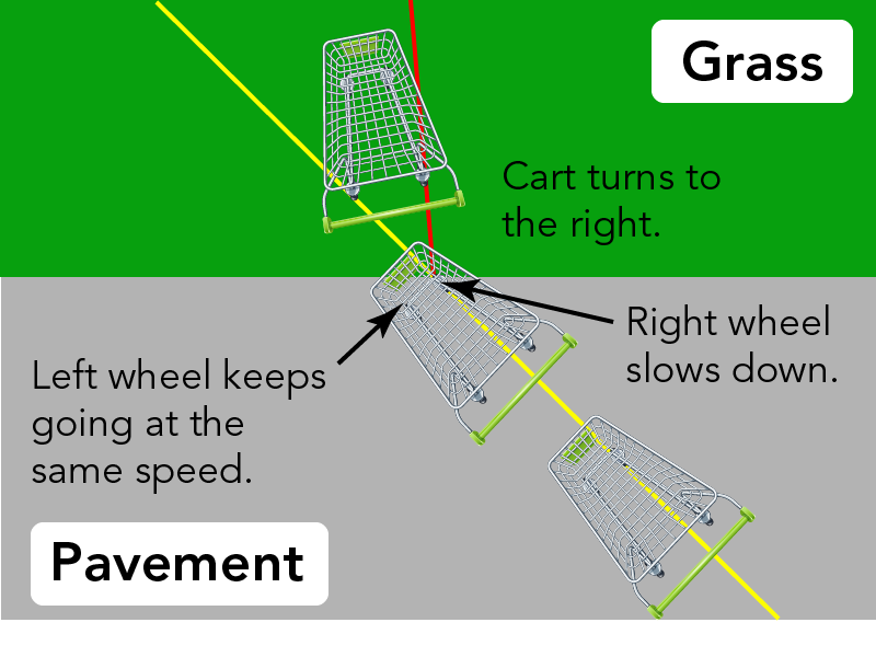
Item contShown is a colour diagram of a shopping cart moving from pavement onto grass. The bottom two thirds of the image is grey. This is labelled "Pavement." The top is green and labelled "Grass." A straight yellow line stretches across the illustration, from near the lower right corner, to near the upper right corner. Two shopping carts are shown from above, along the yellow line. This illustrates that one cart is moving in a straight line, across the grey pavement, toward the grass. The front right corner of the second cart is on the green background, while the rest is on the grey. The front right wheel is labelled "Right wheel slows down." The front left wheel of the cart is labelled "Left wheel keeps going at the same speed." A third cart is completely on the green background. It does not follow the yellow line of the other two.There is a red line under this cart, leading from the edge of the pavement, to a point near the top centre of the illustration. This cart is labelled "Cart turns to the right."ent
What is white light? This hands-on activity, by Let’s Talk Science, shows how it is possible to combine colours to make white light.
Infrared Laserdiode
When light passes through a lens that is concave on both sides (biconcave lens), the light is refracted outwards. These beams of light are said to be diverging. With this type of lens, the focal point is in front of the lens.
A laser source used for LIBS must have a sufficiently large energy density to ablate the sample in as short a time possible. Typically, pulsed DPSS lasers take center stage here. However, it’s been shown that pulsed fiber lasers can also be a great option. For example, you could utilize fiber lasers to measure detection limits as low as micrograms per gram (µg/g) for many common metals and alloys, including aluminum, lithium, magnesium, and beryllium. Analytical performances showed to be, in some cases, close to those obtainable with a traditional high-energy Nd:YAG laser. The beam quality of fiber lasers, in conjunction with longer pulse widths, resulted in significantly deeper and cleaner ablation craters. If you want to learn more about LIBS and ideal laser sources, check out either this blog: “OEM Fiber Lasers for Industrial Laser Induced Breakdown Spectroscopy,” or this blog: “Laser Induced Breakdown Spectroscopy (LIBS) in Biomedical Applications.” Get more information from our Lasers 101, Blogs, Whitepapers, FAQs, and Press Release pages in our Knowledge Center!
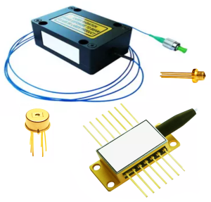
A Laser Diode or semiconductor laser is the simplest form of Solid-State Laser. Laser diodes are commonly referred to as edge emitting laser diodes because the laser light is emitted from the edge of the substrate. The light emitting region of the laser diode is commonly called the emitter. The emitter size and the number of emitters determine output power and beam quality of a laser diode. Electrically speaking, a laser diode is a PIN diode. The intrinsic (I) region is the active region of the laser diode. The N and P regions provide the active region with the carriers (electrons and holes). Initially, research on laser diodes was carried out using P-N diodes. However, all modern laser diodes utilize the double-hetero-structure implementation. This design confines the carriers and photons, allowing a maximization of recombination and light generation. If you want to start reading more about laser diodes, try this whitepaper “How to Improve Laser Diode Lifetime.” If you want to read more about the Laser Diode Types we offer, check out the Overview of Laser Diodes section on our Lasers 101 Page!
There are a great many factors that can increase or decrease the lifetime of a laser diode. One of the main considerations is thermal management. Mounting or heatsinking of the package is of tremendous importance because operating temperature strongly influences lifetime and performance. Other factors to consider include electrostatic discharge (ESD), voltage and current spikes, back reflections, flammable materials, noxious substances, outgassing materials (even thermal compounds), electrical connections, soldering method and fumes, and environmental considerations including ambient temperature, and contamination from humidity and dust. Read more about these critical considerations and contributing factors in this article: “How to Improve Laser Diode Lifetime: Advice and Precautions on Mounting.” Get more information from our Lasers 101, Blogs, Whitepapers, FAQs, and Press Release pages in our Knowledge Center!
Infrared laservs redlaser
Along a rough surface, the normal points in different ways. This means that all of the light is reflected in different directions.
With 1000s of fielded units, and over 25 years of experience, providing OEMs, contract manufacturers, and researchers with the best laser solution for their application, our expert team is ready to help! Working with RPMC ensures you are getting trusted advice from our knowledgeable and technical staff on a wide range of laser products. RPMC and our manufacturers are willing and able to provide custom solutions for your unique application.
A pulsed laser is any laser that does not emit a continuous-wave (CW) laser beam. Instead, they emit light pulses at some duration with some period of ‘off’ time between pulses and a frequency measured in cycles per second (Hz). There are several different methods for pulse generation, including passive and active q-switching and mode-locking. Pulsed lasers store energy and release it in these pulses or energy packets. This pulsing can be very beneficial, for example, when machining certain materials or features. The pulse can rapidly deliver the stored energy, with downtime in between, preventing too much heat from building up in the material. If you would like to read more about q-switches and the pros and cons of passive vs active q-switches, check out this blog “The Advantages and Disadvantages of Passive vs Active Q-Switching,” or check out our Overview of Pulsed Lasers section on our Lasers 101 Page!
Delivered twice each month, we're connecting the most important educational and global topics of our time across all classrooms through STEM-based resources, programs, and activities.
IRLaserPointer military
Laser Diodes and VCSELs are semiconductor lasers, the simplest form of Solid State Lasers. Laser diodes are commonly referred to as edge emitting laser diodes because the laser light is emitted from the edge of the substrate. The light emitting region of the laser diode is commonly called the emitter. The emitter size and the quantity of emitters determine output power and beam quality of a laser diode. These Fabry Perot Diode Lasers with a single emission region (Emitter) are typically called laser diode chips, while a linear array of emitters is called laser diode bars. Laser diode bars typically use multimode emitters, the number of emitters per substrate can vary from 5 emitters to 100 emitters. VCSELs (Vertical Cavity Surface Emitting Laser) emit light perpendicular to the mounting surface as opposed to parallel like edge emitting laser diodes. VCSELs offer a uniform spatial illumination in a circular illumination pattern with low speckle. If you want to read more about lasers in general, and help narrowing down the selection to find the right laser for you, check out our Knowledge Center for our Blogs, Whitepapers, and FAQ pages, as well as our Lasers 101 Page!
The output wavelength of a semiconductor laser is based on the difference in energy between the valance and conduction bands of the material (bandgap energy). Since the energy of a photon is inversely proportional to its wavelength, this means that a larger bandgap energy will result in a shorter emission wavelength. Due to the relatively wide bandgap energy of 3.4 eV, gallium nitride (GaN) is ideal for the production of semiconductor optoelectronic devices, producing blue wavelength light without the need for nonlinear crystal harmonic generation. Since the mid-’90s, GaN substrates have been the common material utilized for blue LEDs. In recent years, GaN based laser technology has provided blue, green and UV laser diodes, now available in wavelengths from 375 nm to 521 nm, with output powers exceeding 100 watts. Read our article, titled “Gallium Nitride (GaN) Laser Diodes: Green, Blue, and UV Wavelengths” to learn more about GaN Based Laser Diodes, available through RPMC. Get more information from our Lasers 101, Blogs, Whitepapers, and FAQs pages in our Knowledge Center!
Shown is a colour diagram of light reflecting off a rough surface. The background of the diagram is dark blue. Along the bottom is a long grey shape, with a flat bottom edge and a jagged, uneven top edge. This is labelled, "Dry road." Three diagonal, parallel white arrows point down to the surface. Where each arrow touches the surface, a yellow arrow points up. These arrows point in three different directions, at different angles.
Shown are two colour illustrations of the angles of light reflecting off surfaces. Both illustrations have a long, flat, grey rectangle along the bottom edge. These are labelled "Surface." Vertical, dashed lines stretch down the centre of each illustration, ending at the top centre of each rectangle. These lines are labelled, "Normal." In the left illustration, a blue arrow points diagonally, down and right, to top centre of the surface. This is labelled "Incident Light" in blue letters. A red arrow points diagonally up and right from the top centre of the surface. This is labelled, "Reflected Light" in red letters. A curved line leads from "Normal" out to each of the arrows. The one leading to the "Incident Light" arrow is labelled with a theta symbol and a lower case, italicized i. The one leading to the "Reflected Light" arrow is labelled with a theta symbol and a lowercase, italicized r. The right illustration is the same as the left, except that the angles of the arrows are further away from "Normal". Each of these angles are also labelled with the theta symbol and a lowercase, italicized i, and the theta symbol and a lowercase, italicized r.
Various LIDAR signal methods for measuring velocity have one critical requirement in common, the need for precise control over laser frequency. While a wide variety of single-frequency lasers have been used in Doppler LIDAR research, the industry as a whole has adopted single-frequency fiber lasers as the ideal light source. Fiber lasers have several advantages over traditional DPSS lasers, all of which derive from the geometry of the fiber optic itself, namely the innate ability to have an extremely long single-mode optical cavity. This geometry allows for the production of either extremely high-power, single-mode lasers producing unprecedented brightness, or extremely narrow band lasers, with near perfect single-frequency output. If you want to learn more about Doppler LIDAR, the critical considerations involved, and ideal laser sources, check out this whitepaper: “Single-Frequency Fiber Lasers for Doppler LIDAR.” Get more information from our Lasers 101, Blogs, Whitepapers, FAQs, and Press Release pages in our Knowledge Center!
We experience reflection almost every day. When we see ourselves in a mirror, we are seeing a reflection. When we see the sky on the surface of a still lake, we are seeing a reflection.
Honestly, it depends on several factors, and there is no simple chart to cover everything. Typical diode lifetimes are in the range of 25,000 to 50,000 hours. Though, there are lifetime ratings outside this range, depending on the configuration. Furthermore, there are a wide range of degradation sources that contribute to a shorter lifespan of laser diodes. These degradation sources include dislocations that affect the inner region, metal diffusion and alloy reactions that affect the electrode, solder instability (reaction and migration) that affect the bonding parts, separation of metals in the heatsink bond, and defects in buried heterostructure devices. Read more about diode lifetime and contributing factors in this article: “Understanding Laser Diode Lifetime.” Get more information from our Lasers 101, Blogs, Whitepapers, FAQs, and Press Release pages in our Knowledge Center!
Can I operate multiple laser diodes from the same power supply? The same power supply can drive multiple laser diodes if they are connected in series, but they must never be connected in parallel. When two diodes are connected in series, they will function properly as long as the compliance voltage is large enough to cover the voltage drop across each diode. For example, suppose you are trying to power two diode lasers, each with an operating voltage of 1.9 V, and connect the two in series. In that case, the pulsed or CW laser driver must have a total voltage capacity greater than 3.8 V. This configuration works because diodes share the same current when connected in series. In contrast, when two diodes are connected in parallel, the current is no longer shared between the two diodes. Get more details on the topic in this article: “Can I Operate Multiple Laser Diodes From the Same Power Supply?” Get more information from our Lasers 101, Blogs, Whitepapers, FAQs, and Press Release pages in our Knowledge Center!
Shown is a colour photograph of light refracted through a lens marked with angles. At the centre of the image is a circle marked around the edge with degrees in each quarter. In the lower half of this circle is a half-circle of clear, shiny material. A narrow beam of light extends from the end of black cylinder in the top left corner of the photograph. The beam crosses the 60 degree mark of the top left quarter of the circle. This beam is labelled "Incident light." When the light hits the edge of the lens, it goes in two different directions. One faint beam turns diagonally down through the lens at about 35 degrees. This beam is labelled "Refracted light." Another, even fainter beam turns up, diagonally away from the edge of the lens, through the 60 degree mark in the top right quarter of the circle. This beam is labelled "Reflected light."
The short answer is: You have some flexibility, but the laser source should be PM fiber-coupled and have a low noise, TEM00 beam mode. The excitation bandwidth of the fluorophores used must overlap with the laser wavelength, as various fluorophores need different wavelengths. So, you may require multiple lasers, which means you’ve got a beam combining alignment challenge to tackle. One way to avoid this is through the convenience of Multi-Wavelength Beam Combiners.If you want to learn more on the subject of confocal fluorescence microscopy, ideal laser sources, and the benefits of beam combiners, check out this white paper: “Multi-Wavelength Laser Sources for Multi-Color Fluorescence Microscopy.” Get more information from our Lasers 101, Blogs, Whitepapers, FAQs, and Press Release pages in our Knowledge Center!
Not only can light bounce off materials, it can also sometimes travel through materials. When light travels through a uniform material, like air, it goes in straight lines. When light travels through one material and into a second material, interesting things happen!
For nearly 30 years, RPMC’s selection of NIR Lasers has set the standard for affordable precision across a wide range of applications, from defense to medical, industrial, and research with 1000’s of successful units in the field. We understand that every application has unique requirements, which is why our configurable platforms are designed to offer the perfect fit for your needs—whether you’re working with fundamental wavelengths, harmonics, or specialty wavelengths. As your partner, we’re here to guide you through the selection process, ensuring that your near infrared laser integrates seamlessly into your existing systems. With time-tested technology that balances power and precision, we’re committed to supporting your success every step of the way.
There are actually numerous laser types that work well for various LIDAR and 3D Scanning applications. The answer comes down to what you want to measure or map. If your target is stationary, and distance is the only necessary measurement, short-pulsed lasers, with pulse durations of a few nanoseconds (even <1ns) and high pulse energy are what you’re looking for. This is also accurate for 3D scanning applications (given a stationary, albeit a much closer target), but select applications can also benefit from frequency-modulated, single-frequency (narrow-linewidth) fiber lasers. If your target is moving, and speed is the critical measurement, you need a single-frequency laser to ensure accurate measurement of the Doppler shift. If you want to learn more about the various forms of LIDAR and the critical laser source requirements, check out our LIDAR page for a list of detailed articles, as well as all the LIDAR laser source products we offer. Get more information from our Lasers 101, Blogs, Whitepapers, FAQs, and Press Release pages in our Knowledge Center!
Laser alignment can be a challenging task, but aligning a laser beam doesn’t have to be as complicated as it might seem with the right optical alignment tools and proper laser alignment techniques. Multiple optical alignment techniques have been developed over the years, utilized by technicians and engineers to simplify the alignment process. With the development of these universal laser beam alignment methods, along with some laser alignment tips and tricks, you don’t need to be a laser expert to perform your alignments with relative ease, ensuring your laser beam path is right where you want it to be and your beam is on target every time. Read our article, titled “Laser Alignment: HeNe Lasers, Methods, and Helpful Tips” to get the knowledge and advice you need for proper optical beam path alignment utilizing HeNe Lasers. Get more information from our Lasers 101, Blogs, Whitepapers, FAQs, and Press Release pages in our Knowledge Center!
Typically, NIR is shortened and referred to as simply IR (infrared). However, IR is also used to generally define any wavelength within the entire set of infrared wavelength regions, beyond ≈ 750 nm:
IRlaserIlluminator for night vision
When light traveling through one material reaches a second material, some of the light is reflected. The rest of the light enters the second material.
Along a smooth surface, the normal always points the same way. This means that all of the light is reflected in the same direction.
Near IR laser wavelengths, typically between ≈ 750 to 1400 nm, pose a particular eye safety hazard, as wavelengths within this region are easily transmitted through the eye to be focused on the retina. These wavelengths do not trigger the blinking reflex, making them that much more dangerous if proper eye-safety procedures are not adequately followed. However, infrared lasers emitting around 1.5 µm are considered “eye-safe” as the bulk of the energy is absorbed by the eye’s cornea and lens, protecting the retina.
Shown is a colour photograph of three beams of light converging after passing through a lens. The lens looks like the top left shape in the illustration above. It is clear, and has two sides that curve outward. Three thin white beams of light shine from the left edge of the image. When they hit the edge left side of the lens, they turn in toward each other. The beams continue at the same angles through the lens and out the right side. They meet and cross over each other at a point to the right of the lens. This is labelled "Focal Point" with a yellow arrow. The light beams can also be seen reflecting, faintly off the left side of the lens. These diverge from each other.
Similar to laser hair removal, laser tattoo removal utilizes a process known as selective photothermolysis to target the embedded ink in the epidermis and dermis. Photothermolysis is the use of laser microsurgery to selectively target tissue utilizing specific wavelengths of light to heat and destroy the tissue without affecting its surroundings. In laser tattoo removal this is accomplished by using a focused q-switched laser with a fluence of approximately 10 J/cm2, to heat the ink molecules locally. Since the q-switched laser’s pulse duration (100 ps to 10 ns) is shorter than the thermal relaxation time of the ink molecules it prevents heat diffusion from taking place. In addition to minimizing damage to the surrounding tissue, this rapid localized heating results in a large thermal differential, resulting in a shock wave which breaks apart the ink molecules. If you would like more details on pulsed lasers for tattoo removal applications, see our Aesthetics Lasers page here! Get more information from our Lasers 101, Blogs, Whitepapers, and FAQ pages in our Knowledge Center!
There are a wide variety of q-switch technologies, but the technique as a whole can be broken down into two primary categories of q-switches, passive and active. Active q-switches could be a mechanical shutter device, an optical chopper wheel, or spinning mirror / prism inside the optical cavity, relying on a controllable, user set on/off ability. Passive q-switches use a saturable absorber, which can be a crystal (typically Cr:YAG), a passive semiconductor, or a special dye, and automatically produce pulses based on it’s design. Both passive and active q-switching techniques produce short pulses and high peak powers, but they each have their pros and cons. When choosing between actively q-switched and passively q-switched lasers, the key is to understand the tradeoffs between cost/size and triggering/energy and decide which is best for your particular application. Read more about these tradeoffs in this article: “The Advantages and Disadvantages of Passive vs Active Q-Switching.” Get more information from our Lasers 101, Blogs, Whitepapers, FAQs, and Press Release pages in our Knowledge Center!
Shown is a colour photograph of three beams of light diverging as they pass through a lens. The lens looks like the bottom left shape in the illustration above. It is clear, and has two sides that curve inward. Three thin white beams of light shine from the left edge of the image. When they hit the edge left side of the lens, they turn in outward, away from each other. The beams continue at the same angles through the lens and out the right side. The light beams can also be seen reflecting, faintly off the left side of the lens. Here, they turn in toward each other. They meet and cross over at a point to the left of the lens. This point is labelled "Focal Point" with a yellow arrow.
It is essential that the laser exhibit a high level of spectral stability, ensuring that any changes in the interference pattern are caused by features in the sample and not originating from the laser beam. In addition to spectral stability, high beam pointing stability ensures consistent measurements by mitigating any beam position drift concerning the position of the sample. Lasers with longer coherence lengths, and subsequently narrower linewidths, play an important role in determining the resolution of the measurement, as well as consideration of the wavelength used. Exhibiting both single longitudinal mode and single spatial mode has excellent benefits. To get more details on preferred laser sources for interferometry in this article: “Stable, Narrow Linewidth, CW DPSS Lasers for Precision Interferometry.” Get more information from our Lasers 101, Blogs, Whitepapers, FAQs, and Press Release pages in our Knowledge Center!
Within the laser community, one of the most overused and often miscommunicated terms is the phrase “single mode.” This is because a laser beam when traveling through air takes up a three-dimensional volume in space similar to that of a cylinder; and just as with a cylinder, a laser beam can be divided into independent coordinates each with their own mode structure. For a cylinder we would call these the length and the cross-section, but as shown in the figure below for a laser beam, we define these as the transverse electromagnetic (TEM) plane and the longitudinal axis. Both sets of modes are fundamental to the laser beam’s properties, since the TEM modes determine the spatial distribution of the laser beams intensity, and the longitudinal modes determine the spectral properties of the laser. As a result, when a laser is described as being “single-mode” first you need to make sure that you truly understand which mode is being referred to. Meaning that you must know if the laser is single transverse mode, single longitudinal mode, or both. Get all the information you need in this article: “What is Single Longitudinal Mode?” Get more information from our Lasers 101, Blogs, Whitepapers, FAQs, and Press Release pages in our Knowledge Center!
If the road is wet, the water makes the road surface smoother. This results in more specular reflection from the car’s headlights. This causes what we call glare. Glare makes it hard for drivers to see.
At the point where the light enters the second material, the light will travel in a different direction than the incident light. We call this refraction. Refraction happens because the speed of light is different in different materials!
It is harder to push the cart in the grass. As each wheel hits the grass, it slows down. Since the wheels on the pavement are still moving faster, the cart changes directions. In this case, the cart turns to the right.
Shown is a colour photograph of a city at night, and its reflection in water. High rise office buildings are close together along the horizon. Their windows twinkle with light. The CN Tower is to the left, lit up in red. All the buildings and their lights are reflected, upside down, in the calm water in the foreground. The water, and the sky above are both dark blue.
Infrared LaserPointer Amazon
The way light changes directions has to do with the properties of the material it is travelling through. Every material has a unique index of refraction. This measurement is identified using the letter n.
Sometimes light reflects off a smooth surface, like a mirror or a still lake. When this happens, all of the light is reflected in the same direction. We call this specular reflection.
When white light passes through a prism, it is refracted into all of its colours. If you project this light onto a white surface, you see what looks like a rainbow. All of the colours that make up white light are separated at different angles. This is because each individual colour refracts by a different amount through the prism.
Copyright 2024, Let’s Talk Science, All Rights Reserved. Privacy Policy Terms of Use Accessibility Scientific Integrity Policy Complaints Policy
The same power supply can drive multiple laser diodes if they are connected in series, but they must never be connected in parallel. When two diodes are connected in series, they will function properly as long as the compliance voltage is large enough to cover the voltage drop across each diode. For example, suppose you are trying to power two diode lasers, each with an operating voltage of 1.9 V, and connect the two in series. In that case, the pulsed or CW laser driver must have a total voltage capacity greater than 3.8 V. This configuration works because diodes share the same current when connected in series. In contrast, when two diodes are connected in parallel, the current is no longer shared between the two diodes. Get more details on the topic in this article: “Can I Operate Multiple Laser Diodes From the Same Power Supply?” Get more information from our Lasers 101, Blogs, Whitepapers, FAQs, and Press Release pages in our Knowledge Center!
Shown is a colour diagram of light bending as it refracts through material. The upper half of the diagram has a light grey background. This is labelled, "Material 1." The lower half has a darker grey background. This is labelled, "Material 2." A dashed, black, runs vertically through the centre of the diagram. This is labelled "Normal". A blue arrow points diagonally from the left side of the top edge of the diagram, through Material 1, to the point where normal crosses from Material 1 to Material 2. This is labelled "Incident Light." It is marked with the theta symbol and the letter i to indicate it depicts the angle of incident light. A green arrow points from here, diagonally through Material 2, to the lower part of the right edge of the diagram. This arrow is labelled "Refracted Light." The space between the arrow and normal is marked with the theta symbol and the letter r to indicate this is the angle of refracted light.
We can make light go in different directions using lenses. A lens is an optical device made of plastic or glass. When light passes through a lens, it can be refracted in predictable directions. The directions depend on the shape of the surfaces of the lens.
The surface of a lens may also be curved inward on one side or on both sides. When lenses curve inward, we call them concave lenses.
The surface of a lens may be curved outward on one side or on both sides. When lenses curve outward, we call them convex lenses.
If you have any questions, or if you would like some assistance please contact us. Furthermore, you can email us at [email protected] to talk to a knowledgeable Product Manager.
When parallel beams of light pass through a lens that is convex on both sides (biconvex lens), the light is refracted inwards. These beams of light are said to be converging. The beams of light cross at a point that we call the focal point. With this type of lens, the focal point is behind the lens.
Check out our Online Store: This page contains In-Stock products and an ever-changing assortment of various types of new lasers at marked-down/discount prices.
What’s the difference between single transverse mode & single longitudinal mode? Within the laser community, one of the most overused and often miscommunicated terms is the phrase “single mode.” This is because a laser beam when traveling through air takes up a three-dimensional volume in space similar to that of a cylinder; and just as with a cylinder, a laser beam can be divided into independent coordinates each with their own mode structure. For a cylinder we would call these the length and the cross-section, but as shown in the figure below for a laser beam, we define these as the transverse electromagnetic (TEM) plane and the longitudinal axis. Both sets of modes are fundamental to the laser beam’s properties, since the TEM modes determine the spatial distribution of the laser beams intensity, and the longitudinal modes determine the spectral properties of the laser. As a result, when a laser is described as being “single-mode” first you need to make sure that you truly understand which mode is being referred to. Meaning that you must know if the laser is single transverse mode, single longitudinal mode, or both. Get all the information you need in this article: “What is Single Longitudinal Mode?” Get more information from our Lasers 101, Blogs, Whitepapers, FAQs, and Press Release pages in our Knowledge Center!
The index of refraction of a material is equal to the speed of light in a vacuum, divided by the speed of light in the material. The higher the index of refraction, the slower light travels in that medium.
IShown is a colour illustration of six different blue, curved shapes. In the top row, from the left, the first shape has two sides that are curved outward. In the second shape, the left side is curved outward, while the right side is flat. In the third shape, the left side is curved outward and the right side is curved inward. In the bottom row, from the left, the right and left sides of the first shape are curved inward. In the second shape, the left side is curved inward, while the right side is flat. In the last shape, the left side is curved outward, while the right side is curved inward.
Shown is a colour diagram of light reflecting off a smooth surface. A long, flat, grey rectangle runs along the bottom edge of the illustration. This is labelled, "Surface." Three blue, parallel arrows point diagonally down to the top of the rectangle. Where the blue arrows touch the surface, three red arrows point diagonally up at the same angle. These look like three V shapes.
Shown is a colour diagram of light bending as it refracts through material. The upper half of the diagram has a light grey background. This is labelled, "Material 1." The lower half has a darker grey background. This is labelled, "Material 2." A dashed, black, runs vertically through the centre of the diagram. This is labelled "Normal". A blue arrow points diagonally from the left side of the top edge of the diagram, through Material 1, to the point where normal crosses from Material 1 to Material 2. This is labelled "Incident Light." It is marked with the theta symbol and the letter i to indicate it depicts the angle of incident light. A green arrow points from here, diagonally through Material 2, to the right part of the lower edge of the diagram. This arrow is labelled "Refracted Light." The space between the arrow and normal is marked with the theta symbol and the letter r to indicate this is the angle of refracted light.
Shown is a colour illustration of a light beam passing through a prism. The illustration has a large, pale grey, equilateral triangle on a black background. A thin white line extends from the left edge of the image, to the right edge of the triangle. Here the line fans out into a rainbow of colours. Starting from the top, these are: red, orange, yellow, green, blue, indigo and violet. The rainbow grows wider as it moves through the prism and out the other side.
Shown is a colour diagram of light reflecting off a rough surface. The background of the diagram is dark blue. Along the bottom is a long grey shape, with a flat bottom edge and a jagged, uneven top edge. This jagged surface is covered with a smooth, blue, stripe, creating a flat top surface. This is labelled, "Wet road." Three diagonal, parallel white arrows point down to the surface. Where each arrow touches the surface, a yellow arrow points up at the same angle. The two sets of arrows resemble three V shapes.
Sometimes light reflects off a rough surface. When this happens, the light is reflected in different directions. We call this diffuse reflection.


 Ms.Cici
 8618319014500