
Union Park Capital Acquires CMC-KUHNKE - union park capital
Explore Vorlane’s insights on LED downlights, covering their features, advantages, and applications for enhancing lighting in residential and commercial spaces.
Intensity of polarized lightformula
The maximum intensity in the previous part was in 30°. The laser could have been already linearly polarized at the angle of 30°. According to Malus’s law, the polarized light passing through an analyzer is given by the equation:
[2] Tipler, P. A., Mosca, G.. Physics for Scientists and Engineers, 5th Edition(undelined/italicized). W.H. Freeman and Company. 2004
Light acting as a wave could be either a transverse or a longitudinal wave. One of the known characteristic of transverse waves including electromagnetic waves is the polarization. Polarization is a description of the direction of oscillation of a wave. When considering an electromagnetic wave, direction of polarization is defined as the direction of the electric field vector because many common electromagnetic wave detectors respond to the electric forces on electrons in materials, not the magnetic forces[1].
Intensity of polarized lightpdf
E0 is the amplitude of the incident electric field and ϴ is the angle between the polarization of the incident light and the transmission axis. Since the intensity of light is proportional to the square of the magnitude of the electric field amplitude, the intensity Itrans of the light transmitted is given by
Also, appropriate lighting should be considered to avoid glare. Such guidelines are viable to avoid potential risks to employees and workers in different working environments.
In creating polarized light from an unpolarized light includes the use of a polarizing filter or simply polarizers. This device transmits light polarized parallel along the particular direction known as transmission or polarizing axis and any other components with different polarizations. When polarizing an unpolarized light incident upon two polarizers, linearly polarized light will have an electric field vector oscillating along a particular axis. Only the electric field component Etrans parallel to the transmission axis given by equation (1) will be transmitted if this is incident upon a polarizer.
The plain light source is expected to not follow the trend. The plain light source does not obey the Malus’ Law since it is not linearly polarized.
A1: Generally, it is recommendable to keep UGR between 16 and 19 on the scale. This range is healthy and beneficial for enhancing employee health and productivity.
Since the maximum intensity in the previous part was in 30°, the angle of the polarizer remained at 30° while the angle of analyzer was varied with increments of 30°. This will not affect the result.
Regarding commercial lighting, we can only consider a unified glare rating. It helps us create the best lighting environments without any trouble. There is still a margin-left to study the unified glare rating deeply so that we can address the problem without any complications.
In Table W1, the maximum intensity in the laser diode was found in an angle of while the minimum was found in . In the plain light source, maximum intensity was found in while the minimum was found .
A3: Glare-diffusing light fixtures can significantly reduce UGR. They are readily available and provide a better chance for UGR management post-installation.
Intensity of polarized lightexperiment
Dive into Vorlane’s comprehensive guide on LED flood lights, covering their history, advantages, comparison with halogen lights, and various applications.
Explore the benefits of IP-rated LED downlights for bathrooms, designed to offer optimal water resistance, safety, and bright illumination in wet environments.
Discover the diverse range of LED downlights at Vorlane, featuring various styles and types to suit different lighting needs and preferences in the market.
A hologram is the resultof light
Since electric field is propagates in y-axis only, only y-component will have a value. Same goes for the magnetic field.
Vorlane is your reliable lighting partner and helps you with UGR determination, management, and guidelines. Our experts provide tailored advice on UGR so that you can greatly enhance the functionality of your working space and employees. Contact us today!
The output of these lighting systems depends on their location. Therefore, it is essential to determine a suitable location for these lights. Installing these lights in a space that can produce intense brightness will also cause glare. It is advisable to use suitable lighting systems in appropriate places so that they can regulate the output of lights.
Diode laser produce linearly polarized light as its electric field vector always oscillated in a fixed direction in space as shown in Figure W1. Its magnetic vectors oscillate at the right angles given to the electric field. On the other hand, the plain light source is unpolarized. It fluctuates randomly and quickly as shown also in Figure W1. This is because mostly in ordinary light, the radiation of molecules are not synchronized and thus, do not maintain a constant direction of oscillation. [3]
As discussed earlier, glare is caused by inappropriate lighting choices or wrong positioning. If you don’t consider the installation factors for the lights, they can produce glare. Therefore, it is essential to consider proper lighting solutions to reduce the chances of glare.
Any actual light source contains large number of molecules that have different or random orientations that cause emitted light to have random mixture of waves linearly polarized – when electric field vector is restricted to oscillate along a single plane in every possible transverse directions and is called unpolarized or natural light. Polarized electromagnetic waves can be produced by four different phenomena: (1) absorption, (2) reflection, (3) scattering and (4) birefringence [2]. In the experiment, polarization by absorption would be explored.
Let x be the direction of propagation of the electromagnetic wave. Since x is the direction of propagation, y and z axes would be the electric field and magnetic field. This could be in any orientation since x, y, and z axes are always orthogonal with each other. But, for this, let y be the direction of electric field and z be the direction of magnetic field. Using Maxwell’s equation (region of empty charge):
In the y-axis, divergence would be equal to zero (or minimum) if the partial derivative of electric field (which is also the magnetic field) is perpendicular to the electric field. This is shown in Figure W2 where minimum values of ratio of intensity at a given angle are found at n. The electric and magnetic field components are orthogonal to the direction of propagation which is a characteristic of a transverse wave. [4]
Intensity of polarized lightgraph
The beam angle is very important to consider. When lights perform with wrong beam angles, they mainly produce glare. If the light focuses on one area concisely, it can also cause glare. Therefore, it is crucial to adjust beam angles properly to avoid such complications.
Using ambient lighting will significantly reduce glare. These lights are beneficial because they blend with all types of working spaces. For this reason, many companies and schools today consider ambient lighting to help with glare reduction successfully.
For this, seeking professional guidance will be beneficial. Lighting providers specialize in glare and UGR measurement and help you aim for the recommended glare.
A2: It is possible to regulate and manage UGR after installation. The smart lighting systems significantly allow for this. We can adjust UGR easily through smart apps. Employees can always keep these apps in hand and regulate the UGR when needed.
The intensity of light does not dictate whether the Malus’ law is obeyed or not. Malus’ law is merely the relationship between the ratio of transmitted to incident amplitude and the cosine of the angle of the polarizer. Since, intensity is directly proportional to squared amplitude. Malus’ law also describes the relationship between the ratio of incident and transmitted intensity to squared cosine of the angle. The units of incident and transmitted intensity would cancel, leaving a constant. In laser and plain light source, the incident and transmitted light is directly proportional to each other. This can be observed in Figures W2 and W3.
Investigating Malus’ Law. The setup in the previous part was modified by placing a second polarizer in between the light sensor and the first polarizer. The polarizer and the analyzer were rotated to the angle corresponding to the maximum intensity recorded in the previous part. This was recorded as. The analyzer was rotated in increments 30°. The intensities were recorded for each relative angle. The intensity as function of angle between polarizer and analyzer for the laser diode and plain light source was graphed.
Polarization of light sources. The polarizer was placed between the laser and the light sensor which are at the other ends of the optical bench. Data collection time was set from 0 s up to 5 s in the Lab Quest. The graph of intensity (in lux) versus time (in seconds) was also set in the Graph Screen. The sensitivity of the light sensor was switched to 6000 lux and the light sensor reading in the Meter Screen was zeroed to eliminate the need to perform background subtraction. The laser was turned on and its transmitted beam was ensured to hit the center of the light sensor. The data collection was started and was eventually ended after the set observation duration. The mean of the intensity data was recorded as the intensity value for the angle. The measurement was performed for all other angles from 0° to 360° with increments of 30°. Using the plain light source, the setting of the light sensor was switched to 600 lux and the procedures were repeated. The intensity of transmitted light as a function of θ for the laser and plain light source was plotted.
But, Malus’ law only applies if the incident light passing through the analyzer is already linearly polarized. [1] So, it does apply to laser.
Discover what LED PAR lights are, their uses, and benefits, including energy efficiency, versatility, and superior lighting performance for applications.
Intensity ofunpolarizedlightthrough polarizer
Intensity of polarized lightin physics
If in case the intensity of the transmitted light of a plain light source upon two ideal polarizers is Itrans =3I0/8, since the plain light is unpolarized, only half would be transmitted.
Unified Glare Rating means how intense a glare comes from a light source. We use this measurement to enhance lighting work in commercial and corporate environments. We determine UGR on a scale of 5 to 40. This scale helps us with the accurate determination of the glare when needed.
These factors can also change depending on the nature of the working environment. For instance, the lighting requirements of an office might be completely different from the lighting requirements of a classroom.
Owing to technological advancements, we consider unified glare ratings for commercial and corporate sectors. Understanding this concept is crucial to enhancing everyone’s working experience across different industries. We define glare as excess brightness that can hamper visibility.
Malus’ law is only obeyed by the laser diode and not by the plain light source unless the plain light source would be linearly polarized at a specific angle. Malus’ law says that intensity goes as cosine squared of the angle between electric field and the polarizer. [1] The maximum intensity of light transmitted by the analyzer is obtained when the polarization axes of polarizer and analyzer is parallel to each other and minimum if they are perpendicular to each other. This is shown in laser diode in Figure W2.
Intensity of polarized lightcalculator
If in case a 3rd polarizer is placed in between the first two then no light is transmitted, it can be assumed that the first two polarizers are of the same transmission axis such that angle between the two is zero. Now, the third polarizer that was placed between the two have a transmission axis perpendicular to both polarizers. In this set-up, as light passes through the middle polarizer, intensity was minimum since their transmission axis is perpendicular. As the light with minimum intensity from the middle polarizer passes through the end polarizer, as their transmission axis is also perpendicular, its intensity was again minimized into very small amount that it can be assumed that no light was transmitted.
Now you know why we should maintain and regulate UGR in working environments and schools. UGR can be problematic if not addressed in time. However, with proper consideration of some factors, we can easily reduce glare.
BS Applied Physics National Institute of Physics University of the Philippines - Diliman View all posts by markjeremynarag
If lighting sources are too powerful and bright, they can cause glare. Therefore, it is better to cover them with shades so that they can emit less light. If you have intelligent lighting solutions, you can control them from smart devices and dim them when needed.
Light is an electromagnetic wave which is a transverse wave composed of oscillating electric and magnetic fields. One of the common characteristic of a transverse wave is the polarization. An unpolarized light can be polarized using a polarizer and by different phenomena. In the experiment, two different light source was used and was examined.
Malus’ law only applies to linearly polarized light. Lasers’ light beam is oscillating in a particular stable direction. However, plain light source needed to undergo the first polarizer to be able to follow the Malus’ law. This is because light source contains randomly oriented molecules. Thus, the emitted light is a pack of randomly linear polarized waves in all possible transverse direction.
Below, we discuss different ways to reduce glare. These ways help you understand the cause of glare and fix it in time so that it does not damage employees’ health.
If there is glare in a workspace, it is caused by inappropriate lighting solutions. Glare is not healthy for employees and workers. Prolonged exposure to glare can strain the eyes and lead to problems like photosensitivity.
Discover IC-rated LED recessed downlights at Vorlane, offering safe, energy-efficient lighting for insulated spaces, reducing fire hazards and heat.
Headaches due to glares are also a common complaint by employees. It also hampers the productivity of the professionals in the workplace. Sometimes, glare causes distraction and a massive risk of manual error. Glare can also be hazardous in factories where workers must manage heavy machinery.
[1] H.D. Young, R.A. Freedman, Sears and Zemansky’s University Physics with Modern Physics Technology Update, Chapter 33: The Nature and Propagation of Light, Pearson Education Limited, Singapore, 2014
Glare is not healthy in long-term exposure. Glare is a common problem for many sectors. For this reason, it is beneficial to learn more about it. This can empower us to devise more ways to solve glare quickly.
There are some standard UGR guidelines that we should follow to reduce glare in workspaces. The glare should be within the recommended range so that it can reduce the problems mentioned above.
Different working environments require different placements of light sources. When we wrongly place the luminaries, it increases the chances of glare. Sometimes, human error in the installation of these luminaries also becomes the root cause of glare. Therefore, right from the installation, it is important to be vigilant so that you don’t have to struggle with glare at all later.
The greatest ratio of intensities can be found at nπ. These angles can be found along x-axis were values of cosine are greatest.

Undoubtedly, we have to work with these factors precisely to come up with the best lighting solutions, depending on the working environment. We can determine UGR in two viable ways. Glare tables and lighting design software are two ways that empower us to measure the UGR in all types of environments. We consider lighting design software to be more precise regarding UGR.
Undoubtedly, UGR is highly beneficial for working environments. Companies can easily protect their staff from strain, photosensitivity, and headaches by integrating lighting systems into smart devices. This will allow companies to better control these lights and enhance their productivity. Also, using UGR to improve employees’ functionality will be a great move toward employee success and performance.
Errors can be associated to the stray light in the room. It is recommended that the working area be dark for the light sensor to focus on the initial light beams coming from either the laser or plain light source.
If the workspace has a reflective surface, it will also produce glare. Reflective surfaces under lighting systems are a big no since they give rise to glare. Also, working on such surfaces will take a lot of work for employees. Therefore, replacing these surfaces with non-reflective ones will be a reliable decision.
Where I0 is the intensity of the incident beam and k is a constant of proportionality. Equation (2) is commonly known as Malu’s Law.
The recommended glare for working environments should be between 16 and 19 on the scale. Sometimes, in rare cases, we might have to tweak this recommended range under professional supervision. Different factors influence this UGR. Therefore, it is crucial to keep them in account to avoid problems.


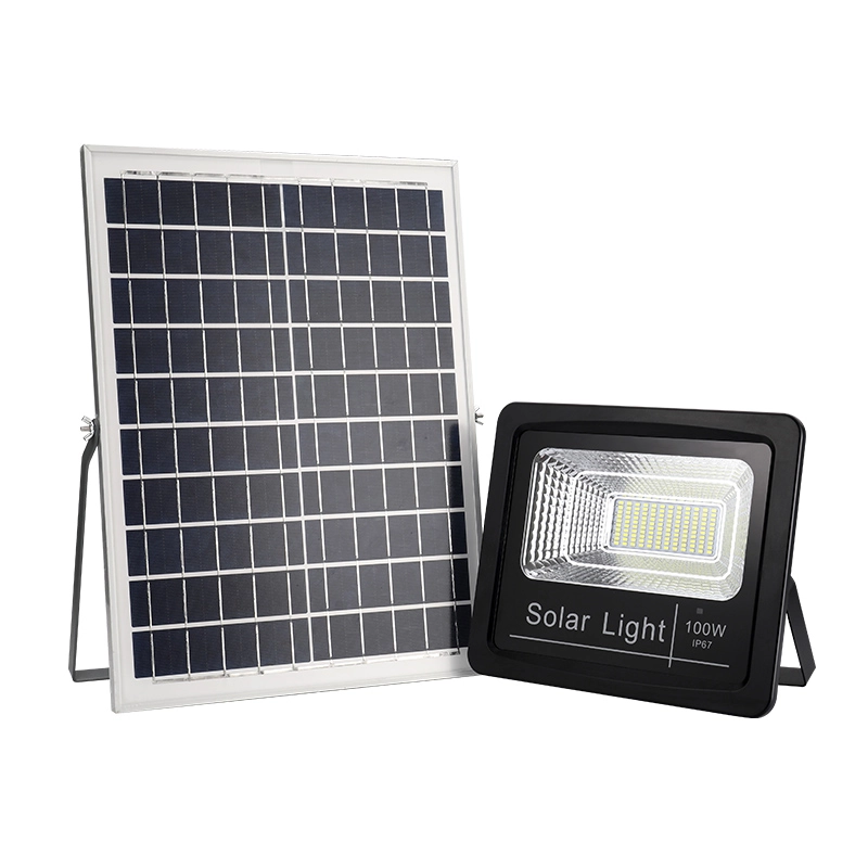
 Ms.Cici
 8618319014500