
Outdoor Spot Lights, Landscape Lighting - led spot lighting
To summarize, the IP-protected solution offers higher system density and lower cost compared to existing solutions. For a complete list of AC/DC and lighting controller offerings, please visit our LED Lighting & Illumination page or contact your local MPS sales office.
Furthermore, this solution can achieve less than 20mW of system standby power since the power section is highly integrated and more IC blocks can be left in the hibernating status at power off with an optimized, minimal operating frequency at no or light load.
Teardownmaps
While this topology seems ideal, this power stage faces two challenges: further minimizing the solution size and further decreasing standby power loss.
Technical Forum Questions answered by MPS engineers in 24h MP6951 and MP6908 sense method Dear MPSer, I would like to confirm the detection mechanisms of the MP6908 and MP6951: The MP6951 uses a voltage threshold (VP) generated based on th... AC-DC POWER CONVERTERS Latest activity 5 days ago 1 Comment How come there are no Synchronous LLC rectifiers that do not require a center tapped secondary? Hi, I checked all LLC synchronous rectifiers and none of them was for non-center tapped secondaries. Center tapped secondaries have poor transformer u... AC-DC POWER CONVERTERS Latest activity 2 weeks ago 2 Comments Does the MP6924 whether support the logic level of MOSFET? Hi Sir, I would like to know that MP6924 can support the logic level of SR MOSFETs? and in the LL mode have any side effect? thanks! AC-DC POWER CONVERTERS Latest activity a month ago 2 Comments Get technical support
Government initiatives regarding the installation of the smart lighting system, the popularity and affordability of wireless control, and growing awareness regarding the benefits of smart lighting systems are other key factors boosting the demand for smart lighting solutions globally. According to a 2017 study from Research and Markets, the global smart lighting market is projected to witness a compound annual growth rate of 25.44% to reach a total market size of US$21.2 billion by 2022 from US$6.8 billion in 2017 (2) .
Teardownbest maps
For LED current control, this solution implements a constant on-time (COT) control method, which also guarantees a high power factor. The on/off transition occurs during valley switching (by sensing through a zero-current detection (ZCD) pin) to eliminate turn-on loss and diode reverserecovery loss, which is also referred to as transition mode control. The IC also includes other features, such as minimum off time (to improve EMI), leading-edge blanking, over-voltage protection (OVP), over-current protection (OCP), over-temperature protection (OTP), and more.
Additionally, customers and legislation agencies are gradually noticing the importance of standby power consumption. Designers are expected to design smart lighting devices with super-low standby power to make the product attractive or sellable in certain regions with stringent energy consumption standards. For example, the European CoC Tier2 requires all external power supplies under the 49W power rating to have a standby loss of no more than 75mW. Smart lighting products are in the same way expected to meet certain energy specs in the near future (5). Currently, many smart light bulbs have high standby loss due to wireless circuitry power usage, which is inevitable, and therefore the standby loss can only be saved from the power stage.
If DIM senses the PWM signal from the MCU to control dimming, then the IC enters CC mode. The feedback voltage is modulated by reading DIM to modify the LED current based on the DIM duty cycle while keeping the CV output constant. As under CC mode, the MCU Vo pin must also be high enough, hence the IC is limited to a 5% minimal LED dimming depth to provide enough voltage to drive the MCU. The Vo power loop is decoupled from the main LED current loop by setting the ratio of current sense resistors (Rs1 and Rs2).
Teardown- Mod Pack
During CV mode (DIM pin is low), VCC acts as the supply to the IC. The ratio of N_flyback and Ns winding can be adjusted so the LED will not light up in CV mode. There is also a smart frequency modulation algorithm implemented to ensure low standby power and fast transient response to LED load changes, as well as ensuring there is no voltage drop at the MCU power, and no LED flickering during CV/CC transition.
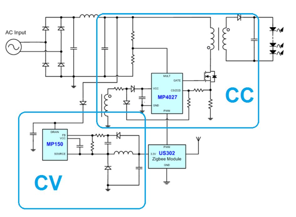
Referring to the teardown reports of some of commercially available smart light bulbs (such as Cree Connected Bulb (3) or Philips Hue (4)), the main structure of these bulbs are fairly similar (see Figure 1). A constant-current (CC) LED driver (such as the MPS MP4027) drives the main LEDs in addition to a constant-voltage (CV) buck driver (such as the MPS MP15x and MP17x) and provides either 5V or 3.3V to power the Zigbee/Wifi/Bluetooth/other transceiver IC and main microprocessor. The microprocessor in addition to the transceiver IC allows end users to control the lighting remotely using a mobile device. This control module sends a pulse-width modulation (PWM) or other digital signal (such as I 2C) to control the dimming of the LED driver.
TeardownNew York map
The operation mode of the MP4057A is summarized in Figure 4. During start-up, VDD is supplied by the N_Forward winding. Then the IC determines whether it should run in CV mode (to power the MCU only while the LED remains off) or CC mode (to power both the MCU and LED) by monitoring the DIM pin, which is controlled by the MCU itself.
By adopting the solution shown in figure 2, circuit designers can eliminate one control IC, one external inductor, and other resistors and capacitors, cutting PCB space and BOM cost by at least 20 - 30% in the power section of a smart light bulb (see Figure 3).
Smart lighting is considered to be the new frontier of the global lighting industry, as the trend of smart homes, Internet of Things (IoT), and a connected world are the main driving factors in global electronics growth. In terms of major applications of the smart lighting concept, the industry is currently more focused on light intensity dimming, lighting color temperature adjustment, ambient sensing, and monitoring. However, in the future, smart lighting applications can extend way beyond this range, the smart lighting devices can be used as a hub, integrated as key component of IoT systems and smart home/smart automation networks (1).
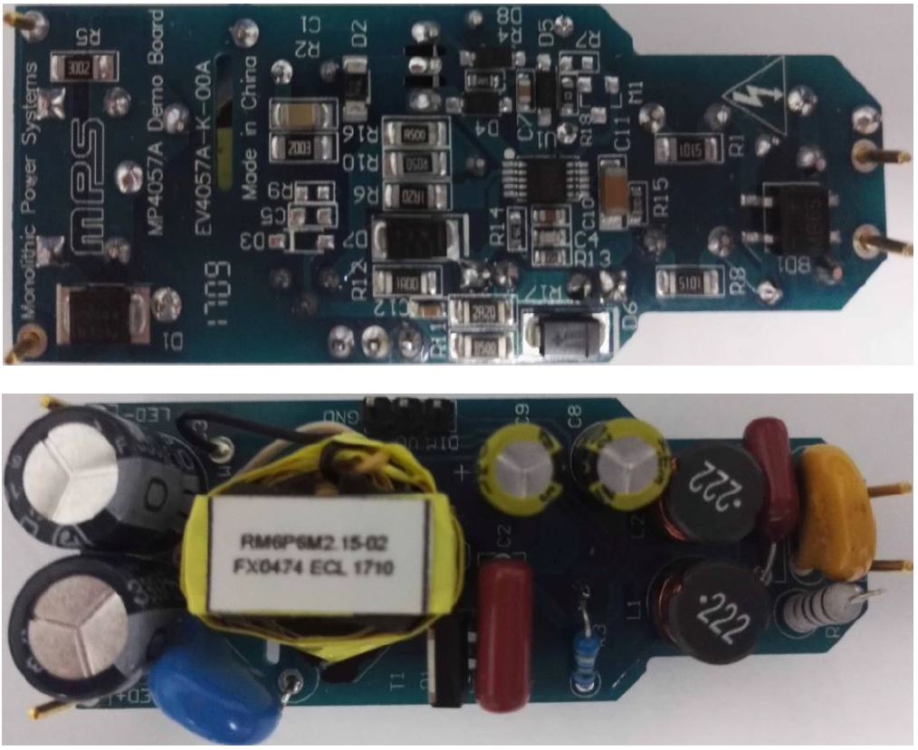
Figure 7: Evaluation Board EV4057A-K-00A:(L x W x H) 66mm x 25mm x 15mm230Vac/50Hz Input, Isolated Flyback Converter, VLED = 21V, ILED = 0.37A, Vo = 3.3V, Io = 50mA
Teardownmods
A19 and PAR bulb sizes follow industry standards and will not increase. Adding smart lighting functions to normal light bulbs means that the designer must squeeze more electronics into the same space, which is a big challenge, and the space limit may force designers to use fewer LEDs or use less LED power for easier thermal management. Sometimes, designers must adopt customized PCB shapes to fit all required electronics, which add to assembly cost.
To further shrink the size of smart lighting circuits and lower standby loss, a better integrated total power solution is presented in Figure 2. Here, the CV and CC circuits can be merged into a single-chip solution, shrinking the circuit BOM and standby loss.
Your email must be verified before you can log in. A message with a link to complete the verification process has been sent to your email address.
JavaScript seems to be disabled in your browser. For the best experience on our site, be sure to turn on Javascript in your browser.
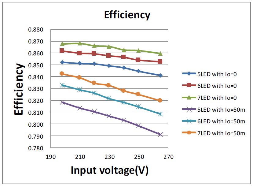
Figure 5 shows LED load efficiency and power factor performance, and Figure 6 shows a very linear PWM dimming performance. Figure 7 shows an 8W reference design circuit board suitable for all kinds of PAR lamps. For ordering information, MP4057A offers 3.3V for MCU power, while MP4057B offers 5V.


 Ms.Cici
 8618319014500