
Deconvolution of Brightfield images with Huygens - brightfield imaging
Official websites use .gov A .gov website belongs to an official government organization in the United States.
AllianceWS100
Articles from Proceedings of the National Academy of Sciences of the United States of America are provided here courtesy of National Academy of Sciences
This article contains supporting information online at https://www.pnas.org/lookup/suppl/doi:10.1073/pnas.2122937119/-/DCSupplemental.
Broadly, the reconstruction of an input object from the corresponding output image constitutes a well-known inverse problem in microscopy. Deconvolution, a standard method that addresses this problem, typically analyzes images in the Fourier domain and has been successfully applied to BF in 2D (8, 9). Here, we introduce optical sectioning in bright-field microscopy (OSBM), a 3D image reconstruction method based on analyzing in real space high-contrast BF images of phase objects.
AllianceAL500
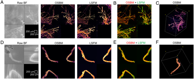
OSBM imaging for test samples and comparison with LSFM. (A–C) Fungal sample. (D–F) Clarified blood vessel sample. (A and D) Maximum intensity projection (MIP) images for BF, OSBM, and LSFM. (B and E) Merged images of OSBM (red) and LSFM (green) shown in A and D, respectively. (C and F) Three-dimensional images obtained from the corresponding OBSM optical sections. Field of view for C and F, 1,495 × 1,495 × 1,016 μm3 and 1,495 × 1,495 × 1,128 μm3, respectively.
This section collects any data citations, data availability statements, or supplementary materials included in this article.
AllianceBL200
An inverse-imaging problem is therefore identified, where BF image stacks featuring axial intensity gradients constitute the output signal. We reconstruct the input 3D object by finding the axial location of the source of these gradients, using standard digital processing filters (11). The set of points thus found corresponds to the scattering structures that compose the specimen.
AllianceBL300
To demonstrate 3D imaging using OSBM, we first consider a living filamentous network (T. atroviride), where scattering structures are well-localized and mostly distant from each other (compared to filament diameter). Application of OSBM results in a dramatic transition from blurred (original BF) to crisp (final) images (Fig. 2A). Excellent agreement is found between OSBM and LSFM (Fig. 2 A and B), enabling proper 3D rendering of hyphal structures (Fig. 2C and Movie S1). As OSBM does not use a narrowly focused laser beam, sharp images throughout the entire field of view are produced, thus complementing LSFM.
The classic bright-field (BF) microscope is an indispensable tool in any biological laboratory, routinely used to evaluate cellular or tissular morphology in stained two-dimensional (2D) samples. In the absence of staining, however, BF images of phase objects display little contrast (1). Several imaging modalities address this limitation, from early alternatives now widespread (e.g., Zernike phase contrast and differential interference contrast) (2) to recent advancements that allow quantitative measurement of the complex sample field (e.g., quantitative phase contrast) (3).
Image stacks and computer code used to analyze images have been deposited in Zenodo (https://zenodo.org/record/5931508#.YizNqzVMFPY). All other data are included in the manuscript and/or supporting information.
Altogether, OSBM excels at imaging sample boundaries of optically thin objects and structures with low axial spatial density. As a digital extension of traditional BF microscopy and complement to fluorescence microscopy techniques, OSBM offers a simple, direct, and model-free alternative for bioimaging in 3D.
Meningeal tissue was treated using CLARITY (14); optical microscopy and digital image processing were performed using a home-made setup (15) and Fiji (16), respectively.
AllianceGL300
One limitation for OSBM arises from contrast inversion of the pPSF. When two scattering structures are axially contiguous, they produce overlapped transition regions in the BF image, hindering proper object localization. This effect is expected to be marked for strongly scattering objects such as filaments (scattering intensity I ∝ r3, where r is radius of the filament) compared to point-like structures (I ∝ r6). In our experiments, we estimate that axial distances below 70 μm (40 μm) between scattering structures cause improper imaging for hyphal (meningeal tissue) samples.
The bright-field (BF) optical microscope is a traditional bioimaging tool that has been recently tested for depth discrimination during evaluation of specimen morphology; however, existing approaches require dedicated instrumentation or extensive computer modeling. We report a direct method for three-dimensional (3D) imaging in BF microscopy, applicable to label-free samples, where we use Köhler illumination in the coherent regime and conventional digital image processing filters to achieve optical sectioning. By visualizing fungal, animal tissue, and plant samples and comparing with light-sheet fluorescence microscopy imaging, we demonstrate the accuracy and applicability of the method, showing how the standard microscope is an effective 3D imaging device.
This work was supported by Consejo Nacional de Ciencia y Tecnología (Mexico) Grants IFC-2015-2/1144 and INFR-2018-295138 to B.G.-M. I thank Sergio Casas-Flores, Mitzuko Dautt, Miguel Condés-Lara, and Guadalupe Martínez-Lorenzana for gifts of samples; Ana Iris Peña-Maldonado for help with scanning electron microscopy; the Nanoscience and Nanotechnology Research National Laboratory (LINAN) at Instituto Potosino de Investigación Científica y Tecnológica for access to their facilities; and Isaac Carrillo-Acuña for assistance with fungal sample preparations.
AlliancePAL105
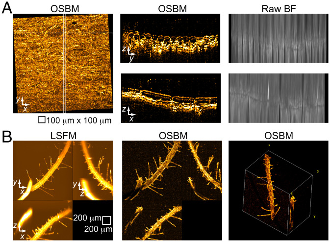
The OSBM procedure comprises operating a BF microscope under Köhler illumination (ς = 0.1 to 0.2), capturing a z-stack of images of unstained samples, and applying the following digital pipeline to images (Fig. 1D). First, large spatial structures are filtered out from raw BF images. Second, the z-gradient is computed by performing pairwise image subtraction, followed by Gaussian smoothing. Finally, a filter that highlights small, bright features (such as white top hat) is applied. Fig. 1D shows how OSBM works, applied to a living sample of the filamentous fungus Trichoderma atroviride. To validate OSBM, we compare resulting images with true optical sectioning (12) counterparts, using light-sheet fluorescence microscopy (LSFM). The background-free, axially localized spots produced by OSBM show good overlap with those from LSFM (Fig. 1E).
We applied OSBM to visualize untreated samples with different optical transmissivity. A layer of onion epidermal cells immersed in water is mostly transparent, enabling optimal visualization in BF. Accordingly, we observe the characteristic onion cell shapes in both longitudinal (x–z) and transversal (y–z) views (Fig. 3A), where periclinal wall curvature is readily identified. A comparison OSBM–LSFM for onion cells (Movie S3) shows good match and consistent cell wall imaging by OSBM in places where fluorescence is absent, emphasizing complementarity between OBSM and LSFM. As onion cell wall thickness is ∼6 μm (13), OSBM can detect isolated semiplanar scattering structures only a few micrometers thick (using a 10× objective lens). Finally, we consider seedlings of Arabidopsis thaliana, which present significant optical opacity. By comparing with LSFM, OSBM shows appropriate 3D imaging of thin root hairs and the surface of the thick root that faces the objective lens (Fig. 3B and Movie S4). For optically thick biological samples, using infrared light should help improve OSBM imaging (SI Appendix).
Author contributions: B.G.-M. designed research, performed research, contributed new reagents/analytic tools, analyzed data, wrote the paper, and received funds to perform research.
Next, we tested a sample with a continuous scattering structure, an optically cleared blood vessel (Fig. 2D). The OSBM image of this tissue is pointillistic, where the collective of points provides sharp localization of tissue boundary and structures such as pleats. A comparison between OSBM and LSFM images shows excellent correspondence in overall sample morphology (Fig. 2 D and E). A 3D reconstruction is shown in Fig. 2F and Movie S2.
Image stacks and computer code used to analyze images have been deposited in Zenodo (https://zenodo.org/record/5931508#.YizNqzVMFPY). All other data are included in the manuscript and/or supporting information.
Competing interest statement: B.G.-M. is inventor on USPTO patent application 17/550,797 submitted by Instituto Potosino de Investigación Científica y Tecnológica A.C. that covers “System and method for three-dimensional imaging of unstained samples using bright field microscopy.”
AllianceSL100
Principle of OSBM. (A) Schematic of our BF microscopy setup, showing illumination and scattered light rays (gray and green, respectively). Lenses are depicted as double arrows. (B) Image of the BF pPSF, computed using equation 1 in reference 9 with: λ = 450 nm, n = 1.0, NAobjective = 0.1; field of view (x–z): 90 × 404 μm2. (C) BF and scanning electron microscopy (SEM) images of a dry filamentous fungus sample (T. atroviride). BF image was acquired at z = −6.0 μm. (Scale bar: 100 μm.) (D) Digital pipeline of OSBM (round boxes) and resulting images for a living T. atroviride sample. (E) Overlay of the “final image” of OSBM shown in D (red) with the corresponding LSFM image (green).
This open access article is distributed under Creative Commons Attribution-NonCommercial-NoDerivatives License 4.0 (CC BY-NC-ND).
In BF with Köhler illumination (Fig. 1A), decreasing the numerical aperture (NA) of the condenser, establishing the coherent regime (NAcondenser/NAobjective = ς → 0) (2, 10), results in high-contrast imaging of phase specimens and strong contrast inversion upon axial scanning through focus. This behavior is evident in the phase point spread function (pPSF) (8, 9) (Fig. 1B); Weber contrast of the central spot changes from positive to negative and is zero at exact focus (z = 0). However, by introducing an amount of defocus close to the depth of field we find that BF imaging is in good correspondence with a ground truth (Fig. 1C and SI Appendix), suggesting accurate sample information can be extracted from BF.
Alliancelighting
Secure .gov websites use HTTPS A lock ( Lock Locked padlock icon ) or https:// means you've safely connected to the .gov website. Share sensitive information only on official, secure websites.
Despite drawbacks, BF remains attractive because it is a simple, fast, and inexpensive microscopy method, where photodamage and phototoxicity is much reduced compared to fluorescence microscopy. Three-dimensional (3D) imaging in BF has been obtained by processing multiple images acquired from different angles into a single reconstruction (4, 5) or using deep learning to predict 3D fluorescence signal (6, 7), although specialized instrumentation or extensive computer modeling is required.
Diameter: 6.25 in. (15.87 cm) Height: 2 in. (5.08 cm) Lens Height: 2.75 in. (6.98 cm) Lens Diameter: 1.5 in. (3.81 cm) Specifications and Features: Body: Brass area light hat, aged brass finish Lens: Polycarbonate frosted lens with rubber gaskets Warranty: Lifetime warranty
OSBM imaging of onion skin and plant root. (A) OSBM applied to a layer of onion epidermis, showing MIP images along x–y (Left), y–z, and x–z (Center). y–z and x–z images correspond to the white boxes shown in the x–y projection. BF maximum intensity projection images are shown (Right) for comparison. (B) Imaging of an unlabeled, untreated A. thaliana root sample. Field of view for 3D rendering, 1,495 × 1,495 × 1,008 μm3.


 Ms.Cici
 8618319014500