
3 Ways to Diffuse Light - how to diffuse light from led
Center Frequency (f0): The center frequency should be set to 915 MHz, as this is the frequency you want to pass through the filter.
All-passfilter
These are just a few examples of the frequency bands where bandpass filters are used in wireless applications. The choice of the appropriate frequency band and filter design depends on the specific requirements of the wireless system and the standards it needs to adhere to.
Radio receivers: Bandpass filters help select specific radio frequency bands for tuning to different stations or channels.
Medical devices: They are used in medical instruments like electrocardiograms (ECGs) and electroencephalograms (EEGs) to focus on specific physiological frequency components.
band passfilter中文
Signal processing: Bandpass filters can be employed in signal analysis to isolate specific frequency components of interest.
Bandwidth (BW): The bandwidth is the range of frequencies that the filter permits to pass through. It is usually specified as the difference between the upper and lower -3 dB cutoff frequencies (f1 and f2), where the signal power is reduced to half (-3 dB) of its maximum value. In other words, the bandwidth defines how wide the passband is.
Component Selection: Choose appropriate passive components (inductors, capacitors, and sometimes resistors) and active components (if using an active filter) with values that meet your design specifications.
Bandpass filters are essential tools in wireless applications because the selective filtering of specific frequency ranges is required or at least, very advantageous.
Bandwidth (BW): The bandwidth of the filter will depend on your specific application. For ISM applications like LoRa, Sigfox, or other narrowband systems, the bandwidth may be relatively narrow, such as a few MHz or even less. For Wi-Fi or other broadband applications, the bandwidth may be wider, up to several hundred MHz.
Highpass filter
In the context of wireless RF (Radio Frequency) applications, the term "bandpass filters" is more commonly used than "band pass filters."
Our support in high-throughput microscopy also includes RNAi technology, assay development, pilot screen validation and automated image acquisition
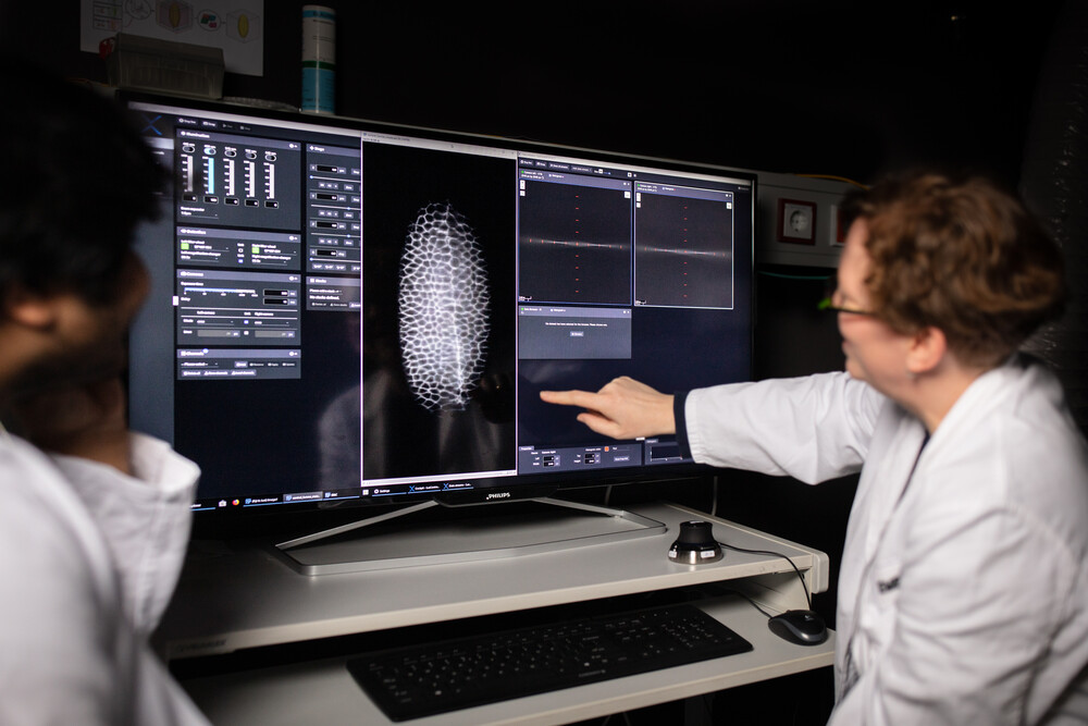
The ALMF supports in-house scientists and visitors in using light microscopy methods for their research. We are assisting throughout the process of microscopic imaging: planning of a project, sample preparation, selection and usage of the microscope, image processing and visualisation, data transfer and storage.
The Advanced Light Microscopy Facility (ALMF) offers a collection of state-of-the-art light microscopy equipment and image processing tools.
Bandpass filters are commonly used in various wireless applications to select specific frequency bands of interest while attenuating unwanted frequencies. The choice of frequency bands for bandpass filters in wireless applications depends on the particular wireless communication standard or technology being used. Here are some common frequency bands and their associated wireless applications:
Center Frequency (f0): This is the midpoint or central frequency within the desired passband. It defines the frequency around which the filter allows maximum signal transmission.
Center Frequency (f0): This is the midpoint or central frequency within the desired passband. It defines the frequency around which the filter allows maximum signal transmission.
Bandpassfiltertransfer function
Bandpass filters are essential tools in wireless applications because the selective filtering of specific frequency ranges is required or at least, very advantageous.
Bandpass filters can come in various designs, including active filters (using active components like operational amplifiers) and passive filters (using passive components like capacitors and inductors). They can be implemented as analog circuits or digital algorithms in signal processing.
These are just a few examples of the frequency bands where bandpass filters are used in wireless applications. The choice of the appropriate frequency band and filter design depends on the specific requirements of the wireless system and the standards it needs to adhere to.
A band pass filter is a device for wireless signal processing that is designed to allow a specific range of frequencies to pass through while attenuating or blocking frequencies outside of that range. It effectively filters out unwanted frequencies and only permits signals within a specified frequency band to be transmitted or received.
Bandpassfiltercircuit
If you would like to apply as a visitor in the ALMF, please contact us by email including a short overview of your project. We will discuss the feasibility of your project internally and in case of a positive evaluation we will contact you for a more detailed meeting over the phone, via Skype or video conference.
Topology: Select the appropriate filter topology based on your requirements and the available components. Common topologies for RF filters include LC (inductor-capacitor), SAW (Surface Acoustic Wave), and ceramic filter.
Bandpass filters are commonly used in various wireless applications to select specific frequency bands of interest while attenuating unwanted frequencies. The choice of frequency bands for bandpass filters in wireless applications depends on the particular wireless communication standard or technology being used. Here are some common frequency bands and their associated wireless applications:
Communication systems: Bandpass filters are used in modulators and demodulators to extract the carrier signal from a modulated waveform.
In the context of wireless RF (Radio Frequency) applications, the term "bandpass filters" is more commonly used than "band pass filters."
It's important to note that designing RF filters can be complex, and it often requires simulation tools and expertise in RF engineering. Depending on your specific needs, you may choose to design a custom filter or purchase a commercially available bandpass filter that meets your frequency and bandwidth requirements at 915 MHz. Commercial filters are often available with datasheets that provide detailed specifications, making them a convenient choice for many applications.
Radio receivers: Bandpass filters help select specific radio frequency bands for tuning to different stations or channels.
EMBL is Europe’s life sciences laboratory – an intergovernmental organisation with more than 80 independent research groups covering the spectrum of molecular biology.
Butterworthfilter
If you need bandpass filters for a frequency other than those that we offer on this page, please let us know and we will add them to our product offerings.
Filter Type: There are various filter designs to choose from, such as Butterworth, Chebyshev, or elliptic filters. The choice depends on your specific requirements for filter characteristics like passband ripple, stopband attenuation, and steepness of rolloff.
Impedance Matching: Ensure that the filter is impedance-matched to the input and output of your system to minimize signal reflection and maximize signal transfer.
Impedance Matching: Ensure that the filter is impedance-matched to the input and output of your system to minimize signal reflection and maximize signal transfer.
Band pass filter
Bandwidth (BW): The bandwidth of the filter will depend on your specific application. For ISM applications like LoRa, Sigfox, or other narrowband systems, the bandwidth may be relatively narrow, such as a few MHz or even less. For Wi-Fi or other broadband applications, the bandwidth may be wider, up to several hundred MHz.
Medical devices: They are used in medical instruments like electrocardiograms (ECGs) and electroencephalograms (EEGs) to focus on specific physiological frequency components.
We are happy to welcome visitors in the Advanced Light Microscopy Facility if capacity allows.Please note that visitors from EMBL’s Member or Associated Member States are our first priority.
Communication systems: Bandpass filters are used in modulators and demodulators to extract the carrier signal from a modulated waveform.
Filter Type: There are various filter designs to choose from, such as Butterworth, Chebyshev, or elliptic filters. The choice depends on your specific requirements for filter characteristics like passband ripple, stopband attenuation, and steepness of rolloff.
Filter Order: The filter order determines how steeply the filter attenuates frequencies outside the passband. Higher-order filters provide better selectivity but may have a more complex design and require more components.
Lowpass filter
A band pass filter is a device for wireless signal processing that is designed to allow a specific range of frequencies to pass through while attenuating or blocking frequencies outside of that range. It effectively filters out unwanted frequencies and only permits signals within a specified frequency band to be transmitted or received.
Signal processing: Bandpass filters can be employed in signal analysis to isolate specific frequency components of interest.
It's important to note that designing RF filters can be complex, and it often requires simulation tools and expertise in RF engineering. Depending on your specific needs, you may choose to design a custom filter or purchase a commercially available bandpass filter that meets your frequency and bandwidth requirements at 915 MHz. Commercial filters are often available with datasheets that provide detailed specifications, making them a convenient choice for many applications.
If you need bandpass filters for a frequency other than those that we offer on this page, please let us know and we will add them to our product offerings.
Topology: Select the appropriate filter topology based on your requirements and the available components. Common topologies for RF filters include LC (inductor-capacitor), SAW (Surface Acoustic Wave), and ceramic filter.
Filter Order: The filter order determines how steeply the filter attenuates frequencies outside the passband. Higher-order filters provide better selectivity but may have a more complex design and require more components.
Component Selection: Choose appropriate passive components (inductors, capacitors, and sometimes resistors) and active components (if using an active filter) with values that meet your design specifications.
Center Frequency (f0): The center frequency should be set to 915 MHz, as this is the frequency you want to pass through the filter.
Bandwidth (BW): The bandwidth is the range of frequencies that the filter permits to pass through. It is usually specified as the difference between the upper and lower -3 dB cutoff frequencies (f1 and f2), where the signal power is reduced to half (-3 dB) of its maximum value. In other words, the bandwidth defines how wide the passband is.
Bandpass filters can come in various designs, including active filters (using active components like operational amplifiers) and passive filters (using passive components like capacitors and inductors). They can be implemented as analog circuits or digital algorithms in signal processing.


 Ms.Cici
 8618319014500