
Industrial LED Lighting | Emerson US - e led lighting
The horizontal rows of five points (i.e.A1, B1,C1, D1 andE1) are connected to each other. There is a middle channel (sometimes called the trough) that separates the two sides (i.e. A1,B1, C1,D1 and E1 are NOT connected to F1,G1, H1,I1 and J1).
Take a look at the code and see if you understand what each line does. Try modifying a couple of elements and then reuploading to see how the LED responds. Can you make it blink faster?
How to identify positive and negative terminal ofLED
We welcome the opportunity to serve you with your specific requirements. You will hear from us quickly and with the best price possible.
SMDLEDpolarity marking on PCB
Remember that LEDs have polarity, so pay special attention to which terminal goes where! You want the longer pin + to be closer to the 5V power, and the shorter pin - to be closer to ground.
LEDplus minus
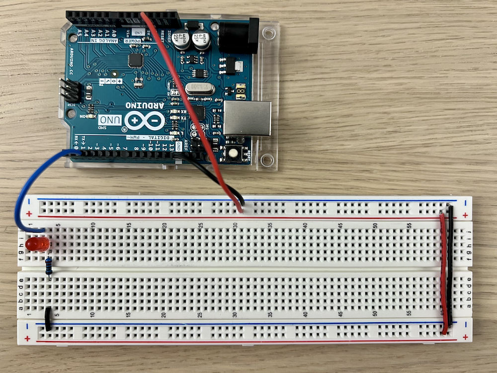
Next, we can connect the Arduino Uno to bring in power to our breadboard. Staying with convention, we will connect the red power rail to the arduino's 5V power supply and the black or blue power rail to the arduino's 0V ground.
Now, copy and paste the code below into your Arduino IDE and hit upload! If you've done everything successfully, you should see your LED blinking! Hooray!
Polarizers are optical filters widely used for hot spots or glare reductions, stress evaluations and contrast enhancement in imaging applications. It can also perform different measurements in acoustic vibrations, molecular structures, change in magnetic fields, chemical interactions and temperature. The light transmission that passes through a polarizer depends strongly on the direction of the polarization.
The "Diode" part of LED means that it's a component that only allows current to flow in one direction. As such, LEDs have what's called apolarity: there is a positive + side and a negative - side. Like how the battery terminals were labeled in the circuit diagram in Chapter 2.
LEDsymbol
Here at Lambda Research Optics, we offer a wide range of polarization optics that include calcite, plate, cube, to waveplates polarizers. Our polarizer lineup has been continually expanding to cater to the requirements of our customers. If you can’t find what you are looking for, please contact one of our engineers using our contact form or call us. We’ll be ready to assist you.
Polarized light can have circular, elliptical or linear polarization. In choosing the best polarizer for your application, consider its extinction ratio, transmission, acceptance angle, construction, clear aperture, optical path length, damage threshold and costing.
If you're getting errors in the Arduino IDE, try to read through the error messages. They're more helpful than people often give them credit for. There may be a lot of jargon, but usually a line or two will be in human-readable language that will help you resolve the issue!
LEDpositive negative symbol
Review the steps carefully, making sure you've wired up everything as intended. Even a single connection being broken may cause your circuit to not work!
LEDanode cathode diagram
In this chapter, we're going to put together a simple circuit that demonstrates a small sliver of the Arduino Uno's capabilities. Our circuit will consist of the humble Arduino Uno microprocessor, some wires, a resistor, and a LED (a small but metaphorically powerful light source). Being able to control this LED programmatically is the next step to build your own version of the MIT Illuminations lights at home!
LEDsymbol circuit
LEDs have a couple indicators of their polarity. The convention is to have the longer terminal (also called a pin or a lead) and round side be positive +, and the shorter terminal and flat side be negative -. Oftentimes, if you wire it the wrong way around, the LED will not light up when you expect it to.
We won't be using both sides of these power rails for this exercise, but it's always a good idea to have them wired up together. It'll save you some prep-work later if or when you do decide to use both sides!
In the image below, we're showing three examples of points that are connected to each other - two horizontal rows and one power rail. Note that each purple outline indicates one group of points.
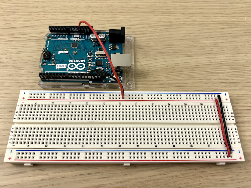
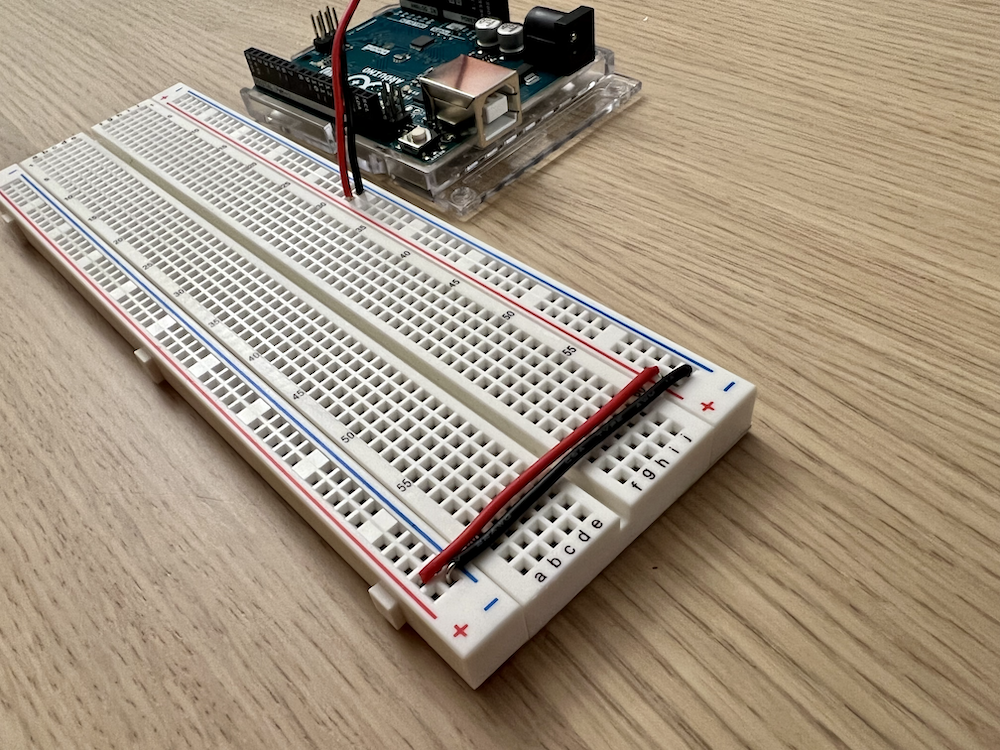
Our first step is to connect both power rails on the breadboard to each other, and then to a power source. When everything is set up, we call them the power bus lines or buses for short.
LEDpolarity marking on PCB
Before there's any electricity involved, we want to connect the power rails on both sides of the breadboard. It's good practice to use red wire for the red power rail (which will be connected to the 5V power supply) and black wire for the blue power rail (which will be connected to ground) - if those colors are available.
Now that our breadboard has power, we'll add an LED (along with a resistor and a couple more wires). We've provided suggestions of which points to insert wires or the component pins. But as long as you make sure to use connected points on the breadboard, you should be good to go.
The final step is to upload code to the Arduino Uno that will tell the LED to blink! This is a step that sometimes can be a bit tricky (connection errors, etc.) so take your time with it and believe in yourself!
We've got a lot of components we want to assemble together; how do we actually connect them? Introducing: breadboards! A breadboard is a tool that allows you to easily wire up a circuit by sticking the contacts of components directly into the holes, which we'll call points.
The two-hole-wide columns next to both of the long edges of the breadboard are your power rails. Typically, the one next to the red line is connected to your power source (in this case, 5V) and the one next to the black or blue line is connected to your ground (in this case, 0V). The power rails on opposite sides of the breadboard are NOT connected to one another.
The light emitting diode, or LED, is a component that emits light when an electric current is passed through it, much like a light bulb! However, unlike light bulbs, LEDs are much more efficient (much less of the energy that powers them is converted into heat) and can be used to create a variety of different colors.


 Ms.Cici
 8618319014500