
Hull wake measurement in steady drift using a boroscopic ... - boroscopic
A metallurgical microscope is a special version of a standard light microscope for the study of materials, such as Metals, plastics, ceramics and others. Since materials are usually not transparent solid structures, metallurgical microscopes often have an upright light unit. Moreover, this type of microscope is characterized by extensive magnification, e.g. for detailed investigations of surface structures. Application areas of metallurgical microscopy are industry, material science and research.
M125 pin connectorpinout
pico+15/WK/I | ultrasonic sensor | current output 4-20 mA ✓ M18 housing ✓ variant with 90° angled head ✓ Made in Germany ✓ personal support ✓ pico+15/WK/I
M12D codepinout

The wiring diagram is shown in the 4th image. You need a 10-30v supply. Use a 250 ohm load resistor and measure the voltage across it.
M124pinout
JavaScript seems to be disabled in your browser. For the best experience on our site, be sure to turn on Javascript in your browser.
overview | cabel | plug connections and cables for individual connection solutions | accessories for microsonic ultrasonic sensors | overview | cabel
The mfg specifies it as a "5-pin M12 initiator plug". I'll venture a guess that you will not find a "cable" to use this with an Arduino.
M124 pin Connector Color Code
KST5G-2/M12 | plug connections and cables for individual connection solutions | accessories for microsonic ultrasonic sensors | KST5G-2/M12
M12 a coded pinoutvsm12
Phase contrast microscopy is a contrast-enhancing technique to visualize structures difficult to detect with bright-field microscopy due to a lack of contrast, without the need of a staining. When penetrating a medium, light propagates with different speeds depending on the refractive index of the medium. This leads to phase differences, which are converted to differences in brightness by the microscope using phase rings. Areas of application of phase contrast microscopes are mainly the observation of living biological samples in order to resolve fine structures with high contrast.
M12 a coded pinoutadapter
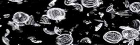
A dark field microscope produces a contrast-enhanced image by indirect illumination of the specimen, thereby also unstained specimens can be displayed with high contrast. Using this technique, direct light is bypassing the objective, only light scattered by the specimen enters the objective. As a result, the background appears dark or black, only the specimen is illuminated and even small structures can be visualized with high contrast. Dark field microscopy in biology and medicine is especially used for transparent and low contrast specimens, for example, studying blood, small animals or micro-particles in material science.
Polarization microscopy is used for the analysis of optically anisotropic samples. The primary objective of polarization microscopy is not magnification of an object, but rather the analysis of optical properties such as refractive index or birefringence for sample analysis. The method is mainly used in mineralogy and in industry for testing plastics or mineral building materials in order to gain insights into their composition.
Standard bright-field microscopes are used for daily laboratory routine in research and diagnostics for simple, standard applications that require no special equipment. Therefore simple optical systems and lenses are applied.
I see, but then how would I be able to code the sensor and have it used with the arduino? I have only ever used the HC-SR04 ultrasonic sensor and that requires two pins, one for echo and one for trig, so how would I be able to use this one.
M12connector wiring diagram
I am using the pico+15/WK/I ultra sonic sensor for this project I am working on. Essentially I want to know distance using this very tiny sensor however the connector on the sensor is a 5 pin M12 connector. The arduino has no apparent plug that I can see (however I am often wrong). Please help.
I have tried looking for some sort of adapter that would allow me to use both the sensor and arduino but I am stuck. Does anyone know whether this is possible or am I out of luck.
Which Arduino? What supply voltage will you be using for the sensor (10 ~ 30)? You may need a voltage divider to lower the output voltage to suit your Arduino, you cannot apply more than Vcc + 0.5 volts to an Arduino pin.
An inverted microscope is an upside-down standard light microscope. This type of microscope is characterized by locating the objective underneath the stage and pointing upwards to the specimen. Inverted microscopes are mainly used for live cell analysis of cell cultures growing in culture medium. Culture dishes are not only available with standard coverslip bottoms (thickness 0.17mm) but also in various material and bottom thicknesses. Therefore, for some models special objectives are available that can correct for different bottom glass thicknesses. In addition, inverse microscopes are also used for studies of thicker specimens. Inverted microscopes are also available as dark field, polarization or fluorescence microscopes.
M12 a coded pinoutwiring diagram
JohnRob: The mfg specifies it as a "5-pin M12 initiator plug". I'll venture a guess that you will not find a "cable" to use this with an Arduino.
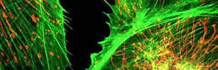
The physical principle of fluorescence is used to selectively visualize and localize defined fluorescent structures, while non-fluorescent structures remain dark in order to obtain a high image contrast. For this purpose, fluorescent dyes (fluorochromes) are used with specific excitation and emission filters installed in the optical path of the microscope. A wide range of fluorescent dyes with different colors are available, which are used in molecular biological, biomedical and clinical research. For example, in immunohistochemistry, fluorescence-in-situ-hybridization and for visualization of cells or cellular components in living/fixed specimens.


 Ms.Cici
 8618319014500